
Hydronic heating is the use of hot water to distribute heat. Hydronic heating is discussed in this compliance 'manual as an “alternative system” because it is much less common in California than in other parts of the United States.
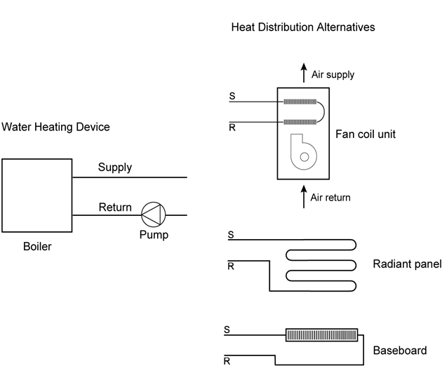
A hydronic heating system consists of a heat source, which is either a boiler or water heater, and a distribution system. There are three main types of hydronic distribution systems, and they may be used individually or in combination: baseboard convectors or radiators, hot water air handlers, and radiant panel heating systems. These three options are illustrated in Figure 4-32.
Baseboard convectors or radiators are most effective when mounted near the floor. Cool air drawn by gravity over heated panels or finned tubes is heated and pushed upward to warm the room. These devices also increase the mean radiant temperature of the space, improving comfort. Baseboard convectors or radiators do not require ducting.
Air handlers consist of a blower and finned tube coil enclosed in a sheet metal box (similar to a typical residential furnace) and may be ducted or nonducted. Air handlers may also include refrigerant coils for air conditioning. Some air handlers are compact and can fit under cabinets.
Radiant panels may be mounted on or integrated with floors, walls, and ceilings. Radiant floor panels are most typical. See the separate section below for additional requirements specific to radiant floor designs.
For hydronic heating systems without ducts, the mandatory measures cover only pipe insulation, tank insulation, and boiler efficiency. Otherwise, for fan coils with ducted air distribution, the mandatory air distribution measures also apply. For combined hydronic systems, as described below, mandatory water heating requirements also apply to the water heating portion of the system.
A. Pipe and Tank Insulation
§150.0(j) Water System Pipe and Tank Insulation and Cooling Systems Line Insulation, §120.3 Requirements for Pipe Insulation
The typical residential hydronic heating system operating between 105° and 140° F must have at least 1 inch (25 mm) of insulation on pipes less than 1 inch in diameter and 1.5 inch (38 mm) of insulation on pipes between 1 inch and less than 1.5 inches in diameter. Systems operating between 141° and 200° F must have at least 1.5 inches of insulation on pipes less than 1.5 inches in diameter. For other temperatures and pipe insulation characteristics, see Table 4-5.
There are a few exceptions where insulation is not required:
1. Sections of pipes where they penetrate framing members.
2. Pipes that provide the heat exchange surface for radiant floor heating.
3. Piping in the attic that is covered by at least 4 inches (100 mm) of blown insulation on top.
4. Piping installed within walls if all the requirements for Insulation Installation Quality are met (see Chapter 3 Building Envelope Requirements).
If the system includes an unfired hot water storage tank, then the tank must be either wrapped with R-12 insulation or insulated internally to at least R-16.
Source: Richard Heath & Associates/Pacific Gas & Electric
Source: Richard Heath & Associates/Pacific Gas & Electric
For pipes in hydronic heating systems that operate at pressure greater than 15 psi, the requirements of §120.3 apply. These are the same requirements that apply to nonresidential piping systems.
B. Boiler Efficiency
Gas or oil boilers of the size typically used for residential space heating (less than 300,000 Btu/h capacity) must be rated with an AFUE of 80 percent or greater (See Appliance Efficiency Regulations, Title 20 for minimum efficiencies of other heating equipment). A gas or oil water heater may also be used as a dedicated source for space heating. Other hot water sources, including heat pumps or electric resistance water heaters, are not allowed for use in dedicated space heating systems. Therefore, some water heaters may be used for space heating only if used as part of a combined hydronic system as described below. In that case, the mandatory water heater requirements apply.
Thermostat requirements also apply to hydronic systems as described in Section 4.5.1.
There are no specific prescriptive requirements that apply to hydronic systems. However, if the system has a fan coil with ducted air distribution, the relevant prescriptive requirements apply, including duct insulation and duct sealing.
Credit for choosing a hydronic heating system is possible using the performance compliance method. The standard design is assumed to have a furnace and ducted air distribution system. Therefore, hydronic systems without ducts can take credit for avoiding duct leakage penalties. In 'addition, minimizing the amount of pipe outside conditioned space will provide some savings. Hydronic heating compliance calculations are described in the Residential ACM 'Manual.
If the proposed hydronic system includes ducted air distribution, then the associated compliance options described earlier in this chapter may apply, such as adequate airflow (if there is air conditioning) and supply duct location.
A “combined hydronic” system is another compliance option that is possible when using the performance method. Combined hydronic heating refers to the use of a single water heating device as the heat source for both space and domestic hot water heating.
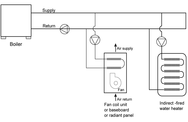
There are two types of combined hydronic systems. One uses a boiler as a heat source for the hydronic space heating system. The boiler also heats domestic water by circulating hot water through a heat exchanger in an indirect-fired water heater.
Source: Richard Heath & Associates/Pacific Gas & Electric
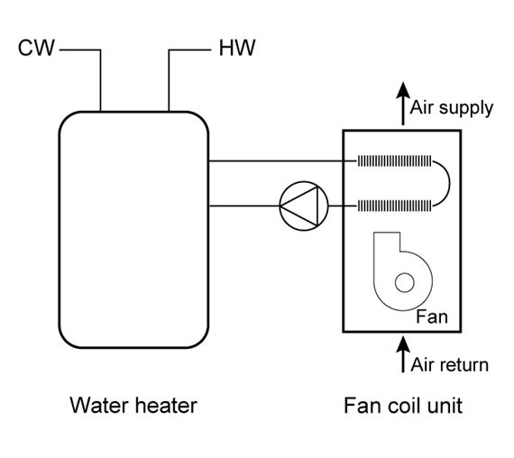
The other type of hydronic heating uses a water heater as a heat source. The water heater provides domestic hot water as usual. Space heating is accomplished by circulating water from the water heater through the space heating delivery system. Sometimes a heat exchanger is used to isolate potable water from the water circulated through the delivery system. Some water heaters have built-in heat exchangers for this purpose.
For compliance calculations, the water heating function of a combined hydronic system is analyzed for water-heating performance as if the space heating function were separate. For the space-heating function, an “effective” AFUE or HSPF rating is calculated. These calculations are performed automatically by the compliance software.
One type of distribution system is the radiant floor system, either hydronic or electric, which must meet mandatory insulation measures (See below). Radiant floors may take one of several forms. Tubing or electric elements for radiant floor systems may be:
•Embedded in a concrete floor slab.
•Installed over the top of a wood subfloor and covered with a concrete topping.
•Installed over the top of wood subfloor in between wood furring strips.
•Installed on the underside surface of wood subfloor.
In the latter two types of installations, aluminum fins are typically installed to spread the heat evenly over the floor surface, and to reduce the temperature of the water as required. All hydronic systems use one or more pumps to circulate hot water. Pumps are controlled directly or indirectly by thermostats, or by special outdoor reset controls.
|
Location of Insulation |
Orientation of Insulation |
Installation Criteria |
Climate Zone |
Insulation |
|
Outside edge of heated slab, either inside or outside the foundation wall
|
Vertical
|
From the level of the top of the slab, down 16 inches or to the frost line, whichever is greater? Insulation may stop at the top of the footing where this is less than the required depth. For below-grade slabs, vertical insulation shall be extended from the top of the foundation wall to the bottom of the foundation (or the top of the footing) or frost line, whichever is greater. |
1-15 |
5 |
|
16 |
10 | |||
|
1-15 |
5 | |||
|
Between heated slab and outside foundation wall |
Vertical and Horizontal |
Vertical insulation from the top of the slab at the inside edge of the outside wall down to the top of the horizontal insulation. Horizontal insulation from the outside edge of the vertical insulation extending 4 feet toward the center of the slab in a direction normal to the outside of the building in the plan view. |
16 |
10 vertical and |
Source: 2016 Energy Standards Table 110.8-A
Radiant floor systems in concrete slabs must have insulation between the heated portion of the slab and the outdoors.
When space heating hot water pipes or heating elements are set into a concrete slab-on-grade floor, slab-edge insulation from the level of the top of the slab, down 16 inches (200 mm) or to the frost line, whichever is greater (insulation may stop at the top of the footing, where this is less than the required depth)is required. Alternatively, insulation may be installed down from the top of the slab and wrapped under the slab for a minimum of 4 ft toward the middle of the slab. The required insulation value for each of these insulating methods is either R-5 or R-10 depending on climate zone as shown in Table 4-18. Any part of the slab extending outward horizontally must be insulated to the level specified in Table 4–18.
When using the performance compliance method with slab-on-grade construction, the standard design includes slab edge insulation as described above using the F-factors in Reference Joint Appendix JA4, Table 4.4.8.
When space-heating hot water pipes or heating elements are set into a lightweight concrete topping slab laid over a raised floor, insulation must be applied to the exterior of any slab surface from the top of the slab where it meets the exterior wall, to the distance below ground level as described in Table 4–18. If the slab does not meet the ground on the bottom surface, the specified insulation level must be installed on the entire bottom surface of the raised slab. Any part of the slab extending outward horizontally must be insulated to the level specified in Table 4–18. For lightweight slabs installed on raised floors and inside exterior walls, the overall wall R-value and overall floor R-value (determined as 1/(U-factor)) may be counted toward meeting the minimum R-value requirements specified in Table 4–18.
Raised floor insulation that meets the mandatory minimum R-value for wood floor assemblies also meets the requirement for insulation wrapping under the lightweight topping slab.
Slab edge insulation applied to basement or retaining walls (with heated slab below grade) must be installed so that insulation starts at or above ground level and extends down to the bottom of the foundation or to the frost line, whichever is greater.

Source: California Energy Commission
Local conditions (such as a high water table) may require special insulation treatment to achieve satisfactory system performance and efficiency. To determine the need for additional insulation, follow the recommendations of the manufacturer of the hydronic tubing or heating element being installed. Where there is a danger of termite infestation, install termite barriers, as required, to prevent hidden access for insects from the ground to the building framing.
In 'addition to the insulation R-value requirements, §110.8(g)1 also sets mandatory measures related to moisture absorption properties of the insulation and protection of the insulation from physical damage or pest intrusion.
Example 4-40
Question:
My client wants a dedicated hydronic-heating system (space
heating only), but a few things are unclear: (1) What piping insulation is
required? (2) Can I use any compliance approach? (3) Do I have to insulate the
slab with slab edge insulation? (4) What special documentation must be submitted
for this system type?
Answer:
(1) The supply
lines not installed within a concrete radiant floor must be insulated in
accordance with §150.0(j)2—
Systems operating between 105° and 140° F must have at least 1 inch of
insulation on pipes less than 1 inch in diameter, and 1.5 inches of insulation
on pipes between 1 inch and less than 1.5 inches in diameter. Systems operating
between 141° and 200° F must have at least 1.5 inches of insulation on pipes
less than 1.5 inches in diameter.
(2) You can use any compliance approach, but the boiler must meet the mandatory efficiency 80 percent AFUE.
(3) The slab edge insulation shown in Table 4–18 is required only when the distribution system is a radiant floor system (pipes in the slab). When this is the case the insulation values shown are mandatory measures (no modeling or credit).
(4) No special documentation is required.
Example 4-41
Question:
What are the slab edge insulation requirements for a hydronic-heating system with the hot water pipes in the slab?
Answer:
The requirements for slab edge insulation can be found in §110.8 and §150.0(l).
Material and installation specifications are as follows:
1. Insulation values as shown in Table 4–18
2. Protected from physical damage and ultra-violet light deterioration
3. Water absorption rate no greater than 0.3 percent (ASTM-C272)
4. Water vapor permeance no greater than 2.0 per inch (ASTM-E96-14).
Evaporative coolers cool a building by either passing outdoor air through a wetted evaporative medium (direct evaporative cooler), by indirect cooling through a nonporous heat exchanger separating evaporatively cooled secondary air from outdoor air, or by a combination indirect-direct system that combines an indirect heat exchanger with a downstream direct evaporative process. Although direct coolers are the most common systems available, the more advanced indirect and indirect-direct systems offer generally lower supply air temperatures with less moisture 'addition introduced to the indoor space. For the Energy Standards, performance credit is allowed only for indirect and indirect-direct evaporative cooling systems. All coolers receiving credits within the ACM 'Manual must be 'listed in the Energy Commission’s Title 20 Evaporative Cooler appliance database.
Evaporative coolers may be used with any compliance approach. In the prescriptive compliance approach, all evaporative coolers are treated as a minimum efficiency 13.0 SEER air conditioner.
In the performance approach the compliance software uses an hourly model based on unit effectiveness, supply airflow, and power to determine the magnitude of the credit based on climate conditions and unit sizing relative to the loads. Typical cooling budget credits are 20-30 percent, depending upon these factors.
The evaporative cooling system must meet the following requirements to receive credit based on the hourly performance method described above. Direct coolers, as well as indirect and indirect-direct coolers not meeting these criteria shall be modeled as a minimum efficiency (13.0 SEER) central air conditioner.
1. The equipment manufacturer shall certify to the Energy Commission that water use does not exceed 7.5 gallons per ton hour based on the Title 20 Appliance Efficiency Regulations testing criteria.
2. Equipment shall be permanently installed (no window or portable units).
3. Installation shall provide for automatic relief of supply air from the house with maximum air velocity through the relief dampers not exceeding 800 fpm (at the Title 20 rated airflow). Pressure relief dampers and ductwork shall be distributed to provide adequate airflow through all habitable rooms. For installations with an attic, ceiling dampers shall be installed to relieve air into the attic and then outside through attic vents. For installations without an attic, sidewall relief dampers are acceptable.
4. To minimize water consumption, bleed systems are not allowed.
5. A water quality management system (either “pump down” or conductivity sensor) is required. “Pump down” systems can either be integral to the evaporative cooler or they can be accessories that operate on a timed interval. The time interval between pumps shall be set to a minimum of 6 hours of cooler operation. Longer intervals are encouraged if local water quality allows. Automatic systems that use conductivity sensors provide the best water efficiency compared to a timed pump down system. These sensors monitor the water quality and don’t unnecessarily drain the water based on elapsed time.
6. Automatic thermostats are required. Manual on/off controls are not allowed.
7. If the evaporative cooler duct system is shared with a heating and/or cooling system, the installed duct system shall employ backdraft dampers at the evaporative cooler supply.
8. The installing contractor must provide a winter closure device that substantially blocks outdoor air from entering the indoor space.
9. The size of the water inlet connection at the evaporative cooler shall not exceed 3/8 inch.
10. Unless prohibited by local code, the sump overflow line shall not be directly connected to a drain and shall terminate in a location that is normally visible to the building occupants.
Example 4-42
Question:
How are applications with vapor compression cooling systems and evaporative cooling systems handled?
Answer:
In situations where both evaporative cooling system(s) and vapor compression system(s) are installed in a house, the size of the evaporative cooler will dictate the magnitude of the credit. The performance approach will ensure that an evaporative cooler sized to meet most of the cooling loads will generate a higher credit than one sized to meet a fraction of the design cooling load.
Example 4-43
Question:
How do you model multiple evaporative coolers on one house?
Answer:
In situations with multiple evaporative coolers, effectiveness inputs should be averaged, and airflow and power inputs should be totaled. Performance characteristics of each piece of equipment should be 'listed on the compliance forms.
|
Appliance |
Rating Condition |
Minimum Standard |
|
Ground water source heat pumps (cooling) |
59º F entering water temperature |
16.2 EER |
|
Ground water source heat pumps (heating) |
50º F entering water temperature |
3.6 COP |
|
Ground source heat pumps (cooling) |
77º F entering brine temperature |
13.4 EER |
|
Ground source heat pumps (heating) |
32º F entering brine temperature |
3.1 COP |
Source: Section 1605.3 Table C-8 of the 2012 California Appliance Efficiency Regulations
A geothermal or ground-source heat pump uses the earth as a source of energy for heating and as a heat sink for energy when cooling. Some systems pump water from an aquifer in the ground and return the water to the ground after exchanging heat with the water. A few systems use refrigerant directly in a loop of piping buried in the ground. Those heat pumps that either use a water loop or pump water from an aquifer have efficiency test methods that are accepted by the Energy Commission.
The mandatory efficiencies for ground water source heat pumps are specified in the California Appliance Efficiency Regulations, and repeated in Table 4–19. These efficiency values are certified to the Energy Commission by the manufacturer and are expressed in terms of coefficient of performance (COP) for heating and EER for cooling.
For the performance compliance approach, the COP must be converted to HSPF. To take appropriate credit the EER should be entered as a HERS verified EER, which requires that a HERS Rater verify the equipment efficiency. When this approach is used, a significant portion of the ground source heat pumps efficiency will not be accounted for. If credit is not taken, the EER may be used in place of the SEER. When heat pump equipment is not tested for HSPF, calculate the HSPF as follows:
Equation 4-12
HSPF = (3.2 x COP) - 2.4
The efficiency of geothermal heat pump systems depends on how well the portion of the system in the ground works. Manufacturers’ recommendations must be followed carefully to ensure that the system is appropriately matched to the soil types and weather conditions. Local codes may require special installation practices for the ground-installed portions of the system. Verify that the system will meet local code conditions before choosing this type of system to meet the Standards.
Solar space-heating systems are not recognized within either the prescriptive packages or the performance compliance method.
The Energy Commission’s exceptional method for wood heaters with any type of backup heating is available in areas where natural gas is not available. If the required eligibility criteria are met, a building with one or more wood heaters may be shown to comply with the Energy Standards using either the prescriptive or performance approaches as described below.
The building envelope conservation measures of the component package must be installed. The overall heating system efficiency (wood stove plus backup system) must comply with the prescriptive requirements.
A computer method may be used for compliance when a home has wood space heat. There is no credit, however. Both the proposed design and the standard building are modeled with the same system, for example, with the overall heating system efficiency equivalent to a 80 percent AFUE central furnace with ducts in the attic insulated to Package A and with diagnostic duct testing.
The Energy Standards establish exceptional method guidelines for the use of wood heaters. If all the criteria for the wood heat exceptional method are not met, a backup heating system must be included in the compliance calculations as the primary heat source.
The building department having jurisdiction must determine that natural gas is not available.
Note: Liquefied petroleum gas, or propane, is not considered natural gas.
The following eligibility criteria apply:
1. The local or regional air quality authority must determine that its authorization of this exceptional method is consistent with state and regional ambient air quality requirements according to Sections 39000 to 42708 of the California Health and Safety Code.
2. The wood heater must be installed in a manner that meets the requirements of all applicable health and safety codes, including, but not limited to, the requirements for maintaining indoor air quality in the CMC, in particular those homes where vapor barriers are.
3. The wood heater must meet the EPA definition of a wood heater as defined in Title 40, Part 60, Subpart AAA of the Code of Federal Regulations (40CFR60 Subpart AAA) (See below).
4. The performance of the wood heater must be certified by a nationally recognized agency and approved by the building department having jurisdiction to meet the performance standards of the EPA.
5. The rated output of the wood heater must be at least 60 percent of the design heating load, using calculation methods and design conditions as specified in §150(h).
6. At the discretion of the local enforcement agency, a backup heating system may be required and be designed to provide all or part of the design heating load, using calculation methods and design conditions as specified in §150(h).
7. The wood heater must be located such that transfer of heat from the wood heater is effectively distributed throughout the entire residential dwelling unit, or it must be used in conjunction with a mechanical means of providing heat distribution throughout the dwelling.
8. Habitable rooms separated from the wood heater by one free opening of less than 15 ft² or two or more doors must be provided with a positive heat distribution system, such as a thermostatically controlled fan system. Habitable rooms do not include closets or bathrooms.
9. Wood heaters on a lower level are considered to heat rooms on the next level up, provided they are not separated by two or more doors.
10. The wood heater must be installed according to manufacturer and local enforcement agency specifications and must include instructions for homeowners that describe safe operation.
11. The local enforcement agency may require documentation that demonstrates that a particular wood heater meets all these requirements.
Federal regulation in 40CFR60 Subpart AAA includes minimum criteria for wood heaters established by the U.S. EPA. These criteria define a wood heater as an enclosed, wood-burning appliance capable of and intended for space heating or domestic water heating that meets all the following criteria:
1. An air-to-fuel ratio averaging less than 35 to 1
2. A firebox volume less than 20 ft3.
3. A minimum burn rate less than 5 kilogram/hour (11.0 lbs/hr)
4. A maximum weight of less than 800 kilograms (1760 lbs)
5. The federal rules explicitly exclude furnaces, boilers, cook stoves, and open masonry fireplaces constructed on site, but include wood-heater inserts.
Example 4-44
Question:
Are pellet stoves treated the same as wood stoves for compliance with the Standards?
Answer:
Yes.
Example 4-45
Question:
If a wood stove is installed in a wall, does it have to meet the fireplace requirements of §150(e)?
Answer:
No. A wood stove that meets EPA certification requirements does not have to meet any requirements applicable to fireplaces.
As noted in an earlier section, pilot lights are prohibited in fan-type central furnaces. The Energy Standards also prohibit pilot lights in cooking appliances, pool heaters, and spa heaters. However, one exception is provided for household cooking appliances without an electrical supply voltage connection and in which each pilot consumes less than 150 Btu/h.
For requirements related to installation of fireplaces, decorative gas appliances, and gas logs, see Chapter 3 Building Envelope Requirements.
Evaporatively cooled condenser air conditioners are a type of air conditioning system that can provide significant space cooling savings especially in hot dry climates such as the Central Valley the, interior South Coast, and desert area of California. The equipment minimal efficiencies are determined according to federal test procedures. Their efficiencies are reported in terms of energy efficiency rating (EER).
The EER is the full load efficiency at specific operating conditions. In cooling climate zones of California, high EER units are more effective in saving energy than high SEER units. Using the performance compliance method, credit is available for specifying an evaporatively cooled air conditioner. When credit is taken for a high EER, field verification by a HERS Rater is required.
If an evaporatively cooled air conditioner is installed, HERS verified measures must be installed including duct sealing, airflow and refrigerant charge or fault indicator display. Besides the HERS verification, there are additional special requirements for evaporatively cooled condensing air conditioners. These include that the manufacturer provide certification that water use is limited to no more than 0.15 gallon per minute per ton of capacity and that the supply line be no larger than ¼-inch in diameter. For a listing of all the requirements for evaporatively cooled condensing air conditioners see the CF2R compliance form.
Several manufacturers currently offer equipment that does not use air distribution ducts to heat or cool spaces. These systems use either refrigerant or water that has been heated and/or cooled to condition the space. Besides not using duct work these systems have advanced controls and full range multispeed compressors that will allow for optimal performance through a wide range of conditioning loads without losing efficiency.
These systems must be modeled as though they were minimally efficient units. The Energy Commission expects that the manufacturers will apply for a compliance option in the near future that will allow for the development of appropriate modeling rules to be included in the performance calculation approach.
As with all other high performance systems, the Energy Commission recommends that all associated HERS verified measure be conducted to assure that all of the efficiency of this equipment is captured.
Ventilation cooling is differentiated from fresh air ventilation in that the primary focus is not to provide a minimum amount of air to meet ventilation requirements, but to use higher volumes of outdoor air to cool the indoor space in lieu of air conditioning.
The simplest form of ventilation cooling uses windows to promote the flow of cooler air from outside to inside.
Whole house fans incorporate a fan (typically located in the attic) to pull cooler outdoor air through open windows, and up into the attic, exhausting the air to the outside through attic vents. By pulling cooler outdoor air throughout the house, indoor air temperatures and the temperature of building mass are reduced, offsetting next day cooling loads. The effectiveness of night ventilation cooling depends upon the climate conditions and how much indoor temperature variation the occupant will tolerate.
Another type of ventilation cooling system is characterized as a central fan system, whereby the HVAC air handler is integrated with a damper, outdoor air duct, and controls to provide automated outdoor air delivery when conditions are favorable.
Although any of these ventilation cooling approaches can be used whenever outdoor temperatures are lower than indoor temperatures, the primary benefit occurs during summer nights when cooler outdoor air can be used to efficiently reduce indoor air temperatures below the daytime air conditioner thermostat set point, offsetting or eliminating next day cooling loads. The key distinction between ventilation cooling and night ventilation cooling is that the latter approach involves cooling beyond the air conditioner set point and using building mass as a thermal storage system. The effectiveness of night ventilation cooling depends upon the climate conditions, thermal envelope and how much indoor temperature variation the occupant will tolerate.
Source: California Energy Commission
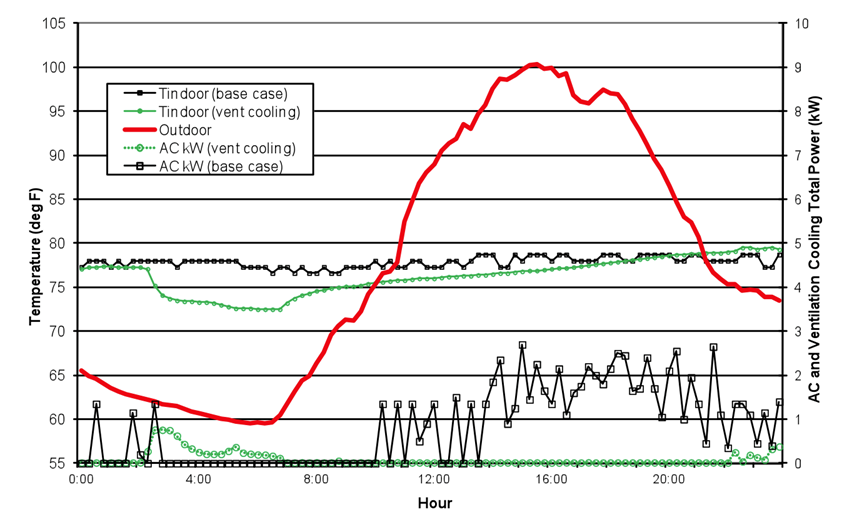
Figure 4-36, above, illustrates how ventilation cooling can offset air conditioning energy use with a relatively small amount of off peak fan energy.
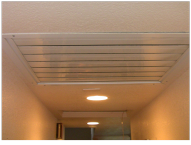
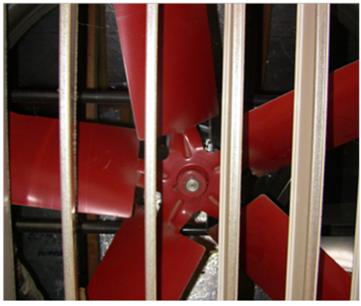
Traditional whole-house fans have a simple barometric damper (Figure 4-37) and either a belt driven or direct-drive motor driving a prop fan. Figure 4-38 shows the damper open with the fan immediately above.
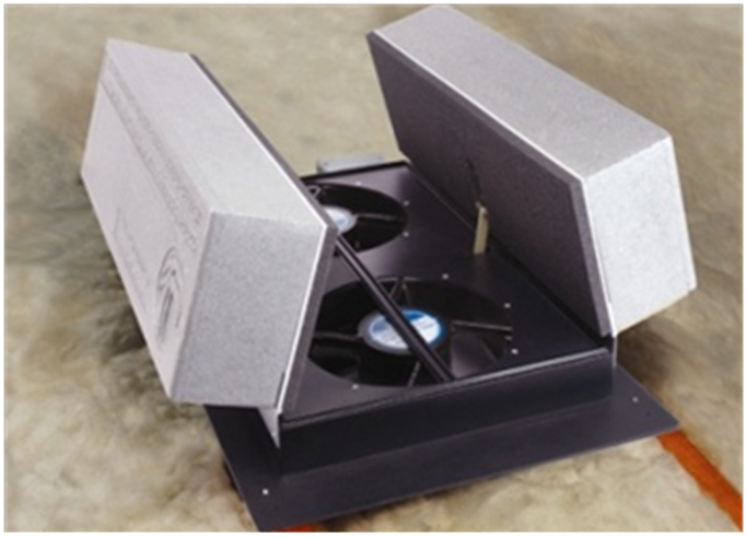
Figure 4-39 shows a similar product that moves less air but provides an insulated damper with a better leakage seal between the attic and conditioned space. These units are generally designed to fit between standard rafter spacing, simplifying retrofit installations.
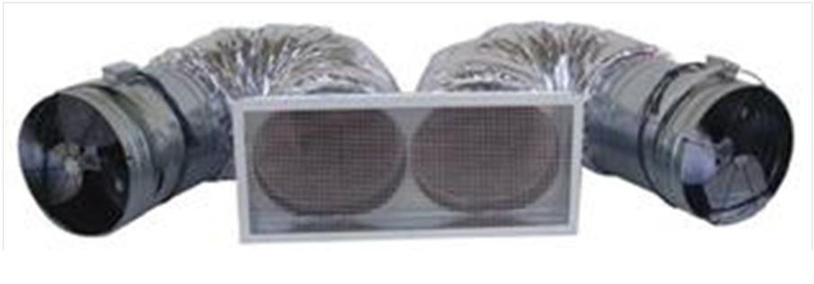
Finally, Figure 4-40 shows remote whole-house fan design that removes the fan farther from indoor space, reducing the noise during operation.
Whole house fans operate most effectively at cooling a space when windows throughout the house are opened to a limited extent to ensure fairly uniform airflow throughout the dwelling. This results in the greatest interaction of the cool air with the interior mass throughout the dwelling, providing the greatest amount of stored cooling. Running the fan all night long is most effective at fully “charging” the thermal mass. Noise can be reduced somewhat through either use of a variable speed control, or installation of a multispeed fan, allowing low speed nighttime operation. Security concerns and added dust and allergens are other factors to consider with the installation of a whole house fan.
The WHFs used to comply with the Standards must be 'listed in the Energy Commission’s Appliance Database which can be accessed at:
www.cacertappliances.energy.ca.gov.
Source: California Energy Commission
Source: California Energy Commission
Source: California Energy Commission
Figure 4–40: Ducted Remote Whole House Fan
Source: California Energy Commission
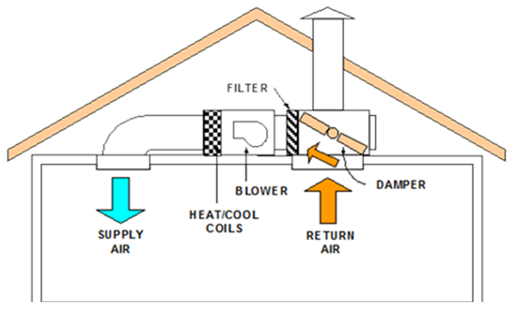
Central fan ventilation cooling systems use the furnace or air handler fan to deliver outdoor air to conditioned space. By adding an automated damper, outside air duct, and temperature sensors and controls, these systems can automatically deliver filtered outdoor air to occupant-specified comfort levels when outdoor conditions warrant the use of ventilation. This automated operation represents an improvement over WHFs, which rely entirely on the occupant being available to initiate operation and open windows throughout the house. A disadvantage of the central fan systems is that they typically move less air and consume more energy per cfm due to the more restrictive duct systems.
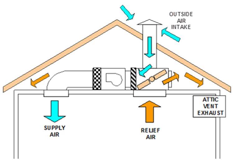
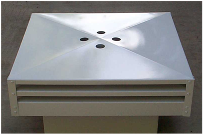
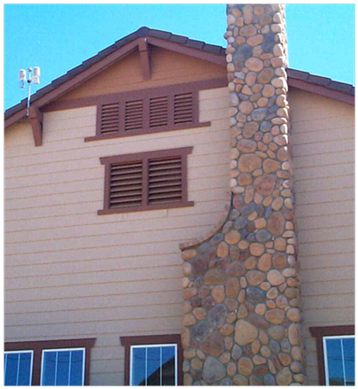
Figure 4-41 and Figure 4-42 show the airflow paths when the systems operate in conventional return air mode or outdoor air mode. In (Figure 4-41), the damper is positioned to direct return air to the air handler for normal heating and cooling operation. In Figure 4-42 (ventilation cooling mode), the damper position is reversed so that air entering the air handler is now pulled from the outside air duct, and then delivered to the house, with relief air exhausted through the damper to the attic. The air intake shown in these figures can be either a roof penetration inlet (as shown in Figure 4-43) or a gable end screen vent as shown in Figure 4-44. A larger diameter duct sized to handle the full ventilation airflow runs from the air inlet to the damper box.
Source: California Energy Commission
Source: California Energy Commission
Several advantages for central fan systems include control integration with the central system thermostat, precise control of ventilation initiation and termination, filtered outdoor air, and increased home security (windows can remain shut). One of the systems currently available also uses a variable speed motor promoting fan speed control in response to outdoor conditions and indoor comfort settings. This has been shown to provide energy savings relative to a fixed speed central fan ventilation system.
Component Package A specifies a whole house fan as a prescriptive requirement for single-family newly constructed buildings in Climate Zones 8 through 14. The whole house fan, or central fan system, must meet the eligibility criteria specified below to meet the prescriptive requirement.
Additions of 1,000 ft2 or less are exempt from the whole house fan prescriptive requirements.
A. Eligibility Criteria for Whole House Fans
1. Whole-house fans must meet combustion air safety requirements related to indoor gas-fired appliances.
2. Whole House Fans modeled for Title 24 credits must be 'listed in the Energy Commission Appliance Database.
3. To meet the prescriptive requirement, the installed whole-house fan(s) must have a 'listed airflow of at least 1.5 cfm/ft2 of house conditioned floor area. The house must have a minimum attic net free vent area to outdoors of one square foot per 750 cfm of installed Whole House Fan(s) rated airflow. See Table 4-20 and 4-21 below for net free ventilation area based on the square footage of the house.
4. Homeowners who have WHFs installed must be provided with a one page “How to operate your whole house fan” informational sheet.
B. Eligibility Criteria for Central Fan Systems
1. Central fan night ventilation systems will be required to meet Title 24 duct leakage requirements (with system operating in return air mode).
2. Central fan night ventilation systems will be required to meet the fan watt draw requirement that involve HERS verification of airflow and fan power, demonstrating an efficacy of no more than 0.58 watts/cfm.
3. In 'addition to sensing temperature at the thermostat, the central fan system must have an outdoor temperature sensor (used to initiate and terminate night ventilation operation) and a temperature sensor sensing the air temperature entering the air handling unit (used for damper position verification).
4. Central fan systems will be treated as “fixed speed” systems, unless the manufacturer can provide documentation to the California Energy Commission that the product demonstrates the criteria 'listed below. The Commission will review the submittal and determine that the system adequately meets the qualifying criteria.
a. The installed fan motor is a variable-speed motor.
b. The motor is controlled in night ventilation mode to vary in a continuous range between full air flow (100 percent) and a minimum airflow of no more than 25 percent of full airflow.
c. The manufacturer will provide written documentation on how its control strategy is implemented, how night ventilation fan speed is controlled, and how ventilation cooling rates are determined. The ventilation cooling rate calculation will occur within a 24-hour interval or less to insure that the system responds in a timely manner to changes in weather patterns.
Table 4-20 shows example conversions for the calculated net free vent area (NFVA) for a range of Energy Commission- listed whole-house fan airflow levels. Instead of using the table, one can calculate the NFVA by dividing the listed cfm by 750.
|
CEC Listed Airflow (cfm) |
Minimum Attic NFVA (ft2) |
|
2000 |
2.7 |
|
3000 |
4 |
|
4000 |
5.3 |
|
5000 |
6.7 |
|
6000 |
8 |
|
7000 |
9.3 |
Source: California Energy Commission
Since attic vents present some level of airflow restriction, use the appropriate screen and louver reduction factor from Table 4-21.
|
Vent Type |
Reduction Factor |
|
¼” screen (hardware cloth) |
0.90 |
|
¼” screen with metal louvers |
0.75 |
|
¼” screen with wood louvers |
0.25 |
|
Insect screen (mesh under ¼”) |
0.50 |
|
Insect screen with metal louvers |
0.50 |
|
¼” screen with wood louvers |
0.25 |
Source: California Energy Commission
Example:4-46
Required vent area = Minimum Attic NFVA (Table 4-20) ÷ Reduction Factor
A 3,000 cfm fan is selected from the Energy Commission Appliance Database. The builder is plans to use vents with “¼” screen with metal louvers”.
Answer: The minimum required vent area is = 4.0 ÷ 0.90 = 4.4 ft2
Example 4-47 – Ventilation Cooling
Question:
I am building a 2,350 ft2 house in Climate Zone 8. Do I need to install a whole house fan or central fan ventilation system?
Answer:
Yes, if you are complying prescriptively.
No, if you are complying using the performance method.
Whole house fans (or eligible central fan systems) are a prescriptive requirement in climate zones 8-14, meaning that they are not mandatory, although they define the prescriptive compliance level. If you decide to install a whole house fan to meet the prescriptive requirement, you should select a fan from the Energy Commission Appliance Database. The prescriptive requirement specifies a minimum airflow of 1.5 cfm/ft2 (525 cfm for the proposed house) and 1 ft2 of attic net free ventilation area per 750 cfm of airflow (4.7 ft2 for a 525 cfm fan).
Example 4-48
Question:
Why do I need to provide attic ventilation area for a whole-house fan?
Answer:
Whole-house fans move a lot of air, all of which is exhausted to the attic. Without sufficient attic relief to the outdoors, the air velocity will increase (potentially disturbing blown insulation), and the fan will move less air.
Example 4-49
Question:
What are the advantages and disadvantages of whole house fans relative to central fan ventilation cooling systems?
Answer:
Whole house fans are relatively inexpensive; both in first cost and operating cost, and are highly effective if used properly in the right climate. They move much more air than central fan systems which must deliver air through the existing duct system. Whole-house fans can be noisy, require user operation to open windows, turn on and off, bring dust and allergens indoors from outside, and potentially reduce home security if operated throughout the night. Central fan systems are more expensive and generally move less air, but provide totally automated operation, independent of whether the occupant is home. Windows can remain shut and all outdoor air is filtered. Some central fan systems may also be configured to provide fresh air ventilation consistent with the mechanical ventilation requirements (Section 4.6). Review product literature to determine if available products meet the Energy Commission fresh air ventilation requirements.
Example 4-50
Question:
A two story home with a 2,500 sf of conditioned space and having an attic of 1,500 sf is located in Climate Zone 10. Are whole-house fans required? Does this affect the number of vents in the attic?
Answer:
Yes
Section 150.1(c)12 requires whole house fans (WHF) in single family houses that are located in Climate Zones 8-14. These are climate zones that have summer cooling needs but where the home can be efficiently cooled on cool summer evenings by the use of a whole-house fan.
Section 150.1(c)12 also requires that these fans be sized so they provide at least 1.5 cubic feet per minute (cfm) of flow for each square foot of conditioned space in the house. The fans used must be 'listed in the Energy Commission’s Appliance Database (http://appliances.energy.ca.gov/QuickSearch.aspx) and the rated cfm 'listed on the CF2R-Mech 02 form. In 'addition, the attic must have at least 1 sf of attic vent free area for each 750 cfm of whole-house fan-rated flow.
Thus, for this house with 2,500 sf of conditioned floor area, the minimum total flow rate of whole house fans installed in the house must be at least:
Min WHF flow rate = Conditioned Floor Area x 1.5 CFM/sf = 2,500 sf x 1.5 cfm/sf = 750 cfm.
In this case, the builder has selected two 2,000 cfm whole house fans. The minimum amount of vent net free area in the attic is calculated as follows:
Net Free Area = Total WHF cfm / (750 cfm/sf NFA) = (2,000 + 2,000) / 750 = 5.3 sf