
As houses have been tightened up over the last several years due to rising energy cost and the availability of higher performing building materials, normal infiltration and exfiltration have significantly reduced. This condition has increased the effect of contaminants and pollutants introduced through common building materials, cleaners, finishes, packaging, furniture, carpets, clothing, and other products. The Energy Standards have always assumed adequate indoor air quality would be provided by a combination of infiltration and natural ventilation and that home occupants would open windows as necessary to make up any shortfall in infiltration. However, Energy Commission-sponsored research on houses built under the 2001 Standards revealed that overall ventilation rates are lower than expected, indoor concentration of chemicals such as formaldehyde are higher than expected, and many occupants do not open windows regularly for ventilation. The 2013 Standards included mandatory mechanical ventilation intended to improve indoor air quality (IAQ) in homes. The 2016 Energy Standards continue this effort.
As specified by §150.0(o), all low-rise residential buildings must meet the requirements of ASHRAE Standard 62.2-2010, including Addenda b, c, e, g, h, i, j, l, and n to ASHRAE 62.2-2010. The exception is that opening and closing windows and continuous operation of central fan-integrated ventilation systems are not allowable options for meeting whole-building ventilation requirements.
The requirements of ASHRAE Standard 62.2 focus on whole-building mechanical ventilation and local ventilation exhaust at known sources of pollutants or moisture, such as kitchens, baths, and laundries. While not required by the Energy Standards, builders and homeowners should select materials, finishes, and furnishings that have no or low emissions of air pollutants, such as formaldehyde and volatile organic compounds (VOCs), because keeping air pollutants out of the building in the first place is more effective than flushing them out later through ventilation.
Most building materials emit some level of VOCs, formaldehyde, or other pollutants, and the resultant indoor pollutants can pose a substantial risk to occupant health. Pollutant emissions are highest immediately after a new product is installed, but emissions may continue for days, weeks, months, or years. Buildup of these air pollutants in the home is affected by ventilation, infiltration, and filtration rates; thus, these rates are addressed by the requirements in ASHRAE Standard 62.2.
The California Air Resources Board (ARB) provides guidance for reducing indoor air pollution in homes. For more information, see the ARB Indoor Air Quality Guidelines:
www.arb.ca.gov/research/indoor/guidelines.htm
This Section will cover compliance and enforcement, typical design solutions, energy consumption issues, and other requirements specified by ASHRAE 62.2.
Compliance with the whole-building ventilation airflow specified in ASHRAE 62.2 is required in new buildings and in buildings with additions greater than 1,000 ft2. All other mechanical ventilation requirements, including local exhaust, must be met (as applicable) in all additions and alterations. Alterations to components of existing buildings that previously met any requirements of ASHRAE 62.2 must continue to meet requirements upon completion of the alteration(s). Individual dwelling units in multifamily buildings are required to each meet the same requirements as single-family dwelling units, except as otherwise described in Section 4.6.8.
The following summarizes the key requirements for most newly constructed buildings:
1. A whole-building mechanical ventilation system shall be provided. The typical solutions are described in the Section 4.6.2 below. The airflow rate provided by the system shall be confirmed through field verification and diagnostic testing in accordance with the applicable procedures specified in Reference Residential Appendix RA3.7.
2. Kitchens and bathrooms shall have local exhaust systems vented to the outdoors.
3. Clothes dryers shall be vented to the outdoors.
Miscellaneous indoor air quality design requirements apply, including the following:
1. Ventilation air shall come from outdoors and shall not be transferred from adjacent dwelling units, garages, or crawl spaces.
2. Ventilation system controls shall be labeled, and the homeowner shall be provided with instructions on how to operate the system.
3. Combustion appliances shall be properly vented, and exhaust systems shall be designed to prevent back drafting.
4. The walls and openings between the house and the garage shall be sealed.
5. Habitable rooms shall have windows with a ventilation area of at least 4 percent of the floor area.
6. Mechanical systems including heating and air-conditioning systems that supply air to habitable spaces shall have MERV 6 filters or better and be designed to accommodate the system's air filter media rated pressure drop for the system design airflow rate.
7. Dedicated air inlets (not exhaust) that are part of the ventilation system design shall be located away from known contaminants.
8. A carbon monoxide alarm shall be installed in each dwelling unit in accordance with NFPA Standard 720.
9. Air-moving equipment used to meet the whole-building ventilation requirement and the local ventilation exhaust requirement shall be rated in terms of airflow and sound:
a. All continuously operating fans shall be rated at a maximum of 1.0 sone.
b. Intermittently operated whole-building ventilation fans shall be rated at a maximum of 1.0 sone.
c. Intermittently operated local exhaust fans shall be rated at a maximum of 3.0 sone.
Remotely located air-moving equipment (mounted outside habitable spaces) need not meet sound requirements if there is at least 4 feet of ductwork between the fan and the intake grille.
Compliance with ASHRAE 62.2 requirements must be verified by the enforcement agency, and the whole-building ventilation airflow rate must be verified by a HERS Rater in accordance with the procedures in Residential Appendix RA3.7. The applicable certificates of compliance, installation, and verification must be registered with an approved HERS Provider.
If a central heating/cooling system air-handler fan is used to ventilate the dwelling (central fan integrated ventilation), the air handler must meet or exceed the mandatory fan efficacy criteria. This requires the installer to perform the test given in Reference Appendix RA3.3, and a HERS Rater to verify the performance of the air handler.
When the performance compliance approach is used, the required whole-building ventilation airflow is calculated based on the total conditioned floor area (CFA) and the number of bedrooms. (See Section 4.6.3.1A.) Therefore, it is important that these values are input into the compliance software correctly and checked by the plans examiner. The performance certificate of compliance (CF1R) will report:
the Required ventilation airflow rate (calculated value) that must be delivered by the system.
System type selected (that is, exhaust, supply, balanced, CFI).
Fan power ratio (watts/CFM) for the selected system.
The requirement of HERS verification of fan watt draw for the air handler when a CFI ventilation system is being used.
The installed whole-building ventilation system must conform to the performance requirements on the CF1R. For more information about the performance calculations for whole-building ventilation systems, see Section 4.6.4. There are no requirements to describe fans installed for other purposes such as local exhaust on the performance CF1R.
When using the prescriptive compliance approach, information that describes the whole-building ventilation system is not required on the CF1R. Unless otherwise required by the enforcement agency, calculation of the required ventilation airflow rate and selection of the system type can be done at installation. There are no requirements to describe fans installed for other purposes, such as local exhaust, on the prescriptive CF1R.
The enforcement agency may require additional information/documentation describing the ventilation systems be submitted along with the CF1R at plan check.
The builder/installer must complete a certificate of installation (CF2R-MCH-27) for the dwelling. The HERS Rater must complete a certificate of verification (CF3R-MCH-27) for the dwelling.
The following information must be provided on the CF2R-MCH-27 and CF3R-MCH-27 to document compliance with §150.0(o):
Required whole-building ventilation airflow rate for continuous or intermittent operation as specified by ASHRAE 62.2 equations. (See Section 4.6.3.)
Installed system type (that is, exhaust, supply, balanced, CFI).
Measured airflow rate of the installed whole-building ventilation system.
Confirmation from the builder/installer that the other applicable requirements given in ASHRAE 62.2 have been met. (See Sections 4.6.5) and 4.6.6.)
There are three typical solutions for meeting the outside air ventilation requirement:
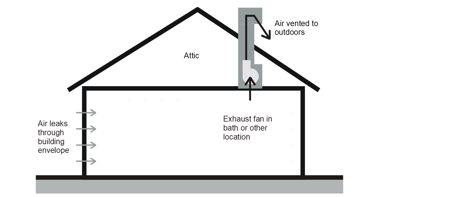
1. Exhaust ventilation.
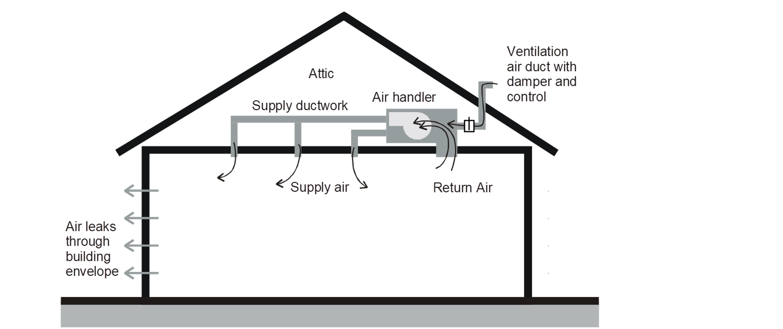
2. Supply ventilation.
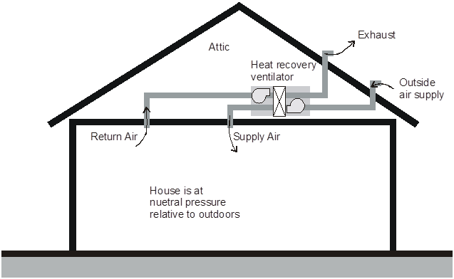
3. Combination of supply and exhaust ventilation. (If the supply and exhaust flows are within 10 percent of each other, this is called a “balanced ventilation system”.)
Whole-building ventilation may be achieved through a single fan or a system of fans that are dedicated to whole-building ventilation only or by fans that also provide local exhaust or distribute heating and cooling.
Source: California Energy Commission
Exhaust ventilation is usually achieved by a quiet ceiling-mounted bath fan or remote-mounted inline or exterior-mounted fan. Air is drawn from the house by the exhaust fan and outdoor air enters the house through infiltration.
Many high quality bath fans are available in the 30 to 150-cfm size range are quiet enough to be used continuously. One or more fans of this size will meet the requirements of most homes. The exhaust fan can be a dedicated IAQ fan or a typical bath fan that is used for both whole-building ventilation and local ventilation.
Inline fans (either single pickup or multipoint pickup) can be a very effective method of providing quiet exhaust ventilation from one or several bathrooms. Inline fans can be located in the garage, attic, basement, or mechanical room.
Exterior-mounted fans can be mounted on the exterior wall or on the roof. A sound rating is not required for remote or exterior fans with at least 4 ft of duct between the closest pickup grille and the fan.
Source: California Energy Commission
Supply ventilation works by bringing outside air into the house through a dedicated supply fan or the central forced-air system air handler and escapes through exfiltration.
The air handler or supply the outdoor air inlet should avoid areas contaminants, such as garages, barbeque areas, and chimneys. If a dedicated fan is used, care must be taken to avoid introducing too much outdoor air into one location and creating uncomfortable conditions. The ventilation air can be distributed by a dedicated duct system separate from the central forced air distribution duct system.
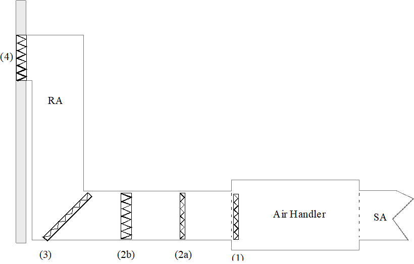
Alternatively, the central forced-air system air handler can be configured to function as a ventilation supply system by installing a dedicated ventilation air duct that connects to the return plenum of the air handler and to the dwelling exterior. This strategy, called central fan integrated (CFI) ventilation, uses negative pressure in the return plenum to pull outdoor air in through the ventilation air duct and into the return plenum, then the central system air handler distributes the ventilation air through the house. A damper and controls must be installed that ensure the air handler delivers the required ventilation airflow regardless of the size of the heating or cooling load.
When considering design and compliance for CFI ventilation systems, it is important to distinguish between the central forced-air system fan total airflow and the much smaller ventilation airflow (the airflow that is induced to flow into the return plenum from outdoors). Refer to Figure 4-29 and note that the total airflow through the air handler is the sum of the return airflow and the ventilation airflow.
ASHRAE Standard 62.2, Section 4.3 requires the installer to measure the ventilation airflow rate in a CFI system in all operation modes to ensure that it will meet the ventilation rate requirements, regardless of whether the system operates to provide heating or cooling. Because §150.0(o) specifically prohibits continuously operating the central forced air system with CFI ventilation systems, CFI systems must be intermittent. The results of the airflow measurement of the installed CFI system and the intermittent ventilation control schedule used for the CFI system must be given on the Certificate of Installation. The whole-house ventilation rate must also be verified by a HERS Rater.
The outside air (OA) ducts for CFI ventilation systems cannot be sealed/taped off during duct leakage testing. However, CFI OA ducts that use controlled motorized dampers that open only when OA ventilation is required and close when OA ventilation is not required may be closed during duct leakage testing.
CFI ventilation systems can use a very significant amount of electricity annually. Air handlers used in CFI ventilation systems are required to meet the prescriptive fan watt draw requirements in all climate zones.
Source: California Energy Commission
Combination systems use both exhaust fans and supply fans. If both fans supply the same airflow, the system is balanced, and the house has a neutral pressure.
Combination systems are often integrated devices, sometimes with a heat exchanger or heat recovery wheel. The supply and exhaust airstreams are typically of equal flow.
Combination systems can also be a mixture of supply fans and exhaust fans. It may be as simple, such as a quiet continuous bathroom exhaust fan matched to an outdoor air connection that introduces air into the return air plenum of a continuously operating central heating/cooling system air handler.
Note: Ventilation systems that constantly operation the central heating/cooling system air handler can use a very significant amount of electricity annually and are not permitted by the Energy Standards.
The whole-building ventilation system may operate continuously or intermittently. The whole-building ventilation rate is determined for continuous ventilation: if the system is operated intermittently, an adjustment is made.
There are two strategies for determining the continuous whole-building ventilation rate: the fan ventilation rate method, which assumes that all required ventilation will be provided mechanically, and the total ventilation rate method, which assumes that ventilation will be achieved by a combination of natural infiltration and mechanical ventilation.
Both methods are allowed for newly constructed homes and alterations. The fan ventilation rate method may be advantageous from a design perspective because the infiltration rate of the house does not need to be determined before construction. In either case, a fan system must be designed and installed that meets the whole-building ventilation airflow requirements, however it is determined.
A. Fan Ventilation Rate Method
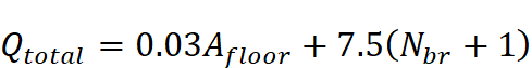
The continuous whole-building ventilation rate is 1 cfm for each 100 ft² of conditioned floor area plus 7.5 cfm for each occupant. The number of occupants is calculated as the number of bedrooms plus one. For example, a three bedroom house is assumed to have four occupants. The required ventilation rate is given by the following Equation 4-1.
Equation 4-1
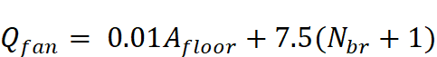
Where:


Instead of using one of the equations given above, Table 4-14 may be used to determine the required ventilation. This table allows the user to find the required ventilation rate directly if he or she knows the floor area and number of bedrooms.
To comply with ASHRAE 62.2 the delivered airflow of the whole house ventilation fan must be greater than or equal to the required ventilation rate (cfm) from either Table 4-14 or Equation 4-1.
|
Conditioned Floor Area (ft²) |
Bedrooms | ||||
|
0-1 |
2-3 |
4-5 |
6-7 |
>7 | |
|
≤1500 |
30 |
45 |
60 |
75 |
90 |
|
1501-3000 |
45 |
60 |
75 |
90 |
105 |
|
3001-4500 |
60 |
75 |
90 |
105 |
120 |
|
4501-6000 |
75 |
90 |
105 |
120 |
135 |
|
6001-7500 |
90 |
105 |
120 |
135 |
150 |
|
>7500 |
105 |
120 |
135 |
150 |
165 |
Source: ASHRAE 62.2
Example 4-6 – Required Ventilation
Question:
What is the required continuous ventilation rate for a three bedroom, 1,800 ft² townhouse?
Answer:
Equation 4-1 gives a required ventilation rate of 48 cfm:

Table 4-14 gives a required ventilation rate of 60 cfm.
Example 4-7
Question:
The house has a floor area of 2,240 ft² and three bedrooms. My calculations come out to 52.4 cfm. Can I use a 50 cfm fan?
Answer:
No, A 50 cfm fan does not meet the standard.
Also, note that the nominal rating of a fan can be very different than what a fan actually delivers when installed. Actual airflow depends greatly on the length and size of the duct needed to get the air outside. Proper fan sizing requires more detailed manufacturer’s data, such as airflow vs. static pressure. This is why whole-building ventilation rates must be verified by a HERS Rater.
A. Total Ventilation Rate Method
This method for determining a continuous whole-building ventilation rate starts with calculating the total ventilation rate, which consists of both the natural and mechanical ventilation rates.
The total ventilation rate is calculated using an equation similar to that used in the fan ventilation rate method. Next, the natural ventilation (infiltration) rate is calculated from diagnostically tested values.
The infiltration rate is subtracted from the total ventilation rate, leaving the ventilation rate that must be provided mechanically.
The equation for calculating the total ventilation rate is:
Equation 4-2
Where:

2)
The number multiplied times the floor area is three times greater than that used in Equation 4-1.
The ventilation rate associated with infiltration is calculated using an effective leakage area (ELA) value that must be diagnostically verified in the field.
The ELA value used for these equations is in square feet, not square inches as may be the case in other equations.
RA3.8 covers the protocols for blower door testing for verifying infiltration for reduced infiltration compliance credit. Unless specifically directed otherwise in this section, RA3.8 shall be met.
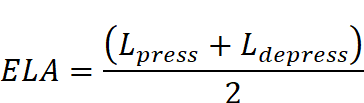
Because infiltration can occur by air coming into the home as well as air going out of the home, it is more accurate to measure ELA under depressurization and pressurization (using a 4 Pa reference pressure), then average the two values using Equation 4-3.
Equation 4-3
Where:
 2)
2)
 2)
2)
 2)
2)
When designing for a house that is not built yet, the ELA values will be estimated numbers. If the actual (measured) number is different, the ventilation system design may need to be modified to comply.
The leakage is normalized based on the area of the house and the potential for stack effect using Equation 4-4.
Equation 4-4
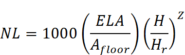
Where:

2)
2)


The effective annual infiltration rate is then calculated using Equation 4-5. This is the amount of infiltration that is considered to offset the need for fan-powered ventilation.
Equation 4-5
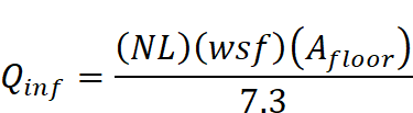
Where:


2)
The ventilation rate required by the fan is then calculated by subtracting the infiltration ventilation rate from the total ventilation rate.
Equation 4-6
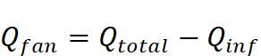
Where:
For well-sealed houses, the fan ventilation rate calculated using the total ventilation rate method may be higher than that calculated by the fan ventilation rate method, so it is worth checking both.
No whole-building ventilation is required if
C. Ventilation Rate for Combination Systems
When a combination ventilation system is used, meaning that both supply and exhaust fans are installed, the provided ventilation rate is the larger of the total supply airflow or the total exhaust airflow. The airflow rates of the supply and exhaust fans cannot be added together to determine the provided ventilation rate.
Example 4-8
Question:
A 2,400 ft² house has exhaust fans running continuously in two bathrooms providing a total exhaust flow rate of 40 cfm, but the requirement is 60 cfm. What are the options for providing the required 60 cfm?
Answer:
The required 60 cfm could be provided either by increasing the exhaust flow by 20 cfm or by adding a ventilation system that blows 60 cfm of outdoor air into the building. It cannot be achieved by using a make-up air fan blowing 20 cfm into the house.
In some cases, it may be desirable to design a whole-building ventilation system that operates intermittently. One common example of intermittent ventilation is when outside air is ducted to the return plenum of the central heating/cooling system, and thus the central heating/cooling system fan is used to distribute the ventilation air to the rooms in the building (See CFI system described above in the supply ventilation section).
Intermittent mechanical ventilation systems, devices, or controls may be approved for use for compliance with the HERS field verification requirements for whole-building mechanical ventilation airflow. A listing of certified intermittent mechanical ventilation systems is posted at the following URL.
www.energy.ca.gov/title24/equipment_cert/imv/
Intermittent ventilation is permitted as long as the ventilation airflow is increased to respond to the fewer hours of fan operation and the tendency of pollutant concentrations to build up during off cycles.
Equation 4-7
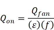
Where:


To obtainTable
4-15, the required turnover,
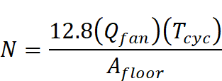
Where
Table
4-14 or Equation 4-1(cfm)

2)
The maximum allowable
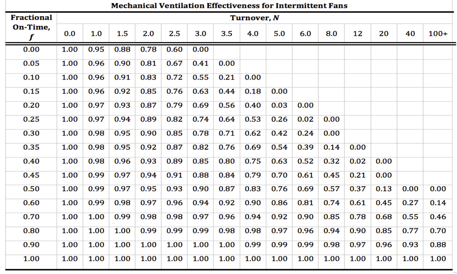
Source: ASHRAE 62.2
Intermittent ventilation systems must be automatically controlled by a timer or other device that assures they will operate the minimum amount of time needed to meet the ventilation requirement. The scheduling of the automatic controls must be such that the fan operates at least 10 percent of the time and that a single on/off cycle occurs at least once per day.
Example 4-9 – Flowrate for Intermittent Fan
Question:
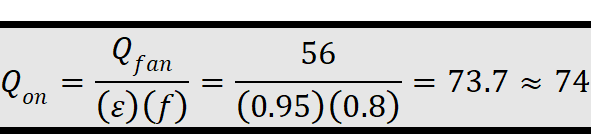
The required ventilation rate is 56 cfm. If the ventilation fan runs for 80 percent of the day, what must the airflow rate be for a 2600 ft² townhouse?
Answer:

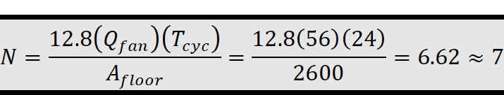
From Table
4-15,
Example 4-10
Question:
For the same house, if the fan runs half the day (12 hours per day), what is the required airflow?
Answer:
The
fractional on-time, 

From Table
4-15,
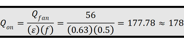
This is a much larger increase in fan size. More than double the fan size over Example 4-10 is required to move the same amount of air, even though the on-cycle was only decreased by less than half. In many designs, it may be better to consider a lower power, quieter fan that will run for longer over a high power fan that will run for a shorter period.
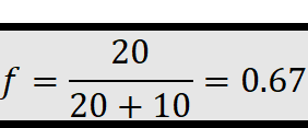
Example 4-11
Question:
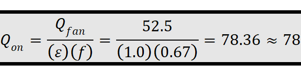
A three-bedroom, 2250 ft² apartment, the flow required is 52.5 cfm. If the ventilation fan runs 20 minutes on and 10 minutes off, what is the required fan size?
Answer
Fractional on-time is 0.67:
The required turnover is calculated to be 0.149 using Equation 4-8:
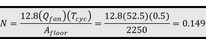
From Table
4-15,
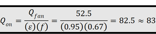
Example 4-12
Question:
For the same apartment, if the fan runs 8 hours on and 4 hours off, what flow rate is required?
Answer:
Fractional
on-time is again 0.67, but

From Table
4-15,
Example 4-13
Question:
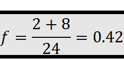
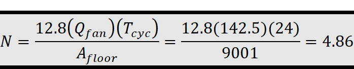
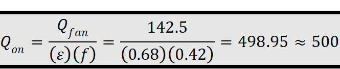
An electronic timer system on a 9001 ft² estate with 6 bedrooms can be set to operate a fan for 1 minute every hour. The timer runs the fan 2 hours in the morning and 8 hours in the evening. What is the required intermittent flow rate?
Answer:
The scheduling of the automatic controls must be such that the fan operates at least 10 percent of the time and that a single on/off cycle occurs at least once per day. An on/off cycle of 1 minute every hour is only 1.67 percent and does not meet this requirement.
Equation 4-1
gives a required ventilation rate of 142.5 cfm ( Table
4-14 would be 150 cfm):
Table
4-14 would be 150 cfm):

The fractional on-time for a fan running 2 hours in the morning and 8 hours in the evening is equivalent to 0.42:
The required turnover is calculated to be 4.86 using Equation 4-8:
From Table
4-15,
4.6.3.3
Control and Operation
From ASHRAE
62.2
Section 4.4 Control and Operation
The
“fan on” switch on a heating or air-conditioning system shall be permitted as an
operational control for systems introducing ventilation air through a duct to
the return side of an HVAC system. Readily accessible override control must be
provided to the occupant. Local exhaust fan switches and “fan on” switches shall
be permitted as override controls. Controls, including the “fan-on” switch of a
conditioning system, must be appropriately labeled.
Exception: An
intermittently operating, whole-house mechanical ventilation system may be used
if the ventilation rate is adjusted, according Section 4.5.1. The system must be
designed so that it can operate automatically based on a timer. The intermittent
mechanical ventilation system must operate at least once per day and must
operate at least 10% of the time.
ASHRAE 62.2 requires that the ventilation system have an override control that is readily accessible to the occupants. The control must be capable of being accessed quickly and easily by the occupants without having to remove panels or doors. It can be a labeled wall switch by the electrical panel or it may be integrated into a labeled wall-mounted control. It cannot be buried in the insulation in the attic or the inside the fan. The occupant must be able to modify the settings or override the system.
If intermittent fans are used, they must be controlled by a timer, and they must have an increased airflow rate to compensate for the off time.
Time-of-day timers or duty cycle timers can be used to control intermittent whole-building ventilation. Manual crank timers cannot be used, since the system must operate automatically without intervention by the occupant. Some controls “look back” over a set time interval to see if the air handler has already operated for heating or cooling before it turns on the air handler for ventilation only operation.
Example 4-14 – Control Options
Question:
A bathroom exhaust fan is used to provide whole-building ventilation for a house. The fan is designed to be operated by a typical wall switch. Is a label on the wall plate necessary to comply with the requirement that controls be “appropriately labeled”?
Answer:
Yes. Since the fan is providing the required whole-building ventilation, a label is needed to inform the occupant that the fan should be operating whenever the home is occupied. If the exhaust fan were serving only the local exhaust requirement for the bathroom, then a label would not be required.
Example 4-15 – Thermostatic Control
Question:
Ventilation air is provided whenever the air handler operates via a duct run connecting the return side of the central air handler to the outdoors. The system is estimated to run on calls for heating and cooling about 40 percent of the time, averaged over the year. If it is assumed that the air handler only runs 25 percent of the time, and the airflow is sized accordingly, can the system be allowed to run under thermostatic control?
Answer:
No.
A system under thermostatic control will go through periods with little or no operation when the outdoor temperature is near the indoor setpoint, or if the system is in setback mode. An intermittently operating ventilation system must be controlled by a timer that will cycle at least once within 24 hours to assure that adequate ventilation is provided regardless of outdoor conditions.
Cycle timer controls are available that function to keep track of when (and for how long) the system operates to satisfy heating/cooling requirements in the home. These controls turn on the central fan to provide additional ventilation air when heating/cooling operation of the central fan has not already operated enough to provide the required ventilation.
As mentioned in the text, there are timer based controls available that function to keep track of when (and for how long) the system operates to satisfy heating/cooling requirements in the home. These controls only turn on the central fan to provide additional ventilation air when heating/cooling operation of the central fan has not already operated enough to provide the required ventilation.
For builders using the performance compliance approach, the energy use of fans (other than CFI fans) installed to meet the whole-building ventilation requirement is usually not an issue. The reason is the standard design W/CFM is set equal to the proposed design W/CFM up to an energy use level sufficient to accommodate most well-designed ventilation systems. Also, the standard design whole-building ventilation system airflow rate is set equal to the proposed design whole-building ventilation system airflow rate, so there is no energy penalty or credit for most systems. Systems that use heat recovery or energy recovery ventilators (HR/ERV) may need to account for the heat recovery benefit in the performance calculation to make up for the high energy use.
The energy use of the central air handler fan used for a CFI ventilation system must conform to the same fan watt draw (W/CFM) limit as for cooling systems in all climate zones. CFI systems are the only type of ventilation system that must meet a prescriptive fan watt draw requirement that must be tested by the builder/installer and verified by a HERS Rater in accordance with the diagnostic test protocols given in RA3.3
Energy use of fans installed for other purposes, such as local exhaust, is not regulated in the Energy Standards.
CFI system automatic controls must operate the central system air handler fan (generally part of every hour of the year) to draw in and/or distribute ventilation air around the home even when there is no heating or cooling required. CFI systems generally do not operate continuously, thus do not meet the whole-building ventilation requirement as a “continuous" system. Because the CFI ventilation control increases the central system air handler fan run time significantly, and because typical central system air handler fan and duct systems require a large amount of power, a CFI ventilation system can use a very significant amount of electricity annually.
The Energy Standards include mandatory requirements for ducted central cooling system air handlers to comply with maximum fan watt draw targets. The watt draw requirement also applies to any ducted central system air handler used for a CFI system. Compliance with this requirement involves a post construction measurement by the installing contractor of the airflow through the air handler, and the simultaneous measurement of the watt draw of the air handler fan motor. This fan watt draw measurement must be measured by the installer and verified by a HERS Rater. (See Reference Residential Appendix RA3.3.) The central system air handler must be operating in ventilation mode (outdoor air damper is open and ventilation air is flowing into the return plenum from outside the building). Furthermore, the airflow that must be measured is the total airflow through the air handler (system airflow), which is the sum of the return airflow, and the outside air ducted to the return plenum (ventilation airflow). To pass the test, the watt draw must be less than 0.58 W/CFM.
Builders who use CFI systems and comply using the performance approach have the option of accepting the default value for the central system fan watt draw of 0.8 W/CFM, which does not require a post construction measurement and HERS verification. Alternatively, the builder can specify a lower W/CFM value for compliance, which must be tested and verified by a HERS Rater. In either case the compliance software will check the furnace fan heating and cooling operation every hour, and if the air handler has not been operating for at least 20 minutes during that hour, the software will calculate energy use for operation in CFI mode until 20 minutes of fan operating occurs. The standard design ventilation energy consumption for that hour will be calculated as the extra fan run time at a watt draw of 0.58 W/CFM. The proposed design ventilation energy for that hour will be calculated as the extra fan run time at the watt draw that was specified for compliance, otherwise at the default Watt draw of 0.8 W/CFM.
There are no prescriptive or mandatory requirements for maximum fan energy (watt draw) for whole-building ventilation systems other than CFI systems.
Builders who specify other whole-building ventilation systems and comply using the performance approach have the option of accepting the default minimum whole-building ventilation airflow rate and a watt draw value of 0.25 W/CFM which is typical of simple exhaust fans that meet the 1 sone requirement. Otherwise, the airflow rate and fan watt draw of the fan may be input. If the builder installs a whole-building ventilation system that has a fan watt draw specification greater than 1.2 W/CFM of ventilation airflow, then he or she must input the ventilation airflow (CFM) and watt draw (W/CFM) corresponding to the system that he or she proposes to install. The compliance software will simulate whole-building ventilation using the builder’s specified ventilation CFM and W/CFM for the proposed design. For the standard design, the builder’s proposed CFM and 1.2 W/CFM will be used. If the builder specifies a system with heat recovery he inputs the recovery, he or she inputs the recovery efficiency of the proposed system and the compliance software uses it in the proposed design to calculate the heating and cooling effect of the whole-building ventilation. Ventilation heat recovery is never used in the standard design.
Local exhaust (sometimes called spot ventilation) has long been required for bathrooms and kitchens to deal with moisture and odors at the source. Building codes have required an operable window or an exhaust fan in baths for many years and have generally required kitchen exhaust either directly through a fan or indirectly through a ventless range hood and an operable window. The Energy Standards recognize the limitations of these indirect methods of providing ventilation to reduce moisture and odors and requires that these spaces be mechanically exhausted directly to outdoors, even if windows are present. As tighter homes with more insulation are built, the relative humidity in the home has increased and the potential for condensation on cool or cold surfaces has increased as well. The presence of moisture condensation has been a leading cause of mold and mildew in both new and existing construction. The occurrence of asthma has also increased as the interior relative humidity has gotten higher. Therefore, it has become more important to remove the moisture from bathing and cooking right at the source.
The Energy Standards require that each kitchen and bathroom have a local exhaust system installed. Generally, this will be accomplished by installing a dedicated exhaust fan in each room that requires local exhaust, although ventilation systems that exhaust air from multiple rooms using a duct system connected to a single ventilation fan are allowed as long as the minimum local ventilation airflow rate requirement is met in all rooms served by the system. The standards define kitchens as any room containing cooking appliances, and bathrooms are rooms containing a bathtub, shower, spa, or other similar source of moisture. A room containing only a toilet is not required by the Energy Standards to have mechanical exhaust; it assumes that there will be an adjacent bathroom that will have local exhaust.
The Energy Standards allow the designer to choose between intermittent operation or continuous operation for the local exhaust ventilation system. The ventilation rates are different because the ventilation effectiveness of an intermittent operation fan is different than the ventilation effectiveness of a continuous operation fan.
Building codes may require that fans used for kitchen range hood ventilation be safety-rated by UL or some other testing agency for the particular location and/or application. Typically, these requirements address the fire safety issues of fans placed within an area defined by a set of lines at 45° outward and upward from the cooktop. Few “bath” fans will have this rating and cannot be used in this area of the kitchen ceiling.
Example 4-16 – Local Exhaust Required for Toilet
Question:
I am building a house with 2½ baths. The half bath consists of a room with a toilet and sink. Is local exhaust required for the half bath?
Answer:
No. Local exhaust is required only for bathrooms, which are defined by the Energy Standards as rooms with a bathtub, shower, spa or some other similar source of moisture. This does not include a simple sink for occasional hand washing.
Example 4-17
Question:
The master bath suite in a house has a bathroom with a shower, spa and sinks. The toilet is in a separate, adjacent room with a full door. Where do I need to install local exhaust fans?
Answer:
The standards require local exhaust only in the bathroom, not the separate toilet room.
The Energy Standards require that intermittent local exhaust fans be designed to be operated by the occupant. This usually means that a wall switch or some other type of control is accessible and obvious. There is no requirement to specify where the control or switch needs to be located, but bath fan controls are generally located next to the light switch, and range hood or downdraft fan controls are generally integrated into the range hood or mounted on the wall or counter adjacent to the range hood.
Bathrooms can use a variety of exhaust strategies. They can use typical ceiling bath fans or may use one or two pickups for remote inline or exterior-mounted fans or heat recovery products. Intermittent local exhaust can be integrated with the whole-building ventilation system to provide both functions. Kitchens can have range hoods, down-draft exhausts, ceiling fans, wall fans, or pickups for remote inline or exterior-mounted fans. Generally, HVR/ERV manufacturers will not allow kitchen pickups to avoid the issue of grease buildup in the heat exchange core. Building codes typically require that the kitchen exhaust must be exhausted through metal ductwork for fire safety.
Example 4-18 – Ducting Kitchen Exhaust to the Outdoors
Question:
How do I know what kind of duct I need to use? I’ve been using recirculating hoods my entire career, now I need to vent to outdoors. How do I do it?
Answer:
Kitchen range hood or downdraft duct is generally a smooth metal duct that is sized to match the outlet of the ventilation device. It is often a six-inch or seven-inch-round duct, or the range hood may have a rectangular discharge. If it is rectangular, the fan will typically have a rectangular-to-round adapter included. Always use a terminal device on the roof or wall that is sized to be at least as large as the duct. Try to minimize the number of elbows used.
Example 4-19
Question:
How do I know what the requirements are in my area?
Answer:
Ask your enforcement agency for that information. Some enforcement agencies will accept metal flex, some will not.
A. Control and Operation for Intermittent Local Exhaust
The choice of control is left to the designer. It can be an automatic control like an occupancy sensor or a manual switch. Some products have multiple speeds and some switches have a delay-off function that continues the exhaust fan flow for a set time after the occupant leaves the bathroom. New control strategies continue to come to the market. The only requirement is that there is a control. Title 24, Part 11 may specify additional requirements for the control and operation of intermittent local exhaust.
B. Ventilation Rate for Intermittent Local Exhaust
A minimum intermittent ventilation airflow of 100 cfm is required for the kitchen range hood, and a minimum intermittent ventilation airflow of 50 cfm is required for the bath fan.
The 100 cfm requirement for the range hood or microwave/hood combination is the minimum to adequately capture the moisture and other products of cooking and/or combustion. The kitchen exhaust requirement can also be met with either a ceiling or wall-mounted exhaust fan or with a ducted fan or ducted ventilation system that can provide at least five air changes of the kitchen volume per hour. Recirculating range hoods that do not exhaust pollutants to the outside cannot be used to meet the requirements of the ASHRAE Standard 62.2 unless paired with an exhaust system that can provide at least five air changes of the kitchen volume per hour.
Most range hoods provide more than one speed, with the high speed at 150 cfm or more – sometimes much more. Range hoods are available that are rated for 1,000 or 1,500 cfm on high speed and are often specified when large commercial-style stoves are installed. Care must be taken to avoid backdrafting combustion appliances when large range hoods are used. Refer to Table 5.1 in ASHRAE 62.2 for intermittent local ventilation exhaust airflow rates and to Section 6.4 in ASHRAE 62.2 for makeup air requirements associated with large exhaust appliances.
Example 4-20 – Is an Intermittent Range Hood Required?
Question:
I am building a house with a kitchen that is 12 ft x 14 ft with a 10 ft ceiling. What size ceiling exhaust fan is required?
Answer:
The kitchen volume is 12 ft x 14 ft x 10 ft = 1680 ft3. five air changes are a flow rate of 1680 ft³ x 5/ hr ÷ 60 min/hr = 140 cfm. So this kitchen must have a ceiling or wall exhaust fan of 140 cfm or a 100 cfm vented range hood.
The Energy Standards allow the designer to install a local exhaust system that operates without occupant intervention continuously and automatically during all occupiable hours. Continuous local exhaust is generally specified when the local exhaust ventilation system is combined with a continuous whole-building ventilation system. For example, if the whole-building exhaust is provided by a continuously operating exhaust fan located in the bathroom, this fan satisfies the local exhaust requirement for the bathroom. The continuous local exhaust may also be part of the continuous whole-building ventilation system, such as a pickup for a remote fan or HRV/ERV system.
Continuously operating bathroom fans must operate at a minimum of 20 cfm and continuously operating kitchen fans must operate at five air changes per hour. These continuous ventilation airflow rates are different than the ventilation airflow rates required for intermittent local exhaust. Refer to Table 5.2 in ASHRAE 62.2 for continuous local ventilation exhaust airflow rates.
The requirement that continuous kitchen exhaust fans must provide five air changes per hour is due to the difficulty of a central exhaust to adequately remove contaminants released during cooking from large kitchens, have an open-plan design, or have high ceilings. The only way to avoid a vented kitchen hood is to provide more than five air changes per hour of constant local exhaust ventilation.
Example 4-21 – Continuous Kitchen Exhaust
Question:
The kitchen in an apartment is 5 ft. by 10 ft., with an 8 ft ceiling. If a continuous ceiling-mounted exhaust fan is used, what must the airflow be?
Answer:
The kitchen volume is 5 ft x 10 ft x 8 ft = 400 ft3. 5 air changes equates to 400 ft³ x 5/hr ÷ 60 min/hr = 34 cfm.
Example 4-22
Question:
A new house has an open-design 12 ftx18 ft ranch kitchen with 12 ft cathedral ceilings. What airflow rate will be required for a continuous exhaust fan?
Answer: The kitchen volume is 12 ft x 18 ft x 12 ft = 2592 ft³. The airflow required is 2592 ft³ x 5/hr ÷ 60 min/hr = 216 cfm.
From ASHRAE 62.2
Adjacent Spaces. Measures shall be taken to minimize air movement across envelope components to occupiable spaces from garages, unconditioned crawl spaces, and unconditioned attics. Supply and balanced ventilation systems shall be designed and constructed to provide ventilation air directly from the outdoors.
8.4.1 Transfer Air. Measures shall be taken to minimize air movement across envelope components separating dwelling units, including sealing penetrations in the common walls, ceilings, and floors of each unit and by sealing vertical chases adjacent to the units. All doors between dwelling units and common hallways shall be gasketed or made substantially airtight
ASHRAE Standard 62.2 requires that the air used for ventilation come from the outdoors. Air may not be drawn in as transfer air from other spaces that are outside the occupiable space of the dwelling unit, or from between dwelling units and corridors This is to prevent airborne pollutants originating in those other spaces from contaminating the dwelling unit. For example, drawing ventilation air from the garage could introduce VOCs or pesticides into the indoor air. Drawing ventilation air from an unconditioned crawlspace could cause elevated allergen concentrations in the dwelling such as mold spores, insects or rodent allergens. Likewise, drawing air from an adjacent dwelling could introduce unwanted contaminants such as cooking products or cigarette smoke.
In 'addition to designing the ventilation system to draw air from the outdoors, the standard also requires that measures be taken to prevent air movement between adjacent dwelling units and between the dwelling unit and other nearby spaces, such as garages. The measures can include air sealing of envelope components, pressure management, and use of airtight recessed light fixtures. The measures must apply to adjacent units both above and below, as well as side by side.
Air sealing must include pathways in vertical components such as demising walls and walls common to the unit and an attached garage, and in horizontal components such as floors and ceilings. Pipe and electrical penetrations are examples of pathways that require sealing.
Section 6.1 of ASHRAE 62.2 does not prohibit whole-building exhaust or local exhaust ventilation systems and does not require mechanical systems to maintain pressure relationships with adjacent spaces except as required by Section 6.4 of ASHRAE 62.2.
From ASHRAE 62.2
Section 6.2 Instructions and Labeling
Information on the ventilation design and/or ventilation systems installed, instructions on their proper operation to meet the requirements of this standard, and instructions detailing any required maintenance (similar to that provided for HVAC systems) shall be provided to the owner and the occupant of the dwelling unit. Controls shall be labeled as to their function (unless that function is obvious, such as toilet exhaust fan switches). See Chapter 13 of Guideline 24 for information on instructions and labeling.
There has been a history of ventilation systems that worked initially but failed due to lack of information for the occupant or lack of maintenance. ASHRAE Standard 62.2 requires that the installer or builder provide written information on the basic ventilation concept being used and the expected performance of the system. These instructions must include how to operate the system and what maintenance is required.
Because the concept of a designed whole-building ventilation system may be new to many of occupants, the standard requires that ventilation system controls be labeled as to the function. No specific wording is mandated, but the wording must make clear what the control is for and the importance of operating the system. This may be as simple as “Ventilation Control” or might include wording such as “Operate whenever the house is in use” or “Keep on except when gone over 7 days”. If the system is designed to operate with a timer as an intermittent system, the labeling may need to be more detailed. One acceptable option is to affix a label to the electrical panel that provides some basic system operation information.
From ASHRAE 62.2
Section 6.3 Clothes Dryers
Clothes dryers shall be exhausted directly to the outdoors.
Exception: Condensing dryers plumbed to a drain.
All laundry rooms must be built with a duct to the outdoors, designed to be connected to the dryer. Devices which allow the exhaust air to be diverted into the indoor space to provide extra heating are not permitted. This requirement is consistent with existing clothes dryer installation and design standards.
In multifamily buildings, multiple dryer exhaust ducts can be connected to a common exhaust only when dampers are provided to prevent recirculation of exhaust air from one apartment to another.
Example 4-23 – Clothes Dryer Exhaust Diverter
Question:
I am building a home that has been purchased prior to completion. The buyer has asked for an exhaust air diverter to be installed in the dryer exhaust duct. He says that it is wasteful of heating energy to exhaust the warm humid air to the outdoors during the winter when the furnace and humidifier are working. He says that the screen on the diverter will prevent excess dust being released into the space. Can I install the device for him?
Answer:
If you do, you will not comply with the Energy Standards. The device is specifically prohibited. Significant amounts of dust are released from such devices, and the moisture in the dryer exhaust can lead to humidity problems as well, particularly in warmer climates.
From ASHRAE 62.2
Section 6.4 Combustion and Solid-Fuel Burning Appliances
Combustion and solid-fuel burning appliances must be provided with adequate combustion and ventilation air and vented in accordance with manufacturers’ installation instructions, NFPA 54/ANSI Z223.1, National Fuel Gas Code, NFPA 31, Standard for the Installation of Oil-Burning Equipment, or NFPA 211, Standard for Chimneys, Fireplaces, Vents, and Solid-Fuel Burning Appliances, or other equivalent code acceptable to the building official.
Where atmospherically vented combustion appliances or solid-fuel burning appliances are located inside the pressure boundary, the total net exhaust flow of the two largest exhaust fans (not including a summer cooling fan intended to be operated only when windows or other air inlets are open) shall not exceed 15 cfm/100 ft (75 Lps/100 m2) of occupiable space when in operation at full capacity. If the designed total net flow exceeds this limit, the net exhaust flow must be reduced by reducing the exhaust flow or providing compensating outdoor airflow. Atmospherically vented combustion appliances do not include direct-vent appliances.
ASHRAE Standard 62.2 requires that the vent system for combustion appliances be properly installed, as specified by the instructions from the appliance manufacturer and by the California Building Code. Compliance with the venting requirements will involve determining the type of vent material to be used, the sizing of the vent system, and vent routing requirements.
ASHRAE Standard 62.2 includes a provision intended to prevent backdrafting where one or more large exhaust fans are installed in a home with atmospherically vented or solid fuel appliances. If the two largest exhaust fans have a combined capacity that exceeds 15 cfm/100 ft² of floor area, then makeup air must be provided. This provision applies only when the atmospherically vented appliance is inside the pressure boundary of the house, and does not include a summer cooling fan that is designed to be operated with the windows open. Direct-vent appliances are not considered “atmospherically vented.”
The two largest exhaust fans are normally the kitchen range hood and the clothes dryer (if located inside the dwelling unit pressure boundary). Large range hoods, particularly downdraft range hoods, can have capacities of 1,000 cfm or more.
A problem with this requirement can be solved in one of three ways. First, all atmospherically vented combustion appliances can be moved outside the pressure boundary of the house (to the garage or other similar space). Second, the flow rate of one or more of the fans can be reduced so that the combined flow is less than 15 cfm/100 ft². Finally, makeup air can be provided to offset the net exhaust rate.
Example 4-24 – Large Exhaust Fan
Question:
I am building a 3,600 ft2custom home that has four bedrooms. The kitchen will have a high-end range hood that has three speeds, nominally 1000 cfm, 1400 cfm and 1600 cfm. The house will be heated with an atmospherically vented gas furnace located in the basement. If I am using a central exhaust fan for the whole-building ventilation of 75 cfm, and there is a clothes dryer installed, how much compensating outdoor airflow (makeup air) is needed?
Answer:
You must use the high speed value for the range hood of 1600 cfm. The clothes dryer will have a flow that is assumed to be 150 cfm for sizing purposes. These two flows must be added together for a total exhaust capacity of 1750 cfm. Since the whole-building ventilation fan is not one of the two largest exhaust fans, it does not figure into the makeup air calculation. Using the equation above, there must be at least 1750 cfm – (15 cfm x 3600 ft² / 100 ft²) = 1210 cfm of makeup airflow.
Example 4-25
Question:
The same custom house will have the furnace located in the garage instead of the basement. Does that change anything?
Answer:
The garage and the attic would both normally be considered outside the pressure boundary, so no makeup airflow would be required. An exception to this would be if the attic is specially designed to be inside the pressure boundary, then the answer would be the same as for Example 4-25.
Example 4-26
Question:
For this house, I need to keep the furnace in the basement. What are my options that would avoid the requirement to provide makeup air?
Answer:
There are several things you could do. First, you could use a direct vent furnace that would also provide higher fuel efficiency. You could use a lower capacity range hood, one that is less than 390 cfm (15 cfm x 3600 ft² / 100 ft² – 150 cfm). Use of supply-only whole-building ventilation would allow the hood capacity to increase to 465 cfm (15 cfm x 3600 ft² / 100 ft² – 150 cfm + 75 cfm). There are also range hoods available in the commercial market that provides makeup air.
From ASHRAE 62.2
Section 6.5.1 Garages
When an occupiable space adjoins a garage, the design must prevent migration of contaminants to the adjoining occupiable space. Air seal the walls, ceilings, and floors that separate garages from occupiable space. To be considered air sealed, all joints, seams, penetrations, openings between door assemblies and their respective jambs and framing, and other sources of air leakage through wall and ceiling assemblies separating the garage from the residence and its attic area shall be caulked, gasketed, weather stripped, wrapped, or otherwise sealed to limit air movement. Doors between garages and occupiable spaces shall be gasketed or made substantially airtight with weather stripping.
Garages often contain numerous sources of contaminants. These include gasoline and exhaust from vehicles, pesticides, paints and solvents, and others. The Energy Standards require that when garages are attached to the house, these contaminants be prevented from entering the house. The wall between the unit and garage (or garage ceiling in designs with living space above garages) shall be designed and constructed so that no air migrates through the wall or ceiling. The common doors and any air handlers or ducts located in the garage shall also be sealed, weather-stripped or gasketed. Use of an exterior door system would address this requirement.
ASHRAE 62.2 Section 6.5.2 requires a system with an air handling unit (furnace) is located in the garage, or return ducts located in the garage (regardless of the air handler location) to meet a sealed and tested ducts criteria. of 6 percent of system airflow.
Leakage testing is mandatory for all forced-air duct systems in newly constructed buildings as specified by §150.0(m)11. For additions and alterations to existing buildings, any length of new or altered duct in the garage, or any new or altered air-handling unit in the garage triggers duct leakage testing requirements for the entire system since §150.2(a) and §150.2(b) require new or altered components to meet all applicable requirements in §150.0(o).
Example 4-27 – Garages
Question:
In a newly constructed building, the building designer located the air handler in the garage. The main return trunk from the dwelling is connected to the air handler. Is this acceptable?
Answer:
Yes. The duct system must be leak-tested at 25 Pa. and sealed, if necessary, to have leakage no greater than 5 percent of the total fan flow.
Example 4-28
Question:
For an alteration to an existing building, the air handler is located in the dwelling unit, and a portion of the return duct is run through the garage to a bedroom above the garage. The return duct has 4 ft of length located in the garage, and this 4 ft section is being replaced. How do I test that length of the duct for leakage?
Answer:
The entire duct system must be leak-tested at 25 Pa. and sealed, if necessary, to have leakage no greater than 6 percent of the total fan flow as required by ASHRAE 62.2. There is no test available to leak test only the garage portion of the duct system.
From ASHRAE 62.2
Section 6.6 Ventilation Opening Area
Spaces shall have ventilation openings as 'listed below. Such openings shall meet the requirements of Section 6.8.
Exception: Spaces that meet the local ventilation requirements set for bathrooms in Section 5.
6.6.1 Habitable Spaces. Each habitable space shall be provided with ventilation openings with an openable area not less than 4% of the floor area, nor less than 5 ft2 (0.5 m2).
6.6.2 Toilets and Utility Room. Toilets and utility rooms shall be provided with ventilation openings with an openable area not less than 4% of the room floor area, nor less than 1.5 ft² (0.15 m2).
Exceptions: (1) Utility rooms with a dryer exhaust duct; (2) toilet compartments in bathrooms.
The whole-building mechanical ventilation is intended to provide adequate ventilation to typical new homes under normal circumstances. On occasion, however, houses experience unusual circumstances where high levels of contaminants are released into the space. When this occurs, a means of providing the significantly higher levels of ventilation required to remove the contaminants is needed. Operable windows are the most likely means of providing the additional ventilation.
This section of ASHRAE Standard 62.2 requires ventilation openings in habitable spaces, toilets and utility rooms. Ventilation openings usually mean operable windows, although a dedicated nonwindow opening for ventilation is acceptable. Spaces that meet the local exhaust requirements are exempted from this requirement.
Habitable spaces are required to have ventilation openings with openable area equal to at least 4 percent of the space floor area (but not less than 5 ft2). Rooms people occupy are considered habitable space. Dining rooms, living rooms, family rooms, bedrooms and kitchens are considered habitable space. Closets, crawl spaces, garages and utility rooms are generally not. If the washer and dryer are located in an open basement that is also the family room, it would be considered habitable space.
The openings do not have to be provided by windows. They can also be provided by operable, insulated, weather-stripped panels.
Ventilation openings, which include windows, skylights, through-the-wall inlets, window air inlets, or similar devices, shall be readily accessible to the occupant. This means that the occupant must be able to operate the opening without having to climb on anything. An operable skylight must have some means of being operated while standing on the floor: a push rod, a long crank handle, or an electric motor.
If a ventilation opening is covered with louvers or otherwise obstructed, the openable area is the unobstructed free area through the opening.
Example 4-29 – Ventilation Openings
Question:
I am building a house with a 14 ft. by 12 ft. bedroom. What size window do I need to install?
Answer:
It depends on the type of window. The standard requires that the openable area of the window, not the window unit, be 4 percent of the floor area, or 14 ft x 12 ft’ x 0.04 = 6.7 ft². The fully opened area of the window or windows must be greater than 6.7 ft2. The requirement for this example can be met using two double hung windows each with a fully opened area of 3.35 ft2. Any combination of windows whose opened areas add up to at least 6.7 ft2 will meet the requirement.
Example 4-30 – Ventilation Opening Louvers
Question:
There are fixed wooden louvers over a window in a bedroom. The louvers have slats that are 1/8 in thick, and they are spaced 1 inch apart. What is the reduction in openable area?
Answer:
Assuming that the 1 inch spacing was measured perpendicular to the slats (the correct way), then the reduction is the slat thickness divided by the spacing, or 1/8 inch. So the credited opening area is the original opening area x (1 inch – 1/8 inch)/1 inch = 7/8 inch of the original opening area.
From ASHRAE 62.2
Section 6.7 Minimum Filtration.
Mechanical systems that supply air to an occupiable space through ductwork exceeding 10 ft (3 m) in length and through a thermal conditioning component, except evaporative coolers, shall be provided with a filter having a designated minimum efficiency of MERV 6 or better when tested in accordance with ANSI/ASHRAE Standard 52.2, Method of Testing General Ventilation Air-Cleaning Devices for Removal Efficiency by Particle Size or a minimum Particle Size Efficiency of 50% in the 3.0–10 μm range in accordance with AHRI Standard 680, Performance Rating of Residential Air Filter Equipment. The system shall be designed such that all recirculated and mechanically supplied outdoor air is filtered before passing through the thermal conditioning components. The filter shall be located and installed in such a manner as to facilitate access and regular service by the owner.
6.7.1 Filter Pressure Drop. New mechanical and distribution systems covered by Section 6.7, installed after January 1, 2014, shall be designed to accommodate the clean-filter pressure drop as rated using AHRI Standard 680, Performance Rating of Residential Air Filter Equipment13, for the system design flow. The filter locations shall be labeled with the design airflow and maximum allowable clean-filter pressure drop. The label shall be visible to a person replacing the filter.
ASHRAE Standard 62.2 requires that particulate air filtration of no less than MERV 6 efficiency is installed in any HVAC system having more than 10 ft of ductwork. The particulate filter must be installed such that all the air circulated through the furnace or air handler is filtered before passing through the thermal conditioning portion of the system. In 'addition, the standard requires that the filter be located and installed for easy access and service by the homeowner. The filter must be of a type and size that alows the system to operate at the design airflow rate and at less than the design pressure drop across the filter. Refer to Section 4.4.4.13 for additional information on air filtration requirements.
The filter retainer section must be easily accessible by the homeowner to assure continued monitoring and replacement. The filter bank may be located in the following locations:
1. the air handler/furnace
2. the return air plenum near the air handler
3. in the return air plenum with a deep pleat cartridge
4. angled across the return air plenum to increase cross-sectional area
5. situated in a wall return grille
Source: California Energy Commission
The MERV 6 pleated filter provides enhanced particulate arrestance, but also provides longer service life than the conventional low efficiency panel filter. Typically, the pleated type filter will last three months or longer, depending upon operating conditions, as compared to the typical one month life cycle of disposable fiberglass filters. The deeper pleated versions will typically provide even longer life cycles, up to a year or more.
Example 4-31– Filter Sizing
Question:
I am installing a 1200 cfm furnace in a new house. It has a 20 inches x 20 inches filter furnished and installed in the unit. Is this in compliance?
Answer:
Yes, you may assume that the equipment manufacturer has selected a compliant filter efficiency and pressure drop to match the features of the air handler.
Example 4-32
Question:
What if the above unit has no filter installed but recommends a 20 inches x 20 inches filter size? Which filter do I select?
Answer:
Several manufacturers produce a 1-inch deep MERV 6 for use in slide-in tracks and return air grills. If the pressure drop information is not furnished with the filter to assist with the selection, oversize the filter by at least one size multiple beyond the normal manufacturer recommendation. In this case, a filter selection of 20 inches x 25 inches to oversize the filter would reduce the face velocity by 25 percent, which in turn reduces the initial pressure drop by almost 50 percent.
Example 4-33
Question:
For the same 1200 cfm furnace, what other options do I have?
Answer:
For any filter, the pressure drop, efficiency, and life cycle can all be affected by velocity control. By enlarging the filter cartridge size, the approach velocity is decreased along with the pressure drop. If the depth of the filter is increased, likewise the air velocity through the media is decreased, and that, in turn, substantially reduces the actual pressure drop. Doubling the pleat depth will halve the velocity through the media and decrease pressure drop by up to 75 percent.
Example 4-34
Question:
I am installing an HVAC system with the filter to be installed at the return air grill. What should I do to accommodate a 1 inch pleated MERV 6 filter?
Answer
You can reduce the face velocity and related pressure drop by employing multiple return air grilles. By doubling or tripling the return air filter surface area, the pressure drop is reduced by 75 percent or greater. Alternatively, you can increase the size of the return air grill similar to what was discussed in Example 4-31, above, or increase the depth of the filter as discussed in Example 4-32.
Example 4-35
Question:
I am installing a ductless split system in a space that is being added on to the house. Must I use the designated MERV 6 filter?
Answer:
No, the requirement does not apply since there is no ductwork attached to the unit.
Example 4-36
Question:
My builder supply house has only MERV 8 or greater efficiency filters. Is this in compliance?
Answer:
Yes, this is a better efficiency. However, higher MERV filters usually have higher pressure drop. Make sure that the pressure drop does not exceed the maximum design pressure drop at the design airflow rate for the system.
From ASHRAE 62.2
Section 6.8 Air Inlets
Air inlets that are part of the ventilation design shall be located a minimum of 10 ft (3 m) from known sources of contamination such as a stack, vent, exhaust hood, or vehicle exhaust. The intake shall be placed so that entering air is not obstructed by snow, plantings, or other material. Forced air inlets shall be provided with rodent/insect screens (mesh not larger than 1/2 in. [13 mm]).
Exceptions:
a. Ventilation openings in the wall may be as close as a stretched-string distance of 3 ft (1 m) from sources of contamination exiting through the roof or dryer exhausts.
b. No minimum separation distance shall be required between windows and local exhaust outlets in kitchens and bathrooms.
c. Vent terminations covered by and meeting the requirements of the National Fuel Gas Code (NFPA 54/ANSI Z223.1, National Fuel Gas Code) or equivalent.
When the ventilation system is designed with air inlets, the inlets must be located away from locations that can be expected to be sources of contamination. The minimum separation is 10 ft. Inlets include not only inlets to ducts, but windows that are needed to the opening area.
The Energy Standards list some likely sources of contaminants. For typical residential applications, the sources will include:
1. Vents from combustion appliances
2. Chimneys
3. Exhaust fan outlets
4. Barbeque grills
5. Locations where vehicles may be idling for any significant length of time
6. Any other locations where contaminants will be generated
The Energy Standards also require that air intakes be placed so that they will not become obstructed by snow, plants, or other material. Forced air inlets must also be equipped with insect/rodent screens, where the mesh is no larger than 1/2 inch.
There are three exceptions to the separation requirements.
1. Windows or ventilation openings in the wall can be as close as 3 feet to sources of contamination that exit through the roof or to dryer exhausts.
2. There is no minimum distance between windows and the outlet of a local exhaust outlet from kitchens or bathrooms.
3. Vent terminations that meet the requirements of the National Fuel Gas Code, which has separation and location requirements, do not need to meet the requirements.
From ASHRAE 62.2-2010
Section 7.1 Selection and Installation
Ventilation devices and equipment shall be tested in accordance with ANSI/ASHRAE Standard 51/AMCA 210, Laboratory Methods of Testing Fans for Aerodynamic Performance Rating, and ANSI/AMCA Standard 300, Reverberant Room Method for Sound Testing of Fans, and rated in accordance with the airflow and sound rating procedures of the Home Ventilating Institute (HVI 915, Procedure for Loudness Rating of Residential Fan Products, HVI 916, Air Flow Test Procedure, and HVI 920, Product Performance Certification Procedure Including Verification and Challenge). Installations of systems or equipment shall be carried out in accordance with manufacturers’ design requirements and installation instructions.
Equipment used to meet the whole-building ventilation requirements or the local ventilation exhaust requirements shall be rated to deliver the required airflow, and shall have sound ratings that meet the requirements of this section.
ASHRAE Standard 62.2 requires that equipment used to comply with the standard be selected based on tested and certified ratings of performance for airflow and sound. When selecting fans for use in meeting the requirements of the standard, you must check the Home Ventilating Institute certified (HVI) products directory to confirm that the equipment you select has been tested, and the rated performance meets the requirements. The HVI-Certified Products Directory can be viewed at the following webpage:
www.hvi.org/proddirectory/index.cfm
In 'addition, the Energy Standards require that the fans be installed in accordance with the manufacturer’s instructions. You must review the installation instructions and other literature shipped with the fan, and make sure that the installation complies with those instructions.
From ASHRAE 62.2
Section 7.2 Sound Ratings for Fans.
Ventilation fans shall be rated for sound at no less than the minimum airflow rate required by this standard, as noted below. These sound ratings shall be at a minimum of 0.1 in. w.c. (25 Pa) static pressure in accordance with the HVI procedures referenced in Section 7.1.
7.2.1 Whole-Building or Continuous Ventilation Fans.
These fans shall be rated for sound at a maximum of 1.0 sone. 7.2.2 Intermittent Local Exhaust Fans.
Fans used to comply with Section 5.2 shall be rated for sound at a maximum of 3 sone, unless their maximum rated airflow exceeds 400 cfm (200 L/s).
Exception: HVAC air handlers and remote-mounted fans need not meet sound requirements. To be considered for this exception, a remote-mounted fan must be mounted outside the habitable spaces, bathrooms, toilets, and hallways, and there must be at least 4 ft (1 m) of ductwork between the fan and the intake grille.
One common reason for not using ventilation equipment, particularly local exhaust fans, is the noise they create. To address this, ASHRAE Standard 62.2 requires that certain fans be rated for sound, and that installed fans shall have ratings below specified limits. The sound rating must be done at an airflow that is no less than the airflow that the fan must provide to meet the ventilation airflow requirement.
Because of the variables in length and type of duct and grille, there is no clearly repeatable way to specify a sound level for ventilation devices that are not mounted in the ceiling or wall surface. Consequently, air handlers, HRV/ERVs, inline fans and remote fans are exempted from the sound rating requirements that apply to surface-mounted fans. However, to reduce the amount of fan and/or motor noise that could come down the duct to the grille, the Energy Standards sets a minimum of 4 ft of ductwork between the grille and the ventilation device. This may still produce an undesirable amount of noise for the occupant, especially if hard metal duct is used. Flexible insulated duct or a sound attenuator will reduce the transmitted sound into the space.
Continuous Ventilation Fans (surface mounted fans)
Continuously operated fans shall be rated at 1.0 sone or less. This 1.0 sone requirement applies to continuous whole-building ventilation fans, and also to continuous local ventilation exhaust fans.
B. Intermittent Fans
Intermittently operated whole-building ventilation fans shall be rated at a maximum of 1.0 sone. Intermittently operated local exhaust fans shall be rated at a maximum of 3.0 sone, unless the maximum rated airflow is greater than 400 cfm.
Thus, ASHRAE Standard 62.2 extends the requirement for quiet fans to include range hoods and regular bath fans, not just whole-building ventilation system fans. The whole-building fan or other combined systems that operate continuously to provide whole-building ventilation must be rated at 1.0 sone or less, but intermittent local ventilation exhaust fans, including intermittently operated bath fans, must be rated at a maximum of 3.0 sones. Range hoods must also be rated at 3.0 sones or less, but this is at their required “working speed” of 100 cfm. Most range hoods have maximum speeds of much more than 100 cfm, but 100 cfm is the minimum airflow that is required by the Standards.
From ASHRAE 62.2
4.3 Airflow Measurement (Whole-Building Ventilation). The airflow required by this section is the quantity of outdoor ventilation air supplied and/ or indoor air exhausted by the mechanical ventilation system as installed and shall be measured using a flow hood, flow grid, or other airflow measuring device. Ventilation airflow of systems with multiple operating modes shall be tested in all modes designed to meet this section.
5.4 Airflow Measurement. (Local Exhaust). The airflow required by this section is the quantity of indoor air exhausted by the ventilation system as installed and shall be measured using a flow hood, flow grid, or other airflow measuring device.
Exception: The airflow rating, according to Section 7.1, at a pressure of 0.25 in. w.c. (62.5 Pa) may be used, provided the duct sizing meets the prescriptive requirements of Table 5.3 or manufacturer’s design criteria.5.4
All ventilation systems used to meet the whole-building airflow requirement must demonstrate compliance by direct measurement using a flow hood, flow grid, or other measuring device. HERS verification of whole-building airflow is required for newly constructed buildings and additions greater than 1,000 square feet to existing buildings.
Compliance with the ventilation airflow requirements for local exhaust ventilation systems can be demonstrated in one of two ways:
The ventilation system can be tested using an airflow measuring device after completion of the installation to confirm that the delivered ventilation airflow meets the requirement.
Simple exhaust systems can comply by conformance to a prescriptive requirement that the fan has a certified airflow rating that meets or exceeds the required ventilation airflow, and the ducts for the ventilation system meet either the fan manufacturer’s published duct design specifications, or the prescriptive duct design requirements given in Table 4-16 (Table 5.3 of ASHRAE 62.2).
When using the prescriptive duct sizing table or manufacturer's design criteria for compliance, the certified airflow rating of the fan must be based on tested performance at the 0.25 inch w.c. operating point. The certified airflow rating of a ventilation device is generally available from the manufacturer, and is available for hundreds of products in the Home Ventilating Institute (HVI) Certified Products Directory at the HVI website (www.hvi.org). Manufacturers can choose whether to provide the certified data for posting at the HVI website, but all of them should have available the rated data at 0.25 inches of water column static pressure.
If the manufacturer's duct system design specifications are used for compliance, the enforcement agency may require that the manufacturer's published system design documentation be provided for use in inspection of the installation(s).
The prescriptive duct design criteria given in Table 4-16 provide maximum duct lengths based on various duct diameters and duct type. As can be seen, the higher the flow, the larger in diameter or shorter in length the duct has to be. Moreover, smooth duct can be used to manage longer duct runs. Interpolation and extrapolation of Table 4-16 (Table 5.3 of ASHRAE 62.2) are not allowed. For airflow values not listed, use the next higher value. The table is not applicable for systems with airflow greater than 125 cfm at 62 Pa (0.25 inches of water column) static pressure
|
Duct Type |
Flex Duct |
Smooth Duct | ||||||
|
Fan Rating 62 Pa (cfm@ 0.25 in. w.c.) |
50 |
80 |
100 |
125 |
50 |
80 |
100 |
125 |
|
Diameter inch |
Maximum Length ft. | |||||||
|
3 |
X |
X |
X |
X |
5 |
X |
X |
X |
|
4 |
70 |
3 |
X |
X |
105 |
35 |
5 |
X |
|
5 |
NL |
70 |
35 |
20 |
NL |
135 |
85 |
55 |
|
6 |
NL |
NL |
125 |
95 |
NL |
NL |
NL |
145 |
|
7 and above |
NL |
NL |
NL |
NL |
NL |
NL |
NL |
NL |
|
This table assumes no elbows. Deduct 15 feet of allowable duct length for each elbow. NL = no limit on duct length of this size. X = not allowed, any length of duct of this size with assumed turns and fitting will exceed the rated pressure drop. | ||||||||
ASHRAE 62.2, Table 5.3
Example 4-37 – Prescriptive Duct Sizing
Question:
I need to provide 75 cfm of continuous ventilation, which I plan to do using a central exhaust fan. I plan to connect the fan to a roof vent termination using flex duct. The duct will be about 8 ft long, with no real elbows, but some slight bends in the duct. What size duct do I need to use?
Answer:
From Table 4-16, using the 80 cfm, flex duct column, the maximum length with a 4 inch duct is 3 ft, so you cannot use 4 inches of duct. With a 5 inch duct, the maximum length is 70 ft, so that will clearly be adequate. Even if the bend in the duct is treated as an elbow, the allowable length only drops to 55 ft, more than adequate for the 8 ft required.
Example 4-38
Question:
For the situation in Example 4-37, again providing 75 cfm, what size duct would I need if smooth metal duct were used? In this case the total length would increase to about 10 ft, and there would be two elbows.
Answer:
Using the 80 cfm, smooth duct column of Table 4-16, the maximum length of 4 inches duct is 35 ft. Subtracting 15 ft for each of the 2 elbows leaves us with 5 ft, which is not long enough. With a 5 inch duct the maximum length is 135 ft. Subtracting 15 ft for each of the 2 elbows leaves 105 ft, so that will clearly be adequate.
Example 4-39
Question:
I will need a 100 cfm range hood. I have two possible duct routings. One is 15 ft long and will require three elbows. The other is 35 ft long but requires only one elbow. What size flex duct do I need to use?
Answer:
First, take the two routings and add in the correction for the elbows. Elbow corrections can be either added to the desired length or subtracted from the allowable length. In this case, we know the desired length, so we’ll add the elbows. We get 15 ft plus 3 times 15 ft for a total of 60 ft, or 35 ft plus 15 ft equals 50 ft.
Looking at Table 4-16, in the 100 cfm, flex duct column, we find that the maximum length with 5 inches duct is 35 ft, which is less than the adjusted length for either routing. With 6 inches duct, the maximum length is 125 ft, longer than either adjusted length. A 6 inch duct would need to be used for either routing.
Note: The building code may not allow flex duct to be used for the range hood, in which case a smooth duct would be required. For a smooth duct, 5 inches would be acceptable.
From ASHRAE 62.2
Section 7.3 Multibranch Exhaust Ducting
If more than one of the exhaust fans in a dwelling unit shares a common exhaust duct, each fan shall be equipped with a back-draft damper to prevent the recirculation of exhaust air from one room to another through the exhaust ducting system.
ASHRAE Standard 62.2 contains restrictions on several situations where multiple exhausts are connected through a combined duct system. These restrictions are intended to prevent air from moving between spaces through the exhaust ducts.
The first restriction is that if more than one exhaust fan in a dwelling shares a common duct, then each fan must be equipped with a backdraft damper so that air exhausted from one bathroom or unit is not allowed to go into another space. Exhaust fans in multiple dwelling units may not share a common duct.
The other restriction applies to remote fans serving more than one dwelling unit. Sometimes a single remote fan or HRV/ERV will exhaust from several units in a multifamily building. This section does not preclude the use of that type of system, but it does require that either the shared exhaust fan operate continuously or that each unit be equipped with a backdraft damper so that air cannot flow from unit to unit when the fan is off.
In multifamily buildings, fire codes may impose additional restrictions.
Individual dwelling units in multifamily buildings are each required to meet all the IAQ and whole-building ventilation requirements for ASHRAE 62.2 discussed in the preceding section, as modified by this section. This means that the terms “building” and “dwelling” in the preceding sections are referring to single dwelling units for multifamily buildings.
From ASHRAE 62.2
Section 8.2 Whole Building Mechanical Ventilation.
8.2.1 Ventilation Rate
The required dwelling unit mechanical ventilation rate, Qfan, shall be the rate in Section 4.1.1 plus 0.02 cfm per ft2 (10 L/s per 100 m2) of floor area or, equivalently, the rate from Tables 8.2.1a and 8.2.1b. The required mechanical ventilation rate shall not be reduced as described in Section 4.1.2.
The methods for determining the required whole-building ventilation rate for multifamily buildings are almost the same as those used for single-family buildings.
As this section will discuss only the differences, it would be beneficial for the reader to review Section 4.6.3 before continuing.
Multifamily buildings must use the fan ventilation rate method to determine the required ventilation rate, specified in this section. The total ventilation rate method cannot be used for multifamily buildings.
The fan system may use an intermittent ventilation option using the same method as Section 4.6.3.2 to determine the required minimum intermittent ventilation flow rate, replacing the use of Equation 4-1and Table 4-14 in Section 4.6.3.2 with Equation 4-9 and Table 4-17.
The continuous whole-building ventilation rate is larger for multifamily buildings, but is given by an equation similar to Equation 4-1 and is calculated in the same manner:
Equation 4-9
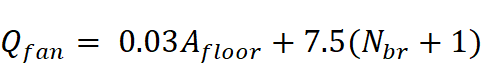
Where:
2)
The required ventilation rate may also be found using Table 4-17. This table allows users to find the required ventilation rate directly if they know the floor area and number of bedrooms.
|
Floor Area (ft2) |
Number of Bedrooms | ||||
|
1 |
2 |
3 |
4 |
≥5 | |
|
<500 |
30 |
40 |
45 |
55 |
60 |
|
500-1000 |
45 |
55 |
60 |
70 |
75 |
|
1001-1500 |
60 |
70 |
75 |
85 |
90 |
|
1501-2000 |
75 |
85 |
90 |
100 |
105 |
|
2001-2500 |
90 |
100 |
105 |
115 |
120 |
|
2501-3000 |
105 |
115 |
120 |
130 |
135 |
|
3001-3500 |
120 |
130 |
135 |
145 |
150 |
|
>3501 |
135 |
145 |
150 |
160 |
165 |
From ASHRAE 62.2, Table 8.2.1a
Corridors and other common areas within conditioned space must be provided a ventilation rate of 0.06 cfm per ft2 of floor area. This required ventilation rate for common areas can be calculated using Equation 4-10:
Equation 4-10
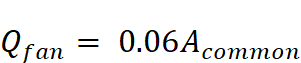
Where:
 2)
2)
Nonresidential spaces in mixed-use buildings must meet the requirements of ASHRAE 62.1, Ventilation for Acceptable Indoor Air Quality.
Common parking garages adjoining occupiable spaces, except parking garages with at least two walls that are at least 5 percent open to the outside, must be provided with exhaust ventilation at a rate given by Equation 4-11:
Equation 4-11
Where:
 2)
2)
This ventilation rate is much higher per ft2 of floor area than most ventilation requirements due to vehicle emission concerns.
4.6.8.2 Other Requirements
From ASHRAE 62.2
Section 8.4 Other Requirements
Section 8.4.1- Transfer Air Measures shall be taken to minimize air movement across envelope components separating dwelling units, including sealing penetrations in the common walls, ceilings, and floors of each unit and by sealing vertical chases adjacent to the units. All doors between dwelling units and common hallways shall be gasketed or made substantially airtight.
8.4.1.1 Compliance. One method for demonstrating compliance with 8.4.1 shall be to verify a leakage rate below a maximum of 0.2 cfm per ft2 of the dwelling unit envelope area (i.e., the sum of the area of the walls between dwelling units, exterior walls, ceiling and floor) at a test pressure of 50 Pa by a blower door test conducted in accordance with either ANSI/ASTM E779-10, Standard Test Method for Determining Air Leakage Rate by Fan Pressurization, or ANSI/ASTM E1827, Standard Test Methods for Determining Airtightness of Buildings Using an Orifice Blower Door. The test shall be conducted with the dwelling unit as if it were exposed to outdoor air on all sides, top, and bottom by opening doors and windows of adjacent dwelling units.
ASHRAE Standard 62.2 requires that measures be taken to minimize air movement across envelope components separating dwelling units from adjacent dwelling units and nearby spaces outside the occupiable space of the dwelling unit. This should include sealing all penetrations in envelope components (for example, light fixtures in roofs, outlets in walls, and base boards around the edge of floors) and sealing vertical chases adjacent to units. Pipe and electrical penetrations are also examples of envelope component penetrations that require sealing. The measures must apply to adjacent units both above and below, as well as side by side.
All doors between dwelling units and common areas must be gasketed or made substantially airtight.
The Energy Standards do not require HERS verification of multifamily envelope leakage rates. The builder or installer must implement measures that meet the ASHRAE 62.2 Section 8.4.1 transfer air requirements. The enforcement agency is responsible for determining compliance, thus may specify inspection criteria or other methods such as the diagnostic method detailed in ASHRAE 62.2 Section 8.4.1.1.
From ASHRAE 62.2
Section 8.5 Air Moving Equipment.
Section 8.5.1 - Exhaust Ducts.
Exhaust fans in separate dwelling units shall not share a common exhaust duct. Exhaust inlets from more than one dwelling unit may be served by a single exhaust fan downstream of all the exhaust inlets if the fan is designated and intended to run continuously or if each inlet is equipped with a back-draft damper to prevent cross-contamination when the fan is not running.
8.5.2 Supply Ducts. Supply outlets to more than one dwelling unit may be served by a single fan upstream of all the supply outlets if the fan is designed and intended to run continuously or if each supply outlet is equipped with a back-draft damper to prevent cross-contamination when the fan is not running.
Exhaust fans in separate dwelling units cannot share a common exhaust duct. Exhaust inlets from more than one dwelling unit may be served by a single exhaust fan downstream of all the exhaust inlets if the fan is designed and intended to run continuously or if each inlet is equipped with a backdraft damper to prevent cross-contamination when the fan is not running.
Supply outlets to more than one dwelling unit may be served by a single fan upstream of all the supply outlets if the fan is designed and intended to run continuously or if each supply outlet is equipped with a backdraft damper to prevent cross-contamination when the fan is not running.