5 APPENDIX B – WATER
HEATING CALCULATION METHOD
B1. Purpose and
Scope
This appendix
documents the methods and assumptions used for calculating the hourly energy use
for residential water heating systems for both the proposed design and the
standard design. The hourly fuel and electricity energy use for water heating
will be combined with hourly space heating and cooling energy use to come up
with the hourly total fuel and electricity energy use to be factored by the
hourly TDV energy multiplier. The calculation procedure applies to low-rise
single family, low-rise multi-family, and high-rise residential.
When buildings
have multiple water heaters, the hourly total water heating energy use is the
hourly water heating energy use summed over all water heating systems, all water
heaters, and all dwelling units being modeled.
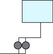
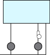
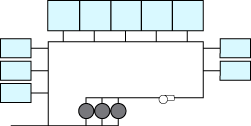
The following
diagrams illustrate the domestic hot water (DHW) system types recognized by the
compliance software.
|
1 |
One distribution system
with one or multiple water heaters serving a single dwelling unit. The
system might include recirculation loops within the dwelling
unit. |

|
|
2 |
Two water heaters with
independent distribution systems serving a single dwelling unit. One or
more of the distribution systems may include a recirculation loop within
the dwelling unit. |

|
|
3 |
One distribution system
without recirculation loop and with one or multiple water heaters serving
multiple dwelling units. |

|
|
4 |
One distribution system
with one or multiple recirculation loops and with one or multiple water
heaters serving multiple dwelling units. |

|
B2. Water
Heating Systems
Water heating distribution systems may serve more than
one dwelling unit and may have more than one water heating appliance. The energy
used by a water heating system is calculated as the sum of the energy used by
each individual water heater in the system. Energy used for the whole building
is calculated as the sum of the energy used by each of the water heating
systems. To delineate different water heating elements several indices are
used.
i
Used to describe an individual dwelling unit. For instance, CFAi would be the
conditioned floor area of the ith
dwelling unit. Nunit is the total number of dwelling units.
j
Used to refer to the number of water heaters in a system. NWH is the total
number of water heaters.
k
Used to refer to a water heating system or distribution system. A building can
have more than one system and each system can have more than one water heater.
l
Used to refer to the lth
unfired- or indirectly-fired storage tank in the kth system. NLk is the total number
of unfired- or indirectly-fired storage tanks in the kth system. Temperature buffering
tanks with electric heating (e.g., minitanks) shall not
to be treated as
unfired or indirectly-fired storage tanks.
|
Symbol |
Definition |
Notes |
|
CFA |
Conditioned floor area,
ft2 |
|
|
NFloor |
Number of floors in
building |
|
|
Nunit |
Number of units in
building |
|
|
NK |
Number of water heating
systems |
|
|
NWHk |
Number of water heaters
in kth system |
|
|
NLoopk |
Number of recirculation
loops in kth system (multi- unit dwellings only) |
|
|
CFAi |
Conditioned floor area of
ith dwelling unit |
|
|
CFAUk |
Average unit conditioned
floor area served by kth system, ft2 |
|
B3. Hot Water Consumption
The schedule of
hot water use that drives energy calculations is derived from measured data as
described in (Kruis, 2016). That analysis produced 365 day sets of fixture water
draw events for dwelling units having a range of number of bedrooms. The draws
are defined in the files DHWDUSF.TXT (for single family) and DHWDUMF.TXT (for
multifamily) that ship with CBECC- Res. Each draw is characterized by a start
time, duration, flow rate, and end use. The flow rates given are the total flow
at the point of use (fixture or appliance). This detailed representation allows
derivation of draw patterns at 1 minute intervals as is required for realistic
simulation of heat pump water heaters.
The fixture flow
events are converted to water heater (hot water) draws by 1) accounting for
mixing at the point of use and 2) accounting for waste, distribution heat
losses, and solar savings --
VSk
=
VFk
×
fhot
×
fwh
Equation 1
Where
VSk
=
Hot water draw at the kth water heating
system’s delivery point (gal)
VFk
=
Mixed water draw at an appliance or fixture (gal) served by the kth water heating system, as specified by
input schedule
 fhot,
fwh
=
End-use-specific factors from the following –
|
End
use |
fhot |
fwh |
|
Shower |
105
− Tinlet Ts − Tinlet |
WFk
× max(0,
DLMk
− SSFk
) |
|
Bath |
|
Faucet |
0.50 |
1
−
SSFk |
|
Clothes washer |
0.22 |
|
Dish washer |
1 |
Ts
=
Hot water supply temperature (ºF). Assumed to be 115 °F. Tinlet
=
Cold water inlet temperature (ºF) as defined in Section B3.3. WFk
= Hot water waste factor.
•
WFk = 0.9 for within-dwelling-unit
pumped circulation systems (see Table B-1).
•
WFk = 1.0 otherwise
DLMk
=
Distribution loss multiplier (unitless), see Equation 5.
SSFk
=
Hourly solar savings fraction (unitless) for the kth water heating
system, which is the fraction of the total water heating
load that is provided by solar hot water
heating.
The annual average
value for SSF is provided from the results generated by the CEC approved
calculations approaches for the OG-100 and OG-300 test procedure. A CEC approved
method shall be used to convert the annual average value for SSF to hourly
SSFk values for use in compliance
calculations.
The individual water
heater draws are combined to derive the overall demand for hot water.
For each hour of
the simulation, all water heater draws are allocated to 1 minute bins using each
draw’s starting time and duration. This yields a set of 60 VSk,t values for each hour that are used as input
to the detailed heat pump water heating model (HPWH) as discussed in section B7.7.
For
hourly
efficiency-based models used for some water heater types, the minute-by-minute
values are summed to give an hourly hot water requirement --
60
GPHk =
∑VSk ,t
t
=1
Equation 2
In cases where
multiple dwelling units are served by a common water heating system, the
dwelling unit draws are summed.
In cases where
there are multiple water heating systems within a dwelling unit, the draws are
divided equally among the systems. For minute-by-minute draws (for HPWH models),
this allocation is accomplished by assigning draws to systems in rotation within
each end use. This ensures that some peak draw events get assigned to each
system. Since heat pump water heater performance is non-linear with load (due to
activation of resistance backup), allocation of entire events to systems is
essential. Note that realistic assignment of draws to specific systems requires
information about the plumbing layout of the residence and capturing that is
deemed to impose an unacceptable user input burden.
B4. Hourly Adjusted Recovery
Load
The hourly adjusted
recovery load for the kth water heating system is calculated as follows:
NLk
HARLk =
HSEUk +
HRDLk +∑HJLl
1
Equation 3
where
HSEUk
=
Hourly standard end use at all use points (Btu), see Equation 4.
HRDLk
=
Hourly recirculation distribution loss (Btu), see Equation
11.
HDRLk is non-zero only for multi-family central water
heating systems.
NLk
=
Number of unfired or indirectly-fired storage tanks in the kth system
HJLl
=
Tank surface losses of
the lth unfired tank of
the kth system (Btu), see Equation 40.
quation 4
calculates the hourly standard end use (HSEU). The heat content of the water
delivered at the fixture is the draw volume in gallons (GPH) times the
temperature rise ∆T (difference between the cold water inlet temperature and the
hot water supply temperature) times the heat required to elevate a gallon of
water 1 ºF (the 8.345 constant).
HSEUk =
8.345 ×
GPHk ×
(Ts −
Tinlet )
Equation 4
where
HSEUk
=
Hourly standard end use (Btu).
GPHk
=
Hourly hot water consumption (gallons) from Equation 2
Equation 5
calculates the distribution loss multiplier (DLM) which combines two terms:
the standard distribution loss multiplier (SDLM), which depends on the floor
area of the dwelling unit and the distribution system multiplier (DSM) listed in
Table
B-1.
|
DLM
k
= 1
+
(SDLM
k
−
1)× DSM
k |
Equation
5 |
where
DLMk
=
Distribution loss multiplier
(unitless)
SDLMk
=
Standard distribution loss multiplier (unitless), see Equation 6. DSMk
=
Distribution system multiplier (unitless), see Section 3.2.
Several
relationships below depend on CFAk, the
floor area served
Equation 6
calculates the standard distribution loss multiplier (SDLM) based on
dwelling unit floor area. Note that in Equation 6, that floor area is
capped at 2500 ft2
-- without that limit, Equation 6 produces unrealistic SDLMk values for large floor areas.
|
SDLMk
=
1.004
− 0.0000000231× min
(2500,
CFAUk
)
× min
(2500,
CFAUk
) |
Equation
6 |
where
SDLMk=
Standard distribution loss multiplier
(unitless).
CFAUk= Dwelling unit conditioned floor area (ft2)
served by the kth system, calculated using methods specified in Equation
7.
|
Single dwelling
unit,
CFAUk
= CFA
/ NK
For multiple dwelling units
served by a central system:
∑all
units
served
by
system
k
CFAi
CFAUk =
Nunit
k
Alternatively, if the
system-to-unit relationships not known:
∑all
units
served
by
any
central
system
CFAi
CFAUk
=
Number of
units served by any central system |
Equation
7
Method WH-CFAU |

 Note: “Method” designations are invariant
tags that facilitate cross-references from comments in implementation code.
When a water heating
system has more than one water heater, the total system load is assumed to be
shared equally by each water heater, as shown in Equation 8.
|
HARL
= HARLk
j
NWHk |
Equation
8 |
 where
where
HARLj
=
Hourly adjusted recovery load for
the jth water heater of
the kth system (Btu). HARLk Hourly adjusted total recovery
load for the kth
system (Btu)
NWHk
=
The number of water heaters in the kth system.


