There are four energy-saving measures associated with commercial kitchen ventilation. These four prescriptive measures address:
1. Direct replacement of exhaust air limitations.
2. Type I exhaust hood airflow limitations.
3. Makeup and transfer air requirements.
4. Commercial kitchen system efficiency options.
There are no mandatory measures specific to commercial kitchens. Installed appliances and equipment must meet the mandatory requirements of §110.1 and §110.2, respectively.
10.3.3.1 Kitchen Exhaust Systems
This section addresses kitchen exhaust systems. There are two requirements for kitchen exhaust:
1. A limitation on use of short-circuit hoods §140.9(b)1A
2. Maximum exhaust ratings for Type I kitchen hoods §140.9(b)1B
A. Limitation of Short-Circuit Hoods
Short-circuit hoods are limited to ≤10% replacement air as a percentage of hood exhaust airflow rate. The reasons for this include the following:
Studies by Pacific Gas and Electric (PG&E), American Gas Association (AGA) and the Energy Commission have shown that in short-circuit hoods, direct supply greater than 10% of hood exhaust significantly reduces capture and containment. This reduces the extraction of cooking heat and smoke from the kitchen, forcing facilities to increase the hood exhaust rate. This reduction results in higher consumption of energy and conditioned makeup air.
Figure 10-2: Short-Circuit Hood

B. Maximum Exhaust Ratings for Type I Kitchen Hoods
The Energy Standards also limit the amount of exhaust for Type I kitchen hoods based on Table 140.9-A (Table 10-1 below), when the total exhaust airflow for Type I and II hoods are greater than 5,000 cfm. Similar to the description regarding short-circuit hoods, excessive exhaust rates for Type I kitchen hoods increases energy consumption and increases energy use for conditioning of the makeup air.
There are two exceptions for this requirement:
1. Exception 1 to §140.9(b)1B, where ≥75% of the total Type I and II exhaust makeup air is transfer air that would otherwise have been exhausted. This exception could be used when you have a large dining area adjacent to the kitchen, which would be exhausting air for ventilation even if the hoods were not running. The exception is satisfied if the air that would otherwise have been exhausted from the dining area (to meet ventilation requirements), is greater than 75 percent of the hood exhaust rate, and is transferred to the kitchen for use as hood makeup air.
2. Exception 2 to §140.9(b)1B: Existing hoods that are not being replaced as part of an addition or alteration.
The values in Table 140.9-A are based on the type of hood (left column) and the rating of the equipment that it serves (light-duty through extra-heavy-duty). The values in this table are typically less than the minimum airflow rates for hoods that are not Underwriter Laboratories (UL) specification listed products. These values are supported by ASHRAE research for use with UL-listed hoods. (For more detail see ASHRAE research project report RP-1202.) To comply with this requirement, the facility will likely have to use listed hoods. The threshold of 5,000 cfm of total exhaust was included in the Energy Standards to exempt small restaurants.
The definitions for the types of hoods and the duty of cooking equipment are provided in ASHRAE Standard 154-2011.
Example 6-6 Mounting Height from the Property Line
Question
How are the BUG rating of a luminaire determined by mounting height from the property line?
Answer
If the luminaire is mounted more than 2 mounting heights away from the property line, then there is no limit on the backlight rating. Otherwise, for locations less than 2 mounting height away, the luminaire must meet backlight ratings listed in Table 5.106.8 (N).
For instance, a 6,600-lumen parking lot luminaire rated with a B2-U0-G1 BUG rating is installed on a 20-foot pole. If this luminaire is located 2 mounting heights (40 feet) away from the closest property line, it is acceptable for use in a lighting zone 2 (LZ2) or higher lighting zone (LZ3 or higher) location.
The luminaire lumen output and BUG ratings can be obtained from the manufacturer or may be calculated from photometric data.
|
Type of Hood |
Medium-Duty Equipment |
Heavy-Duty Equipment |
Extra-Heavy Duty Equipment | |
|
Wall-mounted Canopy |
140 |
210 |
280 |
385 |
|
Single Island |
280 |
350 |
420 |
490 |
|
Double Island |
175 |
210 |
280 |
385 |
|
Eyebrow |
175 |
175 |
Not Allowed |
Not Allowed |
|
Backshelf/Pass-over |
210 |
210 |
280 |
Not Allowed |
Energy Standards Table 140.9-A
10.3.3.2 Kitchen Ventilation
This section covers two requirements:
1. Limitations to the amount of mechanically heated or cooled airflow for kitchen hood makeup air §140.9(b)2A
2. Additional efficiency measures for large kitchens §140.9(b)2B.
For these requirements, it is important to understand the definition of mechanical cooling and mechanical heating, which the Energy Standards define as:
a. Mechanical cooling is lowering the temperature within a space using refrigerant compressors or absorbers, desiccant dehumidifiers, or other systems that require energy from depletable sources to directly condition the space. In nonresidential, high-rise residential, and hotel/motel buildings, cooling of a space by direct or indirect evaporation of water alone is not considered mechanical cooling.
b. Mechanical heating is raising the temperature within a space using electric resistance heaters, fossil-fuel burners, heat pumps, or other systems that require energy from depletable sources to directly condition the space.
Direct and indirect evaporation of water alone is not considered mechanical cooling. Therefore, air cooled by the evaporation of water can be used as kitchen hood makeup air with no restrictions.
A. Limitations to the Amount of Mechanically Heated or Cooled Airflow for Kitchens
This section limits the amount of mechanically cooled or heated airflow to any space with a kitchen hood. The amount of mechanically cooled or heated airflow must not exceed the greater of:
1. The supply flow required to meet the space heating or cooling load.
2. The hood exhaust minus the available transfer air from adjacent spaces.
The supply flow required to meet the space heating or cooling loads can be documented by providing the load calculations.
To calculate the available transfer air:
1. Calculate the minimum outside air (OA) needed for the spaces that are adjacent to the kitchen.
2. From the amount calculated in 1, subtract the amount of air used by exhaust fans in the adjacent spaces. This amount includes toilet exhaust and any hood exhaust in adjacent spaces.
3. From the amount calculated in 2, subtract the amount of air needed for space pressurization. The remaining air is available for transfer to the hoods.
An exception is provided for existing kitchen makeup air units (MAU) that are not being replaced as part of an addition or alternation.
While the requirement to use available transfer air only refers to "adjacent spaces," available transfer air can come from any space in the same building as the kitchen. A kitchen on the ground floor of a large office building, for example, can draw transfer air from the return plenum and the return shaft. The entire minimum OA needed for the building, minus the other exhaust and pressurization needs, is available transfer air. If the return air path connecting the kitchen to the rest of the building is constricted, resulting in high transfer air velocities, then it may be necessary to install a transfer fan to assist the transfer air in making its way to the kitchen. The energy use of a transfer fan is small compared to the extra mechanical heating and cooling energy of an equivalent amount of OA.
Example 10-1
Question
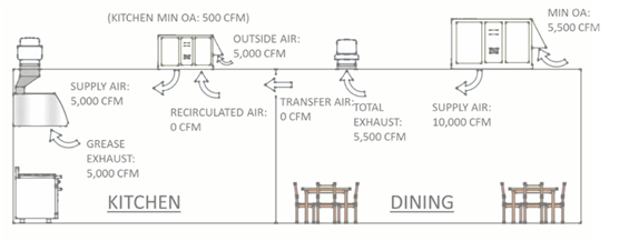
What is the available transfer air for the kitchen makeup in the scenario shown in the following figure?

Answer
5,000 cfm calculated as follows.
The OA supplied to the dining room is 5,500 cfm. From this, subtract 500 cfm for the toilet exhaust and 0 cfm for building pressurization.
5,500 cfm – 500 cfm – 0 cfm = 5,000 cfm
The remaining 5,000 cfm of air is available transfer air.
Example 10-2
Question
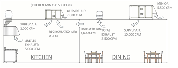
Assuming that this kitchen needs 2,000 cfm of supply air to cool the kitchen with a design supply air temperature of 55°F, would the following design airflow meet the requirements of §140.9(b)2A?

Answer
Yes. This example meets the first provision of §140.9(b)2A. The supply flow required to meet the cooling load is 2,000 cfm. Thus, up to 2,000 cfm of mechanically conditioned makeup air can be provided to the kitchen. The supply from the MAU, 2,000 cfm, is not as large as the hood exhaust, 5,000 cfm. This means that the remainder of the makeup air, 3,000 cfm, must be transferred from the dining room space.
Although this is allowed under §140.9(b)2Ai, this is not the most efficient way to condition this kitchen, as demonstrated in the next example.
Example 10-3
Question
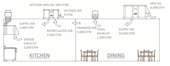
Continuing with the same layout as the previous example, would the following design airflow meet the requirements of §140.9(b)2A?

Answer
Yes. In this example, 100% of the makeup air, 5,000 cfm, is provided by transfer air from the adjacent dining room. The OA on the unit serving the dining room has been increased to 6,000 cfm to serve the ventilation for both the dining room and kitchen. Since the dining room has no sources of undesirable contaminants, we can ventilate the kitchen with the transfer air.
Comparing this image to the previous example you will see that this design is more efficient for the following reasons:
1. The total outside airflow to be conditioned has been reduced from 7,500 cfm in the previous example (2,000 cfm at the MAU and 5,500 cfm at the dining room unit) to 6,000 cfm.
2. The dining room exhaust fan has dropped from 2,500 cfm to 1,000 cfm reducing both fan energy and first cost of the fan.
An even more efficient design would be if the kitchen MAU had a modulating OA damper that allowed it to provide up to 5,000 cfm of outside air directly to the kitchen when OA temperature < kitchen space temperature. When OA temperature > kitchen space temperature, then the OA damper on the MAU is shut, and replacement/ventilation air is transferred from the dining area. This design requires a variable-speed dining room exhaust fan controlled to maintain slight positive pressure in the dining area. This design is the baseline design modeled in the Alternative Calculation Methods (ACM) Reference Manual for performance compliance. The baseline model assumes that transfer air is available from the entire building, not just the adjacent spaces.
Example 10-4
Question
Continuing with the same layout as the previous examples, would the following design airflow meet the requirements of §140.9(b)2A?

Answer
Not if the kitchen is mechanically heated or cooled. Per §140.9(b)2A, the maximum amount of makeup air that can be mechanically heated or cooled cannot exceed the greater of:
1. Per §140.9(b)2Ai: 2,000 cfm, the supply needed to cool the kitchen (from Example 10-2)
2. Per §140.9(b)2Aii: 0 cfm, the amount of hood exhaust (5,000 cfm) minus the available transfer air (5,500 - 500 = 5000 cfm; from Example 10-2).The 5,000 cfm of conditioned makeup air exceeds 2,000 cfm. This example assumes that the required exhaust for the dining space is 500 cfm of bathroom exhaust and the remaining 5,000 cfm of dining outdoor air is available for transfer to the kitchen.
B. Additional Efficiency Measures for Large Kitchens
For kitchens or dining facilities that have more than 5,000 cfm of Type I and II hood exhaust, the mechanical system must meet one of the following requirements:
1. At least 50% of all replacement air is transfer air that would have been exhausted.
2. Demand ventilation control on at least 75% of the exhaust air.
3. The listed energy recovery devices have a sensible heat recovery effectiveness ≥40% on ≥50% of the total exhaust flow.
4. Seventy-five percent or more of the makeup air volume is:
a. Unheated or heated to no more than 60°F.
b. Uncooled or cooled without the use of mechanical cooling.
Exception to 140.9(b)2B: Existing hoods not being replaced as part of an addition or alteration.
Transfer Air: The concept of transfer air was addressed in the discussion of §140.9(b)2A above.
Demand Ventilation Control: Per §140.9(b)2Bii, demand ventilation controls must have all the following characteristics:
a. Include controls necessary to modulate airflow in response to appliance operation and to maintain full capture and containment of smoke, effluent, and combustion products during cooking and idle.
b. Include failsafe controls that result in full flow upon cooking sensor failure.
c. Include an adjustable timed override to allow occupants the ability to temporarily override the system to full flow.
d. Be capable of reducing exhaust and replacement air system airflow rates to the larger of:
1. 50% of the total design exhaust and replacement air system airflow rates.
2. The ventilation rate required in §120.1.
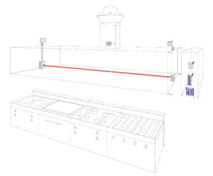
There are several off-the-shelf technologies that use smoke detectors that can comply with all these requirements.
Figure 10-3: Demand Control Ventilation Using a Beam Smoke Detector

Energy Recovery: Energy recovery is provided using air to air heat exchangers between the unit providing makeup air and the hood exhaust. This option is most effective for extreme climates (either hot or cold) and less commonly used in the mild climates of California.
Tempered Air with Evaporative Cooling: The final option is to control the heating (if there is heating) to a space by setting the temperature set point to 60°F and to use evaporative (non-compressor) cooling or no cooling at all for 75% of the makeup air.
10.3.3.3 Kitchen Exhaust Acceptance
Acceptance tests for these measures are detailed in NA7.11. See Chapter 13 of this manual.
10.3.3.4 Healthcare Facilities
Healthcare facilities are not required to meet 140.9(b).
See above sections for specific applications of these measures to additions and alterations.