§140.9(c) sets the minimum requirements for laboratory and factory exhaust systems. Laboratories have an average annual energy intensity 10-20 times larger than offices when normalized by building area. The primary drivers of laboratory building energy are long operation hours, exhaust fan energy, and makeup air conditioning in addition to typically high internal loads.
To help reduce laboratory and factory energy use, there are four categories of exhaust energy saving measures:
•Exhaust and makeup air reduction
•Reduction of conditioned makeup air
•Exhaust fan power reduction
•Fume hood automated sash closures
Laboratories in healthcare facilities are not required to meet the requirements of §140.9(c).
There are no mandatory measures specific to laboratory exhaust, but the equipment efficiencies in §110.1 and §110.2 apply.
Summary of measures contained in this section:
•Airflow Reduction Requirements - §140.9(c)1
•Exhaust System Transfer Air - §140.9(c)2
•Fan System Power Consumption - §140.9(c)3
•Fume Hood Automatic Sash Closure - §140.9(c)4
10.7.3.1 Airflow Reduction Requirements
§140.9(c)1 requires that all laboratory exhaust with minimum circulation rates of 10 air changes per hour (ACH) or lower shall be designed for variable-volume control on the supply, fume exhaust, and general exhaust. This requirement will enable the system to reduce zone exhaust and makeup airflow rates to the minimum allowed for ventilation or to maintain the required differential pressure for the zone.
An exception is provided for laboratory exhaust systems where constant volume is required by code, the authority having jurisdiction (AHJ), or the facility environmental health and safety (EH&S) division [Exception 1 to §140.9(c)1]. Examples include hoods using perchloric acid, hoods with radio isotopes, and exhaust systems conveying dust or vapors that need a minimum velocity for containment.
A second exception is provided for new zones added to an existing constant volume exhaust system [Exception 2 to §140.9(c)1].
The energy and demand savings depend strongly characteristics of the facility, including:
1. Ratio of lab to non-lab space.
2. Minimum airflow required by code or the facility EH&S department. These range from 4 to 18 ACH or higher.
3. Climate zone.
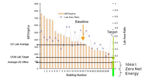
Figure 10-38 shows benchmarking data from Labs 21 for lab buildings in the San Francisco Bay Area. The total energy use intensity in kBtu/gsf/yr is shown on the left axis. The 26 labs are arranged from highest to lowest normalized energy use. The right axis is the "Lab Area Ratio," the ratio of lab area to total building area. There are three reference lines on this graph: the University of California campus wide average laboratory building end-use intensity, the University of California, Merced, campus goal for its laboratories; and the average national energy end use for office buildings.
Figure 10-38: Laboratory Benchmarking From Labs 21 for San Francisco Bay Area
Using the criteria for cost-effectiveness in the Energy Standards and very conservative estimates of the first costs (using costs from VAV retrofits not new construction), this measure was shown to be cost-effective in all California climate zones up to 14 ACH of minimum ventilation
Using off-the-shelf variable air volume (VAV) controls can greatly reduce the energy use in laboratory buildings. The Energy Standards require VAV controls on all zones not required to be constant volume by the AHJ, facility EH&S department, or other applicable health and safety codes. Furthermore, ANSI/AIHA Z9.5 and NFPA 45 allow lower minimum airflows for many hoods, which increases the savings from VAV design.
Figure 10-39 below shows the zone components for a VAV laboratory. There are three zone valves shown in this image: one each on the supply air to the zone, the fume hood (if one exists), and the general exhaust valve (GEX), if one is needed. These zone valves can be venturi type valves as shown in this image or standard dampers like those used for VAV boxes in offices. The dampers or venturi valves must be designed to resist corrosion and damage from the exhaust. When used, the hood valve is controlled to automatically maintain the design sash face velocity as the hood sash is opened or closed. The role of the supply valve is to maintain space pressurization by tracking the sum of the hood and general exhausts in the space. The supply valves are typically provided with reheat coils to maintain space comfort for heating. The GEX is typically used to control the cooling, on a call for cooling it opens, and the supply valve, in turn, opens to maintain space pressure. In some systems the supply modulates like a typical VAV box in response to the thermostat, and the GEX modulates to maintain space pressure.
All three valves are made to control either variable volume or constant volume depending on the application. A hood might for instance be required to maintain constant volume for dilution. If this is the case, a constant volume bypass hood should be employed. Even with a constant volume hood, you will need a pressure independent hood valve if the attached exhaust also serves variable-volume zones. The same rule applies for constant volume supply or general exhaust. If any zone on a supply or exhaust duct is variable volume, all zone ducts on it must have pressure independent controls.
Figure 10-39: Zone Components For a VAV Lab

The fume exhaust is generally blown out of a stack. The design of the stack and the velocity of the discharge are selected to disperse all contaminants so that they are sufficiently dilute by the time they are near any occupants. For contaminants like radio isotopes for which there is no acceptable level of dilution, the exhaust system typically has some form of filtration that captures the particles of concern. On general lab exhaust, there is typically an inlet bypass damper on the exhaust fan that modulates to keep a constant volume of exhaust moving at the stacks. Using multiple stacks in parallel, you can stage off stacks and fans to save more energy.
10.7.3.2 Exhaust System Transfer Air
This section limits the amount of conditioned air supplied to a space with mechanical exhaust. The benefit of this requirement is to take advantage of available transfer air. By doing so, the amount of air that needs to be conditioned is limited, thus saving energy. Conditioned supply air is limited to the greater of:
1. The supply flow required to meet the space heating or cooling load.
2. The ventilation rate required by the AHJ, facility EH&S department, or by §120.1(c)3.
3. The mechanical exhaust flow minus the available transfer air.
The supply flow required to meet the space heating or cooling loads can be documented by providing load calculations.
Available transfer air can be from adjacent conditioned spaces or return air plenums that are on the same floor, same smoke or fire compartment, and within 15 feet. To calculate the available transfer air:
1. Calculate the minimum outside air required by adjacent spaces.
2. From 1, subtract the amount of air required by adjacent space exhaust.
3. From 2, subtract the amount of air required to maintain pressurization of adjacent spaces. This is your available transfer air.
Exceptions are provided for:
1. Laboratories classified as biosafety level 3 or higher.
2. Vivarium spaces.
3. Spaces required to maintain positive pressure differential relative to adjacent spaces.
4. Spaces that require a negative pressure relationship and the demand for transfer air may exceed the available transfer airflow rate.
10.7.3.3 Fan System Power Consumption
Newly installed laboratory and factory exhaust systems greater than 10,000 CFM have three prescriptive pathways to show compliance with this section. Regardless of the path chosen, all exhaust systems must meet the discharge requirements of ANSI Z9.5.
ANSI Z9.5-2012 Discharge Requirements:
Section 5.4 and Appendix 3 of ANSI Z9.5, Laboratory Ventilation, describe standards for laboratory exhaust system design including the discharge requirements cited by this section of the Energy Standards.
Exhaust Fan System Power Consumption:
As described in greater detail for the previous VAV section, one of the major drivers of laboratory and factory energy is fan power. To reduce this demand, three prescriptive pathways have been added for the 2019 code cycle. The first and simplest pathway is an exhaust system power limit of 0.65 or 0.85 W/cfm depending on system design. The other two options do not limit exhaust system power, but instead require exhaust volume flow rate control based on either local wind conditions or exhaust chemical concentration.
Option 1: Exhaust System Efficacy:
•Systems without air treatment devices are limited to 0.65 W/cfm of exhaust air.
•Systems with air filtration, scrubbers, or other air treatment devices are limited to 0.85 W/cfm of exhaust air.
•An exception is provided for systems with code required air treatment devices that cause static pressure drop greater than 1 inch of water. For example, a local jurisdiction which has an ordinance for high exhaust filtration, which causes high filter static pressure, due to smell or other exhaust considerations.
Option 2: Wind-Based Exhaust Volume Flow Rate Control:
This compliance path saves fan energy by reducing exhaust stack airflow when local wind conditions permit. The Energy Standards, ANSI Z9.5, and other best engineering practices dictate several necessary components to this type of system:
1. Anemometer Sensors:
a. Two anemometer sensors must be used to enable sensor fault detection.
b. Installation location must exhibit similar wind speed and direction to the free stream air above the exhaust stacks.
c. Sensors must be located high enough to be above the wake region created by nearby structures.
d. Sensors must be factory calibrated.
e. Sensors must be certified by the manufacturer to an accuracy of ± 40 feet per minute (fpm), ± 5.0 degrees, and to require calibration no more than every five years.
2. Dispersion Modeling:
a. Wind dispersion analysis must be used to create a look-up table for exhaust volume flow rate versus wind speed/direction.
b. Look-up table must contain at least eight wind speeds and eight wind directions to define the safe exhaust volume flow rate.
c. Exhaust volume flow rate must be based on maintaining downwind chemical concentrations below health and odor limits as defined by the 2018 American Conference of Governmental Industrial Hygienists, Threshold Limit Values and Biological Indices, or more stringent, local, state, and federal limits if applicable.
3. Sensor Fault Management:
a. Minimum sensor failure thresholds:
•If any sensor has not been calibrated within the associated calibration period.
•Any sensor that is greater than ±30% of the four-hour average reading for all sensors.
b. Upon sensor failure, the system must revert to a safe exhaust volume flow rate based on worst-case wind conditions. Furthermore, the system must report the fault to an Energy Management Control System or other application which notifies a remote system provider.
4. Certification of requirements listed in NA7.16 for wind speed/direction control
Option 3: Contaminant Concentration-Based Exhaust Volume Flow Rate Control:
This compliance path saves fan energy by reducing exhaust airflow when the exhaust contaminant concentration is low enough to maintain safe downwind concentrations. The Energy Standards and best engineering practices dictate several necessary components to this type of system:
1. Chemical Concentration Sensors:
o Two contaminant concentration sensors must be used in each exhaust plenum to enable sensor fault detection.
o Sensors must be photo ionization detectors.
o Sensors must be factory calibrated.
o Sensors must be certified by the manufacture to an accuracy of ± 5% and require calibration no more than every six months.
2. Dispersion Modeling:
o Wind dispersion analysis must be used to determine contaminant-event thresholds (contaminant concentration levels), which control when the exhaust volume flow rate can be turned down during normally occupied hours.
o Exhaust volume flow rate must be based on maintaining downwind chemical concentrations below health and odor limits as defined by the 2018 American Conference of Governmental Industrial Hygienists, Threshold Limit Values and Biological Indices, or more stringent, local, state, and federal limits, if applicable.
3. Sensor Fault Management:
o Minimum sensor failure thresholds:
•If any sensor has not been calibrated within the associated calibration period.
•Any sensor that is greater than ±30% of the four-hour average reading for all sensors.
o Upon sensor failure, the system must revert to a safe exhaust volume flow rate based on worst-case wind conditions. Moreover, the system must report the fault to an energy management control system or other application that notifies a remote system provider.
4. Certification of requirements listed in NA7.16 for contaminant control
Example 10-55
Question
A laboratory space has 2,500 ft2 of conditioned floor area, a drop ceiling for plenum space, and ceiling height of 10 feet. The lab has a minimum ventilation rate of 2,500 cfm.
Is this laboratory required to have variable-volume exhaust and makeup air flow to comply with Section 140.9(c)1?
Answer
In the absence of any other code or environmental health & safety requirement for constant speed operation, Section 140.9(c)1 requires that laboratories have variable-volume exhaust and makeup airflow if the minimum ACH is less than or equal to 10. For this laboratory space, ACH is equal to the following, noting that ACH is calculated for laboratory conditioned space not including plenum volume:
ACH = 2,500 cfm x 60 min / hr / (2,500 ft2 x 10 ft) = 6 ACH
Thus, if there is no conflicting code or safety requirement for constant volume operation, this space requires a variable-volume HVAC system.
Example 10-56
Question
A variable-volume supply fan and a variable-volume exhaust fan serving a lab system has a fan system design supply airflow and design exhaust airflow of 8,000 cfm. The system consists of one supply fan operating at an input power of 4.0 bhp and one exhaust fan operating at an input power of 8.0 bhp. The exhaust system uses a 0.6 in. pressure drop filtration device, airflow control devices, and serves fume hoods.
Does this fan system comply with the fan power requirements in Title 24?
Answer
For laboratory exhaust systems with total flow rates less than or equal to 10,000 cfm, the total fan energy of the space conditioning system and the laboratory exhaust system must comply with Section 140.4(c). First, the design fan power must be calculated in bhp, as shown below:
Design Fan Power = 5.0 bhp + 8.0 bhp = 13.0 bhp
Then, the fan power limit in section 140.4(c) is determined. From Table 140.4-A, the allowable system input power for the system is:
bhp = CFMs × 0.0013 + A = 8,000 × 0.0013 + A = 10.4 + A
where A accounts for pressure drop adjustments.
From Table 140.4-B, the pressure drop adjustment for the exhaust flow control device (FC) is 0.5 in. of water, the pressure drop adjustment for fully ducted exhaust systems (DE) is 0.5 in. of water, and the pressure drop adjustment for the fume hoods (FH) is 0.35 in. of water. The pressure drop adjustment for fully ducted exhaust systems is included because laboratory exhaust systems are required under Title 8 to be fully ducted. An additional pressure drop adjustment is allowed to be equal to the design pressure drop of an exhaust filtration device (FD) which for this design is 0.6 in. of water column. The airflow through all these devices is 8,000 cfm, so the additional input power that is allowed is 3.8 bhp, as calculated below.
A = [CFMFC × PDFC + CFMDE × PDDE + CFMFH × PDFH + CFMFD × PDFD] / 4,131
A = [8,000 × 0.5 + 8,000 × 0.5 + 8,000 x 0.35 + 8,000 x 0.6] / 4131 = 3.8 bhp
The total allowed input power is 10.4 bhp plus 3.8 bhp, or 14.2 bhp. Because the design fan power of 13.0 bhp is less than 14.2 bhp, the system does comply using the procedure in section 140.4(c). If the system did not comply, one could evaluate several methods of dropping the design brake horsepower such as: lowering pressure drop though the system by increasing duct size or selecting low pressure drop valves or low pressure drop duct fittings. Alternatively, brake horsepower can be dropped by selecting a fan with higher fan efficiency at the design point.
Example 10-57
Question
A variable-volume supply fan and a variable-volume exhaust fan serving a lab system has a fan system design supply airflow and design exhaust airflow of 12,000 cfm. The system consists of one supply fan operating at an input power of 10.0 bhp served by a nominal 15 hp motor and one exhaust fan operating at an input brake horsepower of 18.0 bhp served by a nominal 25 hp motor, which at design conditions draws 14.4 kW. The exhaust system uses a 0.6 in. pressure drop filtration device and airflow control devices and serves fume hoods.
Does this fan system comply with the fan power requirements in Title 24?
Answer
For laboratory exhaust systems with total flow rates greater than 10,000 cfm, the fan energy of the space conditioning system is regulated by the requirements of Section 140.4(c) and the fan energy of the laboratory exhaust system is regulated by Section 140.9(c).
For laboratory exhaust systems with total flow rates greater than 10,000 cfm, the fan energy of the space conditioning system is regulated by the requirements of Section 140.4(c) and does NOT include the design exhaust fan power or the pressure drop adjustment credits for:
– Exhaust systems required by code or accreditation standards to be fully ducted.
– Exhaust airflow control devices.
– Exhaust filters, scrubbers, or other exhaust treatment.
– Exhaust systems serving fume hoods.
– Biosafety cabinets.
The fan power limit in Section 140.4(c) is determined. From Table 140.4-A, the allowable system input power for the system can be calculated for either the design motor horsepower for the fan or the brake horsepower supplied to the fan.
For the motor horsepower approach for a variable-volume system, with maximum design airflow rate, cfms, of 12,000 cfm, the nominal horsepower shall be no greater than:
hp < cfms x 0.0015 = 12,000 x 0.0015 = 18 hp
The supply fan had a nominal horsepower of 15 hp. The space conditioning system passes using this approach.
For the fan brake horsepower approach in Section 140.4(c), the allowable system input power for the space conditioning system is:
bhp = CFMs × 0.0013 + A
where A accounts for pressure drop adjustments.
In this case, there are no fan pressure adjustments as all the exhaust system and fume hood credits are accounted for in the allowances to Section 140.9(c)3.
Allowable fan brake horsepower = CFMs × 0.0013 = 12,000 x 0.0013 = 15.6 bhp.
The supply fan had a design brake horsepower of 10.0 bhp, and since this design is less than 15.6 bhp, the space conditioning system passes using this approach.
The second half of this calculation is to determine whether the fan power of the laboratory exhaust systems complies with the requirements in Section 140.9(c)3. As given from the design documents, the exhaust fan draws 14.4 kW during design conditions while moving 12,000 cfm of air. The design fan watts per cfm is:
Design Exhaust Fan W/CFM = 14.4 kW x 1,000 W/kW / 12,000 CFM = 1.2 W/CFM
As described in Section 140.9(c)3B, an exhaust system with an air filtration device will have a maximum allowable exhaust fan power of 0.85 W/CFM. Therefore, the maximum allowable exhaust fan power for this system is 0.85 W/CFM. This is less than the fan system input power of 1.2 W/CFM. Therefore, the system does not comply with the fan power of Section 140.9(c)3B. The designer could redesign the system for lower design watts per cfm by increasing the height of the stack or alternatively design the system to vary the flow rate from the exhaust stack in response to wind speed in accordance with Section 140.9(c)3C or vary the flow rate from the exhaust stack in response to measured contaminant concentration in the exhaust plenum in accordance with Section 140.9(c)3D.
10.7.3.4 Fume Hood Automatic Sash Closure
Fume hood intense laboratories with VAV HVAC systems and vertical fume hood sashes are prescriptively required to install automatic sash closure systems. This measure saves energy by reducing laboratory exhaust air and makeup air conditioning. For this measure, fume hood intense means the air change rate of the space is driven by the fume hood exhaust, not minimum ventilation requirements. See Table 10-17 below, which specifies fume hood intensity by linear hood density and minimum ventilation air change rate.
The Energy Standards and best engineering practices dictate several necessary components to this type of system:
1. Zone Presence Sensors:
•Each sash closure system must have a dedicated zone presence sensor that detects people near the fume hood. Sensor should not be triggered by movement in adjacent zones.
2. Sash should automatically close within 5 minutes of sensing no presence within the fume hood zone.
3. Sash closure system safeguards:
a. Sash automatic closing should stop when no more than 10 lbs is detected.
b. Sash should have obstruction sensors that can detect obstructions, including transparent materials such as glassware.
4. Sash closure system must be configurable in a manual open mode.
1. Manual open mode requires user input (push button, pedal, etc.) to open the sash and will not open automatically from presence detection.
2. This mode is important for two reasons:
•Safety: One example is a fume hood that has cross traffic that could cause inadvertent opening in automatic mode. This unnecessarily exposes occupants to dangerous chemicals.
•Energy Savings: In general, a manual open configuration will save the most energy because the hood is only intentionally opened. Automatic opening mode could cause the sash to open unnecessarily, and fume hoods use more energy when fully open.
3. Automatic closing is unaffected by manual open mode
4. The Energy Standards only require the option of manual mode; sashes can still be configured in auto open mode, if preferred.
5. Certification of requirements listed in NA7.17
Fume Hood Intense Laboratories:
The intention of the fume hood intense definition is to only require automatic sash closures for spaces that have ventilation driven by fume hood exhaust, not minimum outdoor air requirements. With regard to this table, linear feet of fume hoods refer to the nominal hood width, not the sash opening width. The following table defines all spaces that qualify as fume hood intense:
|
Occupied Minimum Ventilation ACH |
≤ 4 |
> 4 and ≤ 6 |
> 6 and ≤ 8 |
> 8 and ≤ 10 |
> 10 and ≤ 12 |
> 12 and ≤ 14 |
|
Hood Density (linear feet per 10,000 ft3 of laboratory space) |
≥ 6 |
≥ 8 |
≥ 10 |
≥ 12 |
≥ 14 |
≥ 16 |
Example 10-58
Question
A variable-volume laboratory space has two rooms with 10-foot ceilings, both of which have minimum ventilation rates of 6 ACH. One room has two 6-foot fume hoods and a floor area of 1,000 square feet. The second room has three 6-foot fume hoods and a floor area of 2,500 square feet.
Which fume hoods are required to have automatic sash closing controls, according to Section 140.9(c)4?
Answer
For each space, determine the fume hood density (FHD) as calculated below, noting that hoods of any sash type contribute to the nominal hood length.
FHD = 10,000 ft3 x Total nominal hood length / (lab space volume)
FHD1000 = 10,000 ft3 x 2 x 6 feet / (1,000 ft2 x 10 ft) = 12
FHD2500 = 10,000 ft3 x 3 x 6 feet / (2,500 ft2 x 10 ft) = 7.2
Using the column for minimum ventilation rate of 6 ACH in reference Table 140.9-B, fume hood densities greater than or equal to 8 are fume hood intensive. Since the 1,000 ft2 room is fume hood intensive, any hoods with vertical only sashes in that space are covered by the automatic sash closing controls prescriptive requirement. Since the 2,500 ft2 room is not fume hood intensive, that space is not required to have sash closing controls.
Example 10-59
Question
A building has two laboratory spaces with fume hoods, one with a minimum ventilation rate of 8 ACH and one with a minimum ventilation rate of 12 ACH. Both are designed to have variable-volume HVAC systems even though Section 140.9(c) only requires variable air volume when minimum ACH is 10 or less.
Which fume hoods are required to have automatic sash closing controls, according to Section 140.9(c)4?
Answer
If the spaces are deemed to be fume hood intensive according to Table 140.9-B for the corresponding minimum ACH, they are required to have sash closing controls on any vertical sash hoods. Automatic sash closing controls are required for any vertical-only hoods in fume hood intensive spaces in variable-volume laboratories.
Variable Exhaust and Makeup Airflow
As noted in the previous, section variable volume controls are not required if you are adding zones to an existing constant volume system.
Exhaust System Transfer Air
Additions and alterations must comply with the requirements of this section. For alterations, this means that any additional exhaust and conditioned air resulting from an alteration must comply with this section.
Fan System Power Consumption
All newly installed exhaust systems greater than 10,000 cfm must meet the requirements of this section. Alterations and additions that increase an existing exhaust system’s airflow rate over the 10,000 cfm threshold do not need to meet the requirements.
Fume Hood Automatic Sash Closure
Additions and alterations must meet the requirements of this section. The addition of fume hoods to a space resulting in a density above the values of Table 140.9-B requires compliance with this section for those newly installed fume hoods.