This manual uses the term “unmet load hours” (UMLH) as a criterion for sizing standard design equipment and for other purposes. The concept of unmet load hours applies to thermal zones but is summed for hours whenever any conditioned thermal zone in the building has unmet loads. For a thermal zone, it represents the number of hours during a year when the HVAC system serving the thermal zone is unable to maintain the setpoint temperatures for heating and/or cooling. During periods of unmet loads, the space temperature drifts above the cooling setpoint or below the heating setpoint. A thermal zone is considered to have UMLH if the space is outside the throttling range for heating or cooling. The throttling range is defined in Chapter 5 as the space temperature difference between no cooling and full cooling, or between no heating and full heating. It is assumed that the cooling and heating setpoints are “centered” on the throttling range so that a cooling setpoint of 75°F results in an acceptable temperature band of 74°F to 76°F. The throttling range is fixed at 2°F for simulating both the standard design and proposed design.
An UMLH can occur only during periods when the HVAC system is scheduled to operate. UMLH are accounted for in each zone of the building. No zone in the building should exceed the maximum allowed UMLH.
UMLH can occur because fans, air flows, coils, furnaces, air conditioners, or other equipment are undersized. UMLH can also occur due to user errors, including mismatches between the thermostat setpoint schedules and HVAC operating schedules or from other input errors, for instance, high internal gains or occupant loads. The term, as used in this manual, addresses only equipment that is undersized. It is the responsibility of the user to address other causes of UMLH in the proposed design.
UMLH apply to thermal zones that contain any space type that is normally occupied. Thermal zones that contain only the space types listed below will not have UMLH applied to them:
•Commercial and industrial storage areas
•Corridors, restrooms, stairs, and support areas
•Electrical, mechanical, telephone rooms
•Laundry rooms
•Locker/dressing rooms
•Unoccupied gross floor areas
•Spaces that are not subject to any UMLH checks or restrictions are listed in Appendix 5.4A.
Calculation Procedures
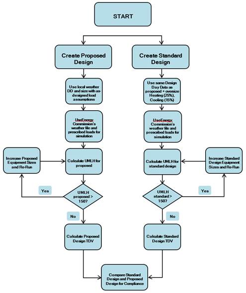
The general calculation procedure is illustrated below in Figure 2. The proposed design TDV energy use is compared to the standard design.
Figure 2: Calculation Process for Title 24 Compliance
Source: NORESCO for California Energy Commission
1. The process begins with a detailed description of the proposed design. Information is provided in enough detail to enable an estimate of annual energy use for a typical weather year. This information includes the building envelope, lighting systems, HVAC systems, water heating systems, and other important energy-using systems. This collection of information is referred to in this manual as building descriptors. Details on the building descriptors are provided in Chapter 5.
2. Before the calculations are performed, some of the building descriptors are modified for the proposed design to incorporate prescribed modeling assumptions. Prescribed modeling assumptions include occupant density, equipment power density, ventilation rates, and water heating loads.
3. The next step is to make a simulation of the proposed design to determine how well the heating and cooling loads are being satisfied. The indicator is UMLH, the number of occupied hours during the year when the space temperature in one or more thermal zones is outside the throttling range. A large number of hours indicate that the equipment is undersized.
4. Test the number of UMLH in the proposed design and proceed only if the hours for each zone in the building are less than or equal to 150 for the year.
5. If the UMLH are greater than 150 for the year, a warning will be presented after the simulation is complete and the compliance report will be watermarked as not usable for compliance. No zone, other than the irregularly occupied space types listed above, may exceed 150 UMLH. If the problem is heating, then the size of the boiler or furnace may need to be increased. If the problem is cooling, then the size of the coils or chillers may need to be increased, or users can add a phantom cooling system by checking a box in the thermal zone “Add Cooling System to Meet Load”. In some cases, adjusting the zone airflows may also solve the UMLH issue. It is up to the designer to adjust equipment sizes as necessary.
6. If the UMLH are fewer than or equal to 150, then the final simulation is performed. If no changes are made in the model, this may be the same simulation in step 3. These calculations produce the results that are compared to the standard design, which is calculated in steps 7 through 16.
7. Create the standard design following the rules in this manual. The standard design has the same floor area, number of floors, and spatial configuration as the proposed design; however, systems and components are modified to be in minimum compliance with the standard design. The HVAC systems for the standard design are established according to rules in this manual and depend on the primary building activity (residential or nonresidential), the floor area, and the number of stories. See Section 5.1
8. Sizing calculations are performed for the standard design and heating equipment is oversized by 25 percent and cooling equipment by 15 percent.
9. The number of unmet UMLH for the standard design is then tested to see if they are greater than 150 for any zone(s). This is not likely since the heating and cooling equipment is oversized by 15 percent for cooling, and 25 percent for heating in step 8.
10. If the UMLH in the standard design are greater than 150, then equipment capacity in the standard design is increased so that the unmet hours are fewer than or equal to 150. See the discussion below on how equipment sizes are increased.
11. Once the tests on UMLH are satisfied, then the energy consumption of the standard design is calculated. If the tests on unmet hours are satisfied the first time through, this step is the same as step 9.
12. Finally, the proposed design TDV energy use and standard design TDV energy use are compared for compliance.