
This section addresses the requirements for thermal control of the opaque portion of the building shell or envelope. Fenestration, windows, skylights and glazed doors are addressed in Section 3.3.
Opaque elements of the building envelope contribute significantly to the energy efficiency of the building and its design intent. Components of the building shell include the walls, floor, the roof or ceiling, doors, and fenestration. Definitions for fenestration are addressed in Section 3.3.
Envelope and other building components definitions are listed in §100.1(b) of the Energy Standards and the Reference Joint Appendices JA1.
A. Conditioned space is either directly conditioned or indirectly conditioned. (See §100.1(b) for full definition.) Indirectly conditioned space is influenced more by directly adjacent conditioned space than it is by ambient (outdoor) conditions.
B. Unconditioned space is an enclosed space within a building that is not directly conditioned or indirectly conditioned.
C. Air Leakage. Infiltration is the unintentional replacement of conditioned air with unconditioned air through leaks or cracks in the building envelope. It is a major component of heating and cooling loads. Infiltration can occur through holes and cracks in the building envelope and around doors and fenestration framing areas
D. Ventilation is the intentional replacement of conditioned air with unconditioned air through open windows and skylights or mechanical systems.
E. Sloping surfaces are considered either a wall or a roof, depending on the slope. (See Figure 3-1.) If the surface has a slope of less than 60 degrees from horizontal, it is considered a roof; a slope of 60 degrees or more is a wall. This definition extends to fenestration products, including windows in walls and any skylights in roofs.
Figure 3-1: Slope of a Wall or Window (Roof or Skylight Slope Is Less Than 60°)
F. Exterior partition or wall is an envelope component (roof, wall, floor, window, etc.) that separates conditioned space from ambient (outdoor) conditions. An exterior wall is considered separate from a demising wall or demising partition and has more stringent thermal requirements
G. Demising partition or wall is an envelope component that separates conditioned space from an enclosed unconditioned space.
H. Exterior floor is a horizontal exterior element under conditioned space and above ambient (outdoor) conditions.
I. Soffit is a horizontal demising element, under conditioned space and above an unconditioned space.
J. Attic is a space below an uninsulated roof that has insulation on the attic floor, and is an unconditioned space because there is less thermal resistance to the outside than across the insulated ceiling to the conditioned space below.
K. Plenum is an air compartment or chamber, including uninhabited crawl space, areas above a ceiling or below a floor, including air spaces below raised floors of computer/data processing centers, or attic spaces, to which one or more ducts are connected and which forms part of either the supply-air, return-air or exhaust air system, other than the occupied space being conditioned.
L. Exterior roof has a slope less than 60 degrees from horizontal and has conditioned or indirectly conditioned space below with ambient (outdoor) conditions space above.
M. Ceiling is a demising element that has a slope less than 60 degrees from horizontal and has conditioned space below with unconditioned space above.
N. Roof deck is the surface of an exterior roof that is directly above the roof rafter and below exterior roofing materials.
O. Roofing Products (Cool Roofs). Roofing products with a high solar reflectance and thermal emittance are referred to as “cool roofs.” These roofing types absorb less solar heat and give off more heat to the surroundings than traditional roofing materials. These roofs are cooler and thus help reduce air conditioning loads by reflecting and emitting energy from the sun.
P. Solar reflectance—the fraction of solar energy that is reflected by the roof surface
Q. Thermal emittance—the fraction of thermal energy that is emitted from the roof surface
R. Low-sloped roof is a surface with a pitch less than 2:12 (less than 9.5 degrees from the horizon)
S. Steep-sloped roof is a surface with a pitch greater than or equal to 2:12 (9.5 degrees from the horizontal or more)
T. Air barrier is combination of interconnected materials and assemblies joined and sealed together to provide a continuous barrier to air leakage through the building envelope that separates conditioned from unconditioned space, or adjoining conditioned spaces of different occupancies or uses
U. Vapor retarder or barrier is a special covering over framing and insulation or covering the ground of a crawl space that protects the assembly components from possible damage due to moisture condensation.
Opaque envelope assemblies are made up of a variety of components, such as wood or metal framing, masonry or concrete, insulation, and various membranes for moisture and/or fire protection, and may have a variety of interior and exterior sheathings even before the final exterior façade is placed. Correctly calculating assembly U-factors is critical to the selection of equipment to meet the heating and cooling loads of the building. Performance compliance software automatically calculates the thermal effects of component layers making up the envelope assembly, but software programs may use different user input hierarchies. The Reference Joint Appendices JA4, “U-factor, C-factor, and Thermal Mass Data,” provide detailed thermal data for many wall, roof/ceiling, and floor assemblies. However, JA4 cannot cover every possible combination of materials and thickness that might be used in a building. For this reason, the Energy Commission has incorporated into the public domain software CBECC-COM, a program for calculating material properties of typical envelope assemblies which are not found in JA4.
Key terms of assembly thermal performance are:
A. Btu (British thermal unit): The amount of heat required to raise the temperature of 1 pound of water 1°F.
B. Btuh or Btu/hr (British thermal unit per hour): The rate of heat flow during an hour. The term is used to rate the output of heating or cooling equipment or the load that equipment must be capable of handling; that is, the capacity needed for satisfactory operation under stated conditions.
C. R or R-value (thermal resistance): The ability of a material or combination of materials to retard heat flow. As the resistance increases, the heat flow is reduced. The higher the “R-value”, the greater the insulating value. R-value is the reciprocal of the conductance, “C-value.”
R-value = hr x ft2 x oF/Btu
R = inches of thickness/k
D. U or U-factor (thermal transmittance or coefficient of heat transmission): The rate of heat transfer across an envelope assembly per degree of temperature difference on either side of the envelope component. U-factor is a function of the materials and related thickness. U-factor includes air film resistances on inside and outside surfaces. U-factor applies to heat flow through an assembly or system, whereas “C” has the same dimensional units and applies to individual materials. The lower the “U” the higher the insulating value.
U-factor = Btu/(hr x ft² x ºF)
E. k or k-value (thermal conductivity): The property of a material to conduct heat in the number of Btu that pass through a homogeneous material 1 inch thick and 1 square foot in area in an hour with a temperature difference of 1°F between the two surfaces. The lower the “k” the greater the insulating value.
k = Btu x in/(hr x ft2 x °F)
F. C or C-value (thermal conductance): The number of Btu that pass through a material of any thickness and 1 square foot in area in an hour with a temperature difference of 1°F between the two surfaces. The time rate of heat flow through unit area of a body induced by a unit temperature difference between the body surfaces. The C-value does not include the air film resistances on each side of the assembly. The term is applied usually to homogeneous materials but may be used with heterogeneous materials such as concrete block. If “k” is known, the “C” can be determined by dividing “k” by inches of thickness. The lower the “C”, the greater the insulating value.
C = Btu/(hr. x ft2 x °F) or C = k/inches of thickness
G. HC (heat capacity – thermal mass): The ability to store heat in units of Btu/ft2 and is a property of specific heat, density, and thickness of a given envelope component. High thermal mass building components, such as tilt-up concrete walls, can store heat and release stored heat later in the day or night. The thermal storage capability of high mass walls, floors, and roof/ceilings can slow heat transfer and shift heating and cooling energy affecting building loads throughout a 24-hour period, depending on the design, location, and occupancy use of a building.
This section contains mandatory measures that are not specific to one envelope component.
3.2.3.1 Mandatory Requirements
A. Certification of Insulation Materials
Manufacturers must certify that insulating materials comply with the California Quality Standards for Insulating Materials, which became effective January 1, 1982. It ensures that insulation sold or installed in the state performs according to the stated R-value and meets minimum quality, health, and safety standards.
Builders may not install insulating materials, unless the product has been certified by the Department of Consumer Affairs, Bureau of Electronic and Appliance Repair, Home Furnishing and Thermal Insulation. Builders and enforcement agencies shall use the Department of Consumer Affairs Directory of Certified Insulation Materials to verify certification of the insulating material. If an insulating product is not listed in the most recent edition of the directory, contact the Department of Consumer Affairs, Bureau of Electronic and Appliance Repair, Home Furnishing and Thermal Insulation Program, at (916) 999-2041 or by email: bear.enf@dca.ca.gov.
B. Urea Formaldehyde Foam Insulation
The mandatory measures restrict the use of urea formaldehyde foam insulation. The restrictions are intended to limit human exposure to formaldehyde, which is a volatile organic chemical known to be harmful to humans.
If foam insulation is used that has urea formaldehyde, it must be installed on the exterior side of the wall (not in the cavity of framed walls), and a continuous barrier must be placed in the wall construction to isolate the insulation from the interior of the space. The barrier must be 4-mil (0.1 mm) thick, polyethylene or equivalent.
C. Flame Spread Index and Smoke Development Index of Insulation
The California Quality Standards for Insulating Materials requires that all exposed installations of faced mineral fiber and mineral aggregate insulations use fire-retardant facings that have been tested and certified not to exceed a flame spread index of 25 and a smoke development index of 450. Insulation facings that do not touch a ceiling, wall, floor surface, and faced batts on the underside of roofs with an air space between the ceiling and facing are considered exposed applications. Flame spread index and smoke density index are shown on the insulation or packaging material or may be obtained from the manufacturer.
D. Infiltration and Air Leakage
All joints and other openings in the building envelope that are potential sources of air leakage must be caulked, gasketed, weather stripped, or otherwise sealed to limit air leakage. This applies to penetrations for pipes and conduits, ducts, vents, and other openings. All gaps between wall panels, around doors, and other construction joints must be well sealed. Ceiling joints, lighting fixtures, plumbing openings, doors, and windows should all be considered as potential sources of unnecessary energy loss due to infiltration.
No special construction requirements are necessary for suspended (T-bar) ceilings, provided they meet the requirements of §110.8(e).
E. Mandatory Insulation Requirements (Newly Constructed Buildings)
Newly constructed nonresidential and high-rise residential buildings and hotels/motels must meet mandatory insulation requirements for opaque portions of the building that separate conditioned spaces from unconditioned spaces or ambient air.
See the sections on roof, walls, doors and floors
An exception is specified that exempts buildings designed as data centers with high, constant server loads from the mandatory minimum requirements. To qualify for this exception, the building should have a design computer room process load of 750 kW or greater.
3.2.3.2 Prescriptive Requirements
A. Air Barrier
Energy Standards Table 140.3-B specifies requirements for air barriers in nonresidential buildings. Air barrier requirements apply to nonresidential buildings, but not relocatable public school buildings, and cannot be traded off in the performance approach. These requirements reduce the overall building air leakage rate. The reduction in air leakage can be met with a continuous air barrier that seals all joints and openings in the building envelope and is composed of one of the following:
1. Materials having a maximum air permeance of 0.004 cfm/ft² (see Table 3-1).
2. Assemblies of materials and components having an average air leakage not exceeding 0.04 cfm/ft².
3. An entire building having an air leakage rate not exceeding 0.40 cfm/ft2.
The air leakage requirements stipulated in §140.3 must be met, either by demonstrating that component air leakage of 0.04 cfm/ft2 or the whole-building air leakage of 0.4 cfm/ft² is not exceeded.
|
|
MATERIALS AND THICKNESS |
|
MATERIALS AND THICKNESS |
|
1 |
Plywood – min. 3/8 inches thickness |
9 |
Built up roofing membrane |
|
2 |
Oriented strand board – min. 3/8 inches thickness |
10 |
Modified bituminous roof membrane |
|
3 |
Extruded polystyrene insulation board – min. ½ inches thickness |
11 |
Fully adhered single-ply roof membrane |
|
4 |
Foil-back polyisocyanurate insulation board – min. ½ inches thickness |
12 |
A Portland cement or Portland sand parge, or a gypsum plaster, each with min. 5/8 inches thickness |
|
5 |
Closed cell spray foam with a minimum density of 2.0 pcf and a min. 1½ inches thickness |
13 |
Cast-in-place concrete, or |
|
6 |
Open cell spray foam with a density no less than 0.4 pcf and no greater than 1.5 pcf, and a min. 5½ inches thickness |
14 |
Fully grouted concrete block masonry |
|
7 |
Exterior or interior gypsum board min. ½ inches thickness |
15 |
Sheet steel or sheet aluminum |
|
8 |
Cement board – min. ½ inches |
_____ |
_______________________ |
3.2.4.1 Mandatory Measures
Metal Building: Weighted average U-factor of U-0.098 (R-19 screw down roof, no thermal blocks).
Wood-Framed and Others: Weighted average U-factor of U-0.075 (2x4 rafter, R-19 insulation).
B. Insulation Placement on Roof/Ceilings
Insulation installed on top of suspended (T-bar) ceilings with removable ceiling panels may not be used to comply with the Energy Standards unless the installation meets the criteria described in the Exception to §120.7(a)3 below. Insulation may be installed in this location for other purposes such as for sound control, but it will have no value in terms of meeting roof/ceiling insulation requirements of the Energy Standards.
Acceptable insulation installations include placing the insulation in direct contact with a continuous roof or ceiling that is sealed to limit infiltration and exfiltration as specified in §110.7, including, but not limited to, placing insulation either above or below the roof deck or on top of a drywall ceiling.
When insulation is installed at the roof in nonresidential buildings, the space between the ceiling and the roof is considered to be either directly or indirectly conditioned space. Therefore, this space must not include fixed vents or openings to the outdoors or to unconditioned spaces. This space is not considered an attic for complying with California Building Code (CBC) attic ventilation requirements. Vents that do not penetrate the roof deck and that are designed for wind resistance for roof membranes are acceptable.
Exception to §120.7(a)3: When there are conditioned spaces with a combined floor area no greater than 2,000 square feet in an otherwise unconditioned building, and when the average height of the space between the ceiling and the roof over these spaces is greater than 12 feet, insulation placed in direct contact with a suspended ceiling with removable ceiling panels shall be an acceptable method of reducing heat loss from a conditioned space and shall be accounted for in heat loss calculations.
C. Wet Insulation Systems
Wet insulation systems are roofing systems where the insulation is installed above the roof’s waterproof membrane. Water can penetrate this insulation material and affect the energy performance of the roofing assembly in wet and cool climates. In climate zones 1 and 16, the insulating R-value of continuous insulation materials installed above the waterproof membrane of the roof must be multiplied by 0.8 before choosing the table column in Reference Joint Appendix JA4 for determining assembly U-factor. See the footnotes in JA4 for Tables 4.2.1 through 4.2.7.
D. Roofing Products: Solar Reflectance (SR) and Thermal Emittance (TE)
In general, light-colored, high-reflectance surfaces reflect solar energy (visible light, invisible infrared and ultraviolet radiation) and stay cooler than darker surfaces that absorb the sun’s energy and become heated. The Energy Standards prescribe cool roof radiative properties for low-sloped and steep-sloped roofs. Low-sloped roofs receive more solar radiation than steep-sloped roofs in the summer when the sun is higher in the sky.
Roofing products must be tested and labeled by the Cool Roof Rating Council (CRRC), and liquid-applied products must meet minimum standards for performance and durability per §110.8(i)4. When installing cool roofs, the solar reflectance and thermal emittance of the roofing product must be tested and certified according to CRRC procedures. The solar reflectance and thermal emittance properties are rated and listed by the Cool Roof Rating Council at www.coolroofs.org. When a CRRC rating is not obtained for the roofing products, the Energy Standards default values for solar reflectance and thermal emittance must be used.
1. Rating and Labeling
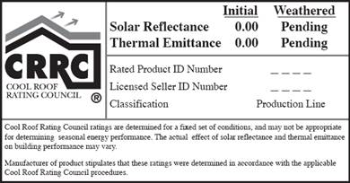
When a cool roof is installed to meet the prescriptive requirement or when it is used for compliance credit, the products must be tested and labeled by the CRRC as specified in §10-113. The CRRC is the supervisory entity responsible for certifying cool roof products. The CRRC test procedure is documented in CRRC-1, the CRRC Product Rating Program Manual. This test procedure includes tests for both solar reflectance and thermal emittance. See Figure 3-2 for an example of an approved CRRC product label.
Figure 3-2: Sample CRRC Product Label and Information
Source:
Cool Roof Rating Council
2. Solar Reflectance, Thermal Emittance, and Solar Reflectance Index (SRI)
§110.8(i)1-3
Both solar reflectance and thermal emittance are measured from 0 to 1; the higher the value, the "cooler" the roof. There are numerous roofing materials in a wide range of colors that have adequate cool roof properties. Excess heat can increase the air-conditioning load of a building, resulting in increased air-conditioning energy needed for maintaining occupant comfort. High-emitting roof surfaces reject absorbed heat quickly (upward and out of the building) than roof surfaces with low-emitting properties.
Solar Reflectance (SR). There are three measurements of solar reflectance:
1. Initial solar reflectance.
2. Three-year aged solar reflectance.
3. Accelerated aged solar reflectance.
All requirements of the Energy Standards are based on the three-year aged solar reflectance. If the aged value for the reflectance is not available in the CRRC’s Rated Product Directory, then the aged value shall be derived from the CRRC initial value or an accelerated testing process. Until the appropriate aged rated value for the reflectance is posted in the directory, or a new method of testing is used to find the accelerated solar reflectance, the equation below can be used to calculate the aged rated solar reflectance.
Aged Reflectancecalculated=(0.2+ β[ρinitial – 0.2])
Where,
ρinitial = Initial reflectance listed in the CRRC Rated Product Directory
β= 0.65 for field-applied coating, or 0.70 for not a field-applied coating
Thermal Emittance. The Energy Standards do not distinguish between initial and aged thermal emittance, meaning that either value can be used to demonstrate compliance with the Energy Standards.
Default Values. If a manufacturer fails to obtain CRRC certificate for its roofing products, the following default aged solar reflectance and thermal emittance values must be used for compliance:
a. For asphalt shingles, 0.08/0.75.
b. For all other roofing products, 0.10/0.75.
Solar Reflective Index (SRI). The temperature of a surface depends on the solar radiation incidence, surface reflectance, and emittance. The SRI measures the relative steady-state surface temperature of a surface with respect to standard white (SRI=100) and standard black (SRI=0) under the standard solar and ambient condition. A calculator has been produced that calculates the SRI by designating the solar reflectance and thermal emittance of the desired roofing material. The calculator can be found at http://www.energy.ca.gov/title24/2019standards . To calculate the SRI, the three-year aged solar reflectance value of the roofing product must be used. By using the SRI calculator, a cool roof may comply with a lower emittance, as long as the aged solar reflectance is higher and vice versa.
3. Field-Applied Liquid Coatings
There are several liquid products, including elastomeric coatings and white acrylic coatings that qualify for field-applied liquid coatings. The Energy Standards specify minimum performance and durability requirements for field-applied liquid coatings in Table 110.8-C depending on the type of coating. These requirements do not apply to industrial coatings that are factory-applied, such as metal roof panels. The requirements address elongation, tensile strength, permeance, and accelerated weathering.
4. Aluminum-Pigmented Asphalt Roof Coatings
Aluminum-pigmented coatings are silver-colored coatings that are commonly applied to modified bitumen and other roofing products. The coating has aluminum pigments that float to the surface of the coating and provides a shiny, surface. Because of the shiny surface and the physical properties of aluminum, these coatings have a thermal emittance below 0.75, which is the minimum rating for prescriptive compliance. The performance approach is typically used to achieve compliance with these coatings.
This class of field-applied liquid coatings shall be applied across the entire surface of the roof and meet the dry mil thickness or coverage recommended by the coating manufacturer, taking into consideration the substrate on which the coating will be applied. Also, the aluminum-pigmented asphalt roof coatings shall be manufactured in accordance with ASTM D2824. Standard specification is also required for aluminum-pigmented asphalt roof coatings, nonfibered, asbestos-fibered, and fibered without asbestos that are suitable for applying to roofing or masonry surfaces by brush or spray. Use ASTM D6848, Standard Specification for Aluminum Pigmented Emulsified Asphalt used as a Protective Coating for Roofing, installed in accordance with ASTM D3805, Standard Guide for Application of Aluminum-Pigmented Asphalt Roof Coatings.
a. Cement-Based Roof Coatings
This class of coatings consists of a layer of cement and has been used for a number of years in California’s Central Valley and other regions. These coatings may be applied to almost any type of roofing product. Cement-based coatings shall be applied across the entire roof surface to meet the dry mil thickness or coverage recommended by the manufacturer. Also, cement-based coatings shall be manufactured to contain no less than 20 percent Portland cement and meet the requirements of ASTM D822, ASTM C1583, and ASTM D5870.
b. Other Field-Applied Liquid Coatings
Other field-applied liquid coatings include elastomeric and acrylic-based coatings. These coatings must be applied across the entire surface of the roof to meet the dry mil thickness or coverage recommended by the coating manufacturer, taking into consideration the substrate on which the coating will be applied. The field-applied liquid coatings must be tested to meet performance and durability requirements as specified in Table 110.8-C of the Energy Standards or the minimum performance requirements of ASTM C836, D3468, D6083, or D6694, whichever are appropriate to the coating material.
3.2.4.2 Prescriptive Measures
A. Thermal Emittance and Solar Reflectance
§140.3(a)1A, TABLES 140.3-B, C, D
The prescriptive requirements call for roofing products to meet the solar reflectance and thermal emittance in both low-sloped and steep-sloped roof applications for nonresidential buildings. A qualifying roofing product under the prescriptive approach for a nonresidential building must have an aged solar reflectance and thermal emittance greater than or equal to that the values indicated in Table 3-2 below. Table 3-3 is for high-rise residential buildings and hotel/motel guest rooms, and Table 3-4 is for relocatable public school buildings where the manufacturer certifies use in all climate zones.
|
|
Climate Zones | |||||||||||||||||
|
1 |
2 |
3 |
4 |
5 |
6 |
7 |
8 |
9 |
10 |
11 |
12 |
13 |
14 |
15 |
16 | |||
|
Roofing Products |
Low-sloped |
Aged Reflectance |
0.63 |
0.63 |
0.63 |
0.63 |
0.63 |
0.63 |
0.63 |
0.63 |
0.63 |
0.63 |
0.63 |
0.63 |
0.63 |
0.63 |
0.63 |
0.63 |
|
Emittance |
0.75 |
0.75 |
0.75 |
0.75 |
0.75 |
0.75 |
0.75 |
0.75 |
0.75 |
0.75 |
0.75 |
0.75 |
0.75 |
0.75 |
0.75 |
0.75 | ||
|
SRI |
75 |
75 |
75 |
75 |
75 |
75 |
75 |
75 |
75 |
75 |
75 |
75 |
75 |
75 |
75 |
75 | ||
|
Steep-Sloped |
Aged Reflectance |
0.20 |
0.20 |
0.20 |
0.20 |
0.20 |
0.20 |
0.20 |
0.20 |
0.20 |
0.20 |
0.20 |
0.20 |
0.20 |
0.20 |
0.20 |
0.20 | |
|
Emittance |
0.75 |
0.75 |
0.75 |
0.75 |
0.75 |
0.75 |
0.75 |
0.75 |
0.75 |
0.75 |
0.75 |
0.75 |
0.75 |
0.75 |
0.75 |
0.75 | ||
|
SRI |
16 |
16 |
16 |
16 |
16 |
16 |
16 |
16 |
16 |
16 |
16 |
16 |
16 |
16 |
16 |
16 | ||
Energy Standards Table 140.3-B
|
|
Climate Zones | |||||||||||||||||
|
1 |
2 |
3 |
4 |
5 |
6 |
7 |
8 |
9 |
10 |
11 |
12 |
13 |
14 |
15 |
16 | |||
|
Roofing Products |
Low-sloped |
Aged Reflectance |
NR |
NR |
NR |
NR |
NR |
NR |
NR |
NR |
0.55 |
0.55 |
0.55 |
NR |
0.55 |
0.55 |
0.55 |
NR |
|
Emittance |
NR |
NR |
NR |
NR |
NR |
NR |
NR |
NR |
0.75 |
0.75 |
0.75 |
NR |
0.75 |
0.75 |
0.75 |
NR | ||
|
SRI |
64 |
64 |
64 |
64 |
64 |
64 |
64 |
64 |
64 |
64 |
64 |
64 |
64 |
64 |
64 |
64 | ||
|
Steep-Sloped |
Aged Reflectance |
NR |
0.20 |
0.20 |
0.20 |
0.20 |
0.20 |
0.20 |
0.20 |
0.20 |
0.20 |
0.20 |
0.20 |
0.20 |
0.20 |
0.20 |
NR | |
|
Emittance |
0.75 |
0.75 |
0.75 |
0.75 |
0.75 |
0.75 |
0.75 |
0.75 |
0.75 |
0.75 |
0.75 |
0.75 |
0.75 |
0.75 |
0.75 |
0.75 | ||
|
SRI |
16 |
16 |
16 |
16 |
16 |
16 |
16 |
16 |
16 |
16 |
16 |
16 |
16 |
16 |
16 |
16 | ||
Energy Standards Table 140.3-C
|
Roofing Products |
Aged Reflectance |
Emittance |
|
Low-Sloped |
0.63 |
0.75 |
|
SRI |
75 | |
|
Steep-Sloped |
0.20 |
0.75 |
|
SRI |
16 | |
Energy Standards Table 140.3-D
Exceptions to the minimum prescriptive requirements for solar reflectance and thermal emittance:
1. Roof area covered by building-integrated photovoltaic panels and building-integrated solar thermal panels is not required to meet the cool roof requirements.
2. If the roof construction has a thermal mass like gravel, concrete pavers, stone, or other materials with a weight of at least 25 lb/ft² over the roof membrane, then it is exempt from the above requirements for solar reflectance and thermal emittance.
3. Wood-framed roofs in climate zones 3 and 5 with a U- factor of 0.034 are exempt from the low-sloped cool roof requirement.
Where a low-sloped nonresidential roof’s aged reflectance is less than the prescribed requirement, insulation tradeoffs are available. By increasing the insulation level of a roof, a roofing product with a lower reflectance than the prescriptive requirements can be used to meet the cool roof requirements. The appropriate U-factor can be determined from Table 3-5 for nonresidential buildings based on roof type, climate zone and aged reflectance of at least 0.25.
|
Aged Solar Reflectance |
Metal Building Climate Zone 1-16 U-factor |
Wood-Framed and Other Climate Zone |
Wood Framed and Other All Other Climate Zones U-factor |
|
0.62-0.56 |
0.038 |
0.045 |
0.032 |
|
0.55-0.46 |
0.035 |
0.042 |
0.030 |
|
0.45-0.36 |
0.033 |
0.039 |
0.029 |
|
0.35 -0.25 |
0.031 |
0.037 |
0.028 |
B. Insulation Requirements − Exterior Roofs and Ceilings
§140.3(a)1B, TABLES 140.3-B, C, D
Under the prescriptive requirements, roofs or ceilings must have an assembly U-factor equal to or lower than the U-factor criterion for nonresidential or high-rise residential buildings. (See Table 3-6.) The U-factor values for exterior roofs and ceilings from Reference Joint Appendix JA4 must be used to determine compliance with the maximum assembly U-factor requirements. Alternatively, the assembly calculator that is incorporated into CBECC-COM, can be used to determine U-factors for assemblies and/or components not listed in JA4 tables.
The prescriptive requirement for metal building roofs require the entire cavity be filled with insulation. A common technique for standing seam metal roofs is to drape a layer of insulation over the purlins, using thermal blocks where the insulation is compressed at the supports. (See Figure 3-3A.) Either approach on insulation may be used in the Performance approach. However, there are significant benefits to using the “filled cavity” approach as shown in Figure 3-3B.
|
Building Type |
Climate Zones | ||||||||
|
1 |
2 |
3 |
4 |
5 |
6 |
7 |
8 | ||
|
Nonresidential |
Metal |
0.041 |
0.041 |
0.041 |
0.041 |
0.041 |
0.041 |
0.041 |
0.041 |
|
Wood-framing & Other framing type |
0.034 |
0.034 |
0.034 |
0.034 |
0.034 |
0.049 |
0.049 |
0.049 | |
|
High-Rise |
Metal |
0.041 |
0.041 |
0.041 |
0.041 |
0.041 |
0.041 |
0.041 |
0.041 |
|
Wood-framing & Other framing type |
0.028 |
0.028 |
0.034 |
0.028 |
0.034 |
0.034 |
0.039 |
0.028 | |
|
Relocatable Public School Buildings |
Metal Building |
0.041 |
0.041 |
0.041 |
0.041 |
0.041 |
0.041 |
0.041 |
0.041 |
|
Non-Metal Building |
0.034 |
0.034 |
0.034 |
0.034 |
0.034 |
0.034 |
0.034 |
0.034 | |
|
Building Type |
Climate Zones | ||||||||
|
9 |
10 |
11 |
12 |
13 |
14 |
15 |
16 | ||
|
Nonresidential |
Metal |
0.041 |
0.041 |
0.041 |
0.041 |
0.041 |
0.041 |
0.041 |
0.041 |
|
Wood-framing & Other framing type |
0.034 |
0.034 |
0.034 |
0.034 |
0.034 |
0.034 |
0.034 |
0.034 | |
|
High-Rise |
Metal |
0.041 |
0.041 |
0.041 |
0.041 |
0.041 |
0.041 |
0.041 |
0.041 |
|
Wood-framing & Other framing type |
0.028 |
0.028 |
0.028 |
0.028 |
0.028 |
0.028 |
0.028 |
0.028 | |
|
Relocatable Public School Buildings |
Metal Building |
0.041 |
0.041 |
0.041 |
0.041 |
0.041 |
0.041 |
0.041 |
0.041 |
|
Non-Metal Building |
0.034 |
0.034 |
0.034 |
0.034 |
0.034 |
0.034 |
0.034 |
0.034 | |
Summary of Tables 140.3-B, c, and 140.3-Dof the Energy Standards
Figure 3-3A: Standing Seam Metal Building Roof with Single Insulation Layer
![]()
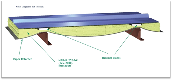
Source: North American Insulation Manufacturers Association (NAIMA)
Figure 3-3B – Filled Cavity Insulation for Metal Building Roofs
![]()
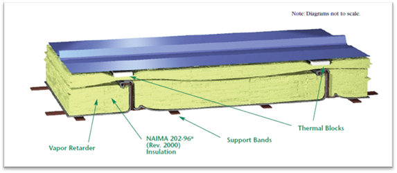
Source: North American Insulation Manufacturers Association (NAIMA)
A rigid polyisoyanurate (“polyiso”) thermal block with a minimum R-value of R-3.5 should be installed at the supports (a 1-inch-thick thermal block is recommended). The first rated R-value of the insulation is for faced insulation installed between the purlins. The second rated R-value of insulation represents unfaced insulation installed above the first layer, perpendicular to the purlins and compressed when the metal roof panels are attached. A supporting structure retains the bottom of the first layer at the prescribed depth required for the full thickness of insulation.
The bottom layer of insulation should completely fill the space between the purlins, and the support bands should be installed tightly to prevent the insulation from sagging.
The configuration above, which corresponds to two layers of R-19 and R-10 insulation, corresponds to the prescriptive requirement of U-0.041, but other insulation combinations exceeding the minimum requirement are readily achievable.
3.2.4.3 Performance Approach
Compliance options for roofing products and insulation. See Section 3.5 and Chapter 11 for more on the performance approach.
A. Aggregate Default Roof Reflectance Properties
Some low-sloped roofs of nonresidential buildings use aggregate material made of gravel or crushed stone that is 3/4" or smaller, as the surface layer under a ballasted roof. Such roofing cannot be accurately tested via CRRC procedures because some of the aggregate can become damaged in transit, affecting the performance.
The Energy Standards stipulate aged reflectance and emittance values that can be used for these types of products that have been tested via ASTM procedures. The default reflectance and emittance values may be used below in the performance compliance approach or prescriptive tradeoff with increased insulation per .
|
Aggregate Size |
Required Tested Initial Solar Reflectance |
Default Aged Solar Reflectance |
Default Thermal Emittance |
|
Built-Up
Roofs |
0.50 |
0.48 |
0.85 |
|
Ballasted Roofs |
0.45 |
0.40 |
0.85 |
For example, aggregate with size 2-4 meeting the requirements must have a tested solar reflectance of at least 0.45 to use a default aged reflectance value of 0.40 in the performance method.
Eligibility criteria for aggregate used as the surface layer of low-sloped roofs:
1. Aggregate shall have a tested initial solar reflectance that meets or exceeds 0.50 for built-up roofs and 0.45 for ballasted roofs using the ASTM E1918 test procedure conducted by an independent laboratory meeting the requirement of §10-113(d)4
2. Aggregate shall have a label on bags or containers of the aggregate material stating
(a) the tested initial solar reflectance of the material conforming to ASTM D1863, and (b) the size of the material conforming to ASTM D448.
Example 3-1
Question:
According to the provisions of the Energy Standards, are cool roofs mandatory for nonresidential buildings or high-rise residential buildings?
Answer:
No. Cool roofs are not mandatory. The prescriptive compliance requirements depend on the climate zone, building type and roof slope. Compliance with solar reflectance and thermal emittance, or SRI is required per Energy Standards Tables 140.3-B, C, and D. In the performance approach, reflectance, and emittance values less than the minimum prescriptive requirements may be used; however, any deficit that results from this choice must be made up by improving other energy efficiency features in the building, which include envelope, space-conditioning system, and lighting systems.
Example 3-2
Question:
Must all roofing materials used in California, whether cool roof or not, be certified by the CRRC and labeled accordingly?
Answer:
No. A roof repair, such as for a leak, or replacement of 50 percent or 2,000ft², whichever is more, does not require the roofing product to be cool roof or certified by the CRRC.
Yes, when altering your roof, such as a new reroof or replacement of 50 percent or 2,000ft², whichever is less, then, either the prescriptive envelope component approach or the performance approach can be used for compliance. In these cases, the roof must be certified and labeled by CRRC for nonresidential roofs. If you are using the performance approach to receive compliance credit, you can either obtain a CRRC certification, or use a default solar reflectance of 0.10 and thermal emittance of 0.75. Using default values instead of CRRC certificates may result in a significant energy penalty that must be made up by increasing energy efficiency in other building features. The default solar reflectance for asphalt shingles is 0.08.
Example 3-3
Question:
Can I use solar reflectance and thermal emittance data generated by any nationally recognized and well-respected laboratory in lieu of CRRC ratings? Can in-house testing by the manufacturer be used to qualify my product?
Answer:
No. Only CRRC ratings from the product directory list can be used to establish cool roof product qualification for standards compliance. The CRRC process requires use of a CRRC-accredited laboratory (under most circumstances, an "Accredited Independent Testing Laboratory (AITL) defined by the CRRC program.) Any testing laboratory can become an AITL by following the CRRC accreditation process and satisfying the requirements. The roster of CRRC-accredited laboratories is posted on the CRRC website (http://www.coolroofs.org).
Example 3-4
Question:
Can the reflectance and emittance requirements of ENERGY STAR® cool roofs be substituted for standards requirements?
Answer
No. Only roofing products which are listed by the CRRC in its Rated Product Directory can be used to the standards. CRRC is the only organization that has met the criteria set in §10-113.
Example 3-5
Question:
Can I claim to have a cool roof, or can I get anything higher than a default reflectance, if my roof does not meet the field-applied coating performance requirements of the Energy Standards?
Answer:
No, you cannot claim to have a cool roof and you cannot claim higher energy credits if your roof does not meet the coating performance requirements of the Energy Standards for field-applied coatings.
Example 3-6
Question:
How does a product get CRRC cool roof certification?
Answer:
Any party wishing to have a product or products certified by CRRC should contact the CRRC toll-free (866) 465-2523 from inside the United States or (510) 482-4420, ext. 215, or email info@coolroofs.org. In addition, CRRC publishes the procedures in the CRRC-1 Program Manual, available for free on http://www.coolroofs.org or by calling the CRRC. Working with CRRC staff is strongly recommended.
Example 3-7
Question:
Do alterations to the roof of an unconditioned building trigger cool roof requirements?
Answer:
No, alterations to the roof of an unconditioned building do not trigger cool roof requirements. In general, the lighting requirements are the only requirements applicable for both newly constructed and altered unconditioned buildings; this includes §140.3(c), the skylight requirements. Building envelope (other than skylight requirements) and space-conditioning requirements do not apply to unconditioned buildings.
Example 3-8
Question:
What happens if I have a low-sloped roof on most of my buildings and steep-sloped roof on another portion of the roof? Do I have to meet the two different sets of rules in §140.3(a)1Ai and ii?
Answer:
Yes, your building would have to meet both the low-sloped requirement and the steep-sloped roof requirements for the respective area.
Example 3-9
Question:
I am installing a garden roof (roofs whose surface is composed of soil and plants) on top of an office building. Although garden roofs are not cool roofs by their reflectance properties, will they be allowed under the Energy Standards?
Answer:
Yes, the Energy Commission considers a garden roof as a roof with thermal mass on it.
Under Exception 4 to §140.3(a)1Ai, if a garden roof has a dry unit weight of 25 lb/ft², then the garden roof is equivalent to cool roof.
The U-factor criteria for walls depend on the class of construction. U-factors used for compliance must be selected from Reference Joint Appendix JA4. Alternatively, the assembly calculator that is incorporated into CBECC-COM can be used to determine U-factors for assemblies and/or components not listed in JA4.
There are five common classes of wall constructions: wood-framed, metal-framed, metal building walls, light mass, and heavy mass. Figure 3-5. The following provides information about these wall systems, as well as furred walls and spandrel walls:
1. Wood-framed walls: As defined by the 2013 California Building Code, Type IV buildings typically have wood-framed walls. Framing members typically consist of 2x4 or 2x6 framing members spaced at 24 inch or 16 inch OC. Composite framing members and engineered wood products also qualify as wood framed walls if the framing members are nonmetallic. Structurally insulated panels (SIPs) are another construction type that qualifies as wood-framed. SIPs panels typically consist of rigid foam insulation sandwiched between two layers of oriented strand board (OSB). Reference Joint Appendix JA4, Table 4.3.1 has data for conventional wood-framed walls, and Table 4.3.2 has data for SIPs panels.
2. Metal-framed walls: Many nonresidential buildings and high-rise residential buildings require noncombustible construction, and this is achieved with metal-framed walls. Often metal-framed walls are not structural and are used as infill panels in rigid framed steel or concrete buildings. Batt insulation is less effective for metal-framed walls (compared to wood-framed walls) because the metal framing members are more conductive. In most cases, continuous insulation is required to meet prescriptive U-factor requirements. Reference Joint Appendix JA4, Table 4.3.3, has data for metal-framed walls.
3. Metal building walls: Metal building walls consist of a metal building skin that is directly attached to metal framing members. The framing members are typically positioned in a horizontal direction and spaced at about 4 ft. A typical method of insulating metal building walls is to drape the insulation over the horizontal framing members and to compress the insulation when the metal exterior panel is installed.
4. Light-mass walls: Light-mass walls have a heat capacity (HC) greater or equal to 7.0 but less than 15.0 Btu/°F-ft². See the definition below for heat capacity. From Reference Joint Appendix JA4, Tables 4.3.5 and 4.3.6 have U-factor, C-factor, and heat capacity data for hollow unit masonry walls, solid unit masonry and concrete walls, and concrete sandwich panels.
5. Heavy-mass walls: Have a HC equal to or greater than 15.0 Btu/°F-ft². See Reference Joint Appendix JA4 for HC data on mass walls.
Note: For light- and high-mass walls, heat capacity (HC) is the amount of heat required to raise the temperature of the material by 1 degree F. In the Energy Standards, it is defined as the product of the density (lb/ft3), specific heat (Btu/lb-F), and wall thickness (ft). For instance, a 6” medium weight concrete hollow unit masonry wall has a heat capacity of 8.4 and is considered a light mass wall. The same masonry wall with solid grout that is 10 inches thick has a heat capacity of 19.7 and is considered a heavy mass wall.
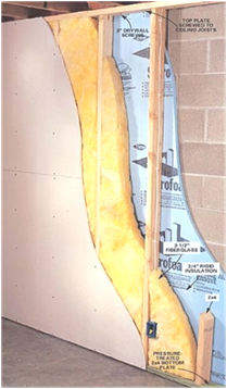
6. Furred walls: Are a specialty wall component, commonly applied to a mass wall type. See Figure 3-4 below. The Reference Joint Appendix JA4 Table 4.3.5, 4.3.6, or other masonry tables list alternative walls. Additional continuous insulation layers are selected from JA4 Table 4.3.13 and calculated using either Equation 4-1 or 4-4 from JA4. The effective R-value of the furred component depends upon the framing thickness, type, and insulation level.
Figure 3-4: Brick Wall With Furring Details
7. Spandrel panels and opaque curtain walls: These wall types consist of metalized or glass panels often hung outside structural framing to create exterior wall elements around fenestration and between floors. See Reference Joint Appendix JA4, Table 4.3.8 for U-factor data.
For some climate zones, mass walls and metal-framed walls require continuous insulation to meet the prescriptive U-factor requirements. When this is the case, the effect of the continuous insulation is estimated by Equation 4-1 in Reference Joint Appendix JA4.
Uprop = 1 / [ (1/Ucol,A) + Rcont,insul]
Framed or block walls can also have insulation installed between interior or exterior furring strips. The effective continuous R-value of the furring/insulation layer is shown in Table 4.3.13 of Reference Appendix JA4.
Example 3-10
Question :
An 8-inch
(20 cm) medium-weight concrete block wall with uninsulated cores has a layer of
1 inch (25 mm) thick exterior polystyrene continuous insulation with an R-value
of R-5. What is the U-factor for this assembly?
Answer:
From Reference Joint Appendix Table 4.3.5, the U-factor for the block wall is 0.53. From Equation 4-1, the U-factor is calculated as:
U= 1 / [ (1/0.53) + 5] = 0.145
Figure 3-5: Classes of Wall Construction

3.2.5.1 Mandatory Requirements
A. Wall Insulation
1. In addition to the mandatory requirements in § 110.8 for all buildings, Nonresidential, high–rise residential, hotels and motels must also meet the requirements in § 120.7
The opaque portions of walls that separate conditioned spaces from unconditioned spaces or ambient air shall meet these applicable requirements.
1. Metal Building: Weighted average U-factor of U-0.113 (single layer of R-13 batt insulation).
2. Metal-Framed: Weighted average U-factor of U-0.151 (R-8 continuous insulation, or R-13 batt insulation between studs and 1/2” of continuous rigid insulation of R-2). It may be possible to meet the area-weighted average U-factor without continuous insulation, if the appropriate siding materials are used.
3. Light Mass Walls: 6 inches or greater hollow core concrete masonry unit having a U-factor not exceeding 0.440 (partially grouted with insulated cells).
4. Heavy Mass Walls: 8 inches or greater hollow core concrete masonry unit having a U-factor not exceeding 0.690 (solid grout concrete, normal weight, 125 lb/ft3).
5. Wood-Framed and Others: Weighted average U-factor of U-0.110 (R-11 batt insulation).
6. Spandrel Panels and Opaque Curtain Wall: Weighted average U-factor of U-0.280.
Exception to Section 120.7: Buildings designed as data centers with high, constant server loads from the mandatory minimum requirements are exempt. To qualify for this exception, it should have a design computer room process load of 750 kW or greater.
3.2.5.2 Prescriptive Requirements
Under the prescriptive requirements, exterior walls must have an assembly U-factor equal to or lower than the U-factor criterion for nonresidential and high-rise residential buildings in Tables 140.3-B, C, D (see Table 3-8).
The U-factor for exterior walls from Reference Joint Appendix JA4 must be used to determine compliance with the assembly U-factor requirements. The Energy Standards does not allow using the R-value of the cavity or continuous insulation alone to demonstrate compliance with the insulation values of Reference Joint Appendix JA4; only U-factors may be used to demonstrate compliance.
For metal-framed walls with insulation between the framing sections, continuous insulation may need to be added to meet the U-factor requirements of the Energy Standards. For light mass walls, insulation is not required for buildings in South Coast climates but is required for other climates. For heavy mass walls, insulation is not required for buildings in Central Coast or South Coast climates but is required for other climates.
|
Building Type |
Climate Zones | ||||||||||||
|
1 |
2 |
3 |
4 |
5 |
6 |
7 |
8 | ||||||
|
Nonresidential |
Metal Building |
0.113 |
0.061 |
0.113 |
0.061 |
0.061 |
0.113 |
0.113 |
0.061 | ||||
|
Metal- Frame |
0.069 |
0.062 |
0.082 |
0.062 |
0.062 |
0.069 |
0.069 |
0.062 | |||||
|
Mass Light |
0.196 |
0.170 |
0.278 |
0.227 |
0.44 |
0.44 |
0.44 |
0.44 | |||||
|
Mass Heavy |
0.253 |
0.650 |
0.650 |
0.650 |
0.650 |
0.690 |
0.690 |
0.690 | |||||
|
Wood-Frame |
0.095 |
0.059 |
0.110 |
0.059 |
0.102 |
0.110 |
0.110 |
0.102 | |||||
|
Residential High-Rise |
Metal building |
0.061 |
0.061 |
0.061 |
0.061 |
0.061 |
0.061 |
0.061 |
0.061 | ||||
|
Metal-frame |
0.069 |
0.069 |
0.069 |
0.069 |
0.069 |
0.069 |
0.105 |
0.069 | |||||
|
|
Mass Light |
0.170 |
0.170 |
0.170 |
0.170 |
0.170 |
0.227 |
0.227 |
0.227 | ||||
|
Mass Heavy |
0.160 |
0.160 |
0.160 |
0.184 |
0.211 |
0.690 |
0.690 |
0.690 | |||||
|
Wood-Frame |
0.059 |
0.059 |
0.059 |
0.059 |
0.059 |
0.059 |
0.059 |
0.059 | |||||
|
Relocatable Public Schools |
Metal Building |
0.057 |
0.057 |
0.057 |
0.057 |
0.057 |
0.057 |
0.057 |
0.057 | ||||
|
Metal -Frame |
0.057 |
0.057 |
0.057 |
0.057 |
0.057 |
0.057 |
0.057 |
0.057 | |||||
|
Mass /7.0<HC |
0.170 |
0.170 |
0.170 |
0.170 |
0.170 |
0.170 |
0.170 |
0.170 | |||||
|
Wood Frame |
0.042 |
0.042 |
0.042 |
0.042 |
0.042 |
0.042 |
0.042 |
0.042 | |||||
|
All Other Walls |
0.059 |
0.059 |
0.059 |
0.059 |
0.059 |
0.059 |
0.059 |
0.059 | |||||
|
| |||||||||||||
|
Building Type |
Climate Zones | ||||||||||||
|
9 |
10 |
11 |
12 |
13 |
14 |
15 |
16 | ||||||
|
Nonresidential |
Metal Building |
0.061 |
0.061 |
0.061 |
0.061 |
0.061 |
0.061 |
0.057 |
0.061 | ||||
|
Metal-Frame |
0.062 |
0.062 |
0.062 |
0.062 |
0.062 |
0.062 |
0.062 |
0.062 | |||||
|
Mass Light |
0.44 |
0.170 |
0.170 |
0.170 |
0.170 |
0.170 |
0.170 |
0.170 | |||||
|
Mass Heavy |
0.690 |
0.650 |
0.184 |
0.253 |
0.211 |
0.184 |
0.184 |
0.160 | |||||
|
Wood-Frame |
0.059 |
0.059 |
0.045 |
0.059 |
0.059 |
0.059 |
0.042 |
0.059 | |||||
|
Residential High-Rise |
Metal Building |
0.061 |
0.061 |
0.057 |
0.057 |
0.057 |
0.057 |
0.057 |
0.057 | ||||
|
Metal-Frame |
0.069 |
0.069 |
0.069 |
0.069 |
0.069 |
0.069 |
0.048 |
0.069 | |||||
|
Mass Light |
0.196 |
0.170 |
0.170 |
0.170 |
0.170 |
0.170 |
0.170 |
0.170 | |||||
|
Mass Heavy |
0.690 |
0.690 |
0.184 |
0.253 |
0.211 |
0.184 |
0.184 |
0.160 | |||||
|
Wood-Frame |
0.059 |
0.059 |
0.042 |
0.059 |
0.059 |
0.042 |
0.042 |
0.042 | |||||
|
Relocatable Public Schools |
Metal Building |
0.057 |
0.057 |
0.057 |
0.057 |
0.057 |
0.057 |
0.057 |
0.057 | ||||
|
Metal -Frame |
0.057 |
0.057 |
0.057 |
0.057 |
0.057 |
0.057 |
0.057 |
0.057 | |||||
|
Mass /7.0<HC |
0.170 |
0.170 |
0.170 |
0.170 |
0.170 |
0.170 |
0.170 |
0.170 | |||||
|
Wood Frame |
0.042 |
0.042 |
0.042 |
0.042 |
0.042 |
0.042 |
0.042 |
0.042 | |||||
|
All Other Walls |
0.059 |
0.059 |
0.059 |
0.059 |
0.059 |
0.059 |
0.059 |
0.059 | |||||
3.2.6.1 Mandatory Insulation for Demising Walls
Demising walls separate conditioned space from enclosed unconditioned space. The insulation requirements include:
•Wood-framed: minimum of R-13 insulation (or have an equivalent U-factor of 0.099) between framing members.
•Metal-framed: minimum R-13 insulation (or a U-factor no greater than 0.151) between framing members plus R-2 continuous insulation.
•If it is not a framed assembly (constructed of brick, concrete masonry units, or solid concrete), then no insulation is required.
This requirement applies to buildings meeting compliance with either the prescriptive or performance approach.
EXCEPTION to Section 140.3(a)5A: Window area in demising walls is not counted as part of the window area for this requirement. Demising wall area is not counted as part of the gross exterior wall area or display perimeter for this requirement.
When an exterior door has 25 percent or more glazed area it is considered fenestration. See more on fenestration in Section 3.3.
3.2.7.1 Mandatory Requirements
Manufactured exterior doors shall have an air infiltration rate not exceeding:
•0.3 cfm/ft2 of door area for nonresidential single doors (swinging and sliding).
•1.0 cfm/ft2 of door area for nonresidential double doors (swinging).
3.2.7.2 Prescriptive Requirements
The Energy Standards define prescriptive requirements for exterior doors in Tables 140.3-B and Table 140.3-C. For swinging doors, the maximum U-factor is 0.70, and for non-swinging doors, the maximum allowed U-factor is 1.45 in Climate Zones 2 through 15 and 0.50 in Climate Zones 1 and 16. (See Table 3-9)
The swinging door requirement corresponds to uninsulated double-layer metal swinging doors. The 1.45 swinging door U-factor requirement corresponds to insulated single-layer metal doors or uninsulated single-layer metal roll-up doors and fire-rated doors. The 0.50 U-factor requirement for Climate Zones 1 and 16 corresponds to wood doors with a minimum nominal thickness of 1 ¾ inches. For more information, consult Reference Appendix JA4, Table 4.5.1.
When glazing area is 25 percent or more of the entire door area, it is then defined as a fenestration product in the Energy Standards, and the entire door area is modeled as a fenestration unit. If the glazing area is less than 25 percent of the door area, the glazing must be modeled as the glass area plus two inches in each direction of the opaque door surface (to account for a frame). However, exterior doors are part of the gross exterior wall area and must be considered when calculating the window to wall ratio.
|
Building
|
Door Type |
Climate Zones | |||||||
|
1 |
2 |
3 |
4 |
5 |
6 |
7 |
8 | ||
|
Nonresidential |
Non-Swinging |
0.50 |
1.45 |
1.45 |
1.45 |
1.45 |
1.45 |
1.45 |
1.45 |
|
Swinging |
0.70 |
0.70 |
0.70 |
0.70 |
0.70 |
0.70 |
0.70 |
0.70 | |
|
High-Rise Residential |
Non-Swinging |
0.50 |
1.45 |
1.45 |
1.45 |
1.45 |
1.45 |
1.45 |
1.45 |
|
Swinging |
0.70 |
0.70 |
0.70 |
0.70 |
0.70 |
0.70 |
0.70 |
0.70 | |
|
Relocatable Public Schools |
Non-Swinging |
0.50 |
0.50 |
0.50 |
0.50 |
0.50 |
0.50 |
0.50 |
0.50 |
|
Swinging |
0.70 |
0.70 |
0.70 |
0.70 |
0.70 |
0.70 |
0.70 |
0.70 | |
|
Building
|
Door Type |
Climate Zones | |||||||
|
9 |
10 |
11 |
12 |
13 |
14 |
15 |
16 | ||
|
Nonresidential |
Non-Swinging |
1.45 |
1.45 |
1.45 |
1.45 |
1.45 |
1.45 |
1.45 |
0.50 |
|
Swinging |
0.70 |
0.70 |
0.70 |
0.70 |
0.70 |
0.70 |
0.70 |
0.70 | |
|
High-Rise Residential |
Non-Swinging |
1.45 |
1.45 |
1.45 |
1.45 |
1.45 |
1.45 |
1.45 |
0.50 |
|
Swinging |
0.70 |
0.70 |
0.70 |
0.70 |
0.70 |
0.70 |
0.70 |
0.70 | |
|
Relocatable Public Schools |
Non-Swinging |
0.50 |
0.50 |
0.50 |
0.50 |
0.50 |
0.50 |
0.50 |
0.50 |
|
Swinging |
0.70 |
0.70 |
0.70 |
0.70 |
0.70 |
0.70 |
0.70 |
0.70 | |
Energy Standards Table 140.3-B, Table 140.3-C, and 140.3-D
The U-factor criteria for concrete raised floors depend on whether the floor is a mass floor or not. A mass floor is one constructed of concrete with a heat capacity (HC) greater than or equal to 7.0 Btu/°F-ft².
Insulation levels
for nonresidential concrete raised floors with HC ≥ 7.0 using
U-factor for
compliance, from Reference Joint Appendix JA4, Table
4.4.6, are equivalent to no insulation in Climate Zones 3-10 and associated
U-factors to continuous insulation of R-8 in climate zones 1, 2, 11 through 15;
and R-15 in climate zone 16.
To determine the U-factor insulation levels for high-rise residential concrete raised floors, use the U-factors that are associated with R-8 continuous insulation in climate zones 7 through 9; R-15 in climate zones 3-5 and 11-13; with additional insulation required in climate zones 1, 2, 14 and 16.
Table 4.4.6 from Reference Joint Appendix JA4 is used with mass floors while Tables 4.4.1 through 4.4.5 are used for non-mass floors. (See Figure 3-6.)
Figure 3-6: Classes of Floor Constructions

3.2.8.1 Mandatory Requirements
A. Insulation Requirements for Heated Slab Floors
Heated slab-on-grade floors must be insulated according to the requirements in TABLE 110.8-A of the Energy Standards (Table 3-10). The top of the insulation must be protected with a rigid shield to prevent intrusion of insects into the building foundation, and the insulation must be capable of withstanding water intrusion.
A common location for the slab insulation is on the foundation perimeter. Insulation that extends downward to the top of the footing is acceptable. Otherwise, the insulation must extend downward from the level of the top of the slab, down 16 inches (40 cm) or to the frost line, whichever is greater.
For below-grade slabs, vertical insulation shall be extended from the top of the foundation wall to the bottom of the foundation (or the top of the footing) or to the frost line, whichever is greater.
Another option is to install the insulation inside the foundation wall and between the heated slab. In this case insulation must extend downward to the top of the footing and then extend horizontally inward, under the slab, a distance of 4 feet toward the center of the slab. R-5 vertical insulation is required in all climates except Climate Zone 16, which requires R-10 of vertical insulation and R-7 horizontal insulation.
Figure 3-7: Perimeter Slab Insulation

Note: The California Mechanical Code should be consulted when constructing a heated slab.
|
Insulation Location |
Insulation Orientation |
Installation Requirements |
Climate Zone |
Insulation R-Value |
|
Outside edge of heated slab, either inside or outside the foundation wall |
Vertical |
From the level of the top of the slab, down 16 inches or to the frost line, whichever is greater. Insulation may stop at the top of the footing where this is less than the required depth. For below-grade slabs, vertical insulation shall be extended from the top of the foundation wall to the bottom of the foundation (or the top of the footing) or to the frost line, whichever is greater. |
1 – 15 |
5 |
|
16 |
10 | |||
|
Between heated slab and outside foundation wall |
Vertical and Horizontal |
Vertical insulation from top of slab at inside edge of outside wall down to the top of the horizontal insulation. Horizontal insulation from the outside edge of the vertical insulation extending 4 feet toward the center of the slab in a direction normal to the outside of the building in plain view. |
1 – 15 |
5 |
|
16 |
10 vertical and 7 horizontal |
Energy Standards TABLE 110.8-A
B. Floor and Soffit Insulation
1. Raised Mass Floors: A minimum of 3 inches of lightweight concrete over a metal deck or the weighted average U-factor of the floor assembly shall not exceed U-0.269.
2. Other Floors: Weighted average U-factor of U-0.071.
3. Heated Slab Floor: A heated slab floor shall be insulated to meet the requirements of § 110.8(g).
Figure 3-8: Requirements for Floor/Soffit Surfaces

3.2.8.2 Prescriptive Requirements
A. Exterior Floors and Soffits
Under the prescriptive requirements, exterior floors and insulated soffits must have an assembly U-factor equal to or lower than the U-factor criterion for nonresidential, high-rise residential buildings and relocatable public school buildings in Tables 140.3-B, C, D (Table 3-11). The U-factor for exterior floors and soffits from Reference Joint Appendix JA4 shall be used to determine compliance with the maximum assembly U-factor requirements. The Energy Standards do not allow using the R-value of the cavity or continuous insulation alone to demonstrate compliance with the insulation values of JA4; only U-factors may be used to demonstrate compliance. For metal-framed floors, batt insulation between framing section may need continuous insulation to be modeled and installed on the interior or exterior to meet the U-factor requirements of the Energy Standards.
|
Building
|
Floor Type |
Climate Zones | |||||||
|
1 |
2 |
3 |
4 |
5 |
6 |
7 |
8 | ||
|
Nonresidential |
Mass |
0.092 |
0.092 |
0.269 |
0.269 |
0.269 |
0.269 |
0.269 |
0.269 |
|
Other |
0.048 |
0.039 |
0.071 |
0.071 |
0.071 |
0.071 |
0.071 |
0.071 | |
|
High-Rise Residential |
Mass |
0.045 |
0.045 |
0.058 |
0.058 |
0.058 |
0.069 |
0.092 |
0.092 |
|
Other |
0.034 |
0.034 |
0.039 |
0.039 |
0.039 |
0.039 |
0.071 |
0.039 | |
|
Relocatable Public Schools |
All |
0.48 |
0.48 |
0.48 |
0.48 |
0.48 |
0.48 |
0.48 |
0.48 |
|
Building
|
Floor Type |
Climate Zones | |||||||
|
9 |
10 |
11 |
12 |
13 |
14 |
15 |
16 | ||
|
Nonresidential |
Mass |
0.269 |
0.269 |
0.092 |
0.092 |
0.092 |
0.092 |
0.092 |
0.058 |
|
Other |
0.071 |
0.071 |
0.039 |
0.071 |
0.071 |
0.039 |
0.039 |
0.039 | |
|
High-Rise Residential |
Mass |
0.092 |
0.069 |
0.058 |
0.058 |
0.058 |
0.045 |
0.058 |
0.037 |
|
Other |
0.039 |
0.039 |
0.039 |
0.039 |
0.039 |
0.034 |
0.039 |
0.034 | |
|
Relocatable Public Schools |
All |
0.48 |
0.48 |
0.48 |
0.48 |
0.48 |
0.48 |
0.48 |
0.48 |
Summary from Energy Standards Tables 140.3-B, 140.3-C, and 140.3-D