Manufacturers must certify that their products comply with California’s Title 20 Appliance Efficiency Regulations, Section 1605.1(f) at the time of manufacture. Regulated equipment that applies to all of the aforementioned system types in Section 5.2 must be listed in the California Energy Commission Appliance Efficiency Database.
Water heaters are regulated under California’s Title 20 Appliance Efficiency Regulations, Section 1605.1(f). These regulations align with the federal efficiency standards for water heaters. Consumer water heaters and residential-duty commercial water heaters are both rated in Uniform Energy Factor (UEF). The draw pattern is based on the water heater’s design first hour rating for storage water heater, or gallon per minute for instantaneous water heaters. The efficiency requirements for the most common consumer water heaters are given in Table 5.4 below. The efficiency requirements for the residential-duty commercial water heaters are given in Table 5-5 below.
The Energy Commission has developed a water heater efficiency guide to allow quick lookup of the minimum efficiency of the most common types and sizes of water heaters. It is available to download here:
http://www.energy.ca.gov/title24/orc/waterheating/2019_waterheating.html#resguides
|
Product class |
Rated storage volume |
Draw pattern |
UEF |
|
Gas-fired Storage Water Heater |
≥20 gal and ≤55 gal |
Very Small |
0.3456 − (0.0020 × Vr) |
|
|
Low |
0.5982 − (0.0019 × Vr) | |
|
|
Medium |
0.6483 − (0.0017 × Vr) | |
|
|
High |
0.6920 − (0.0013 × Vr) | |
|
|
>55 gal and ≤100 gal |
Very Small |
0.6470 − (0.0006 × Vr) |
|
|
Low |
0.7689 − (0.0005 × Vr) | |
|
|
Medium |
0.7897 − (0.0004 × Vr) | |
|
|
High |
0.8072 − (0.0003 × Vr) | |
|
Electric Storage Water Heaters |
≥20 gal and ≤55 gal |
Very Small |
0.8808 − (0.0008 × Vr) |
|
|
Low |
0.9254 − (0.0003 × Vr) | |
|
|
Medium |
0.9307 − (0.0002 × Vr) | |
|
|
High |
0.9349 − (0.0001 × Vr) | |
|
|
>55 gal and ≤120 gal |
Very Small |
1.9236 − (0.0011 × Vr) |
|
|
Low |
2.0440 − (0.0011 × Vr) | |
|
|
Medium |
2.1171 − (0.0011 × Vr) | |
|
|
High |
2.2418 − (0.0011 × Vr) | |
|
Instantaneous Gas-fired Water Heater |
<2 gal and >50,000 Btu/h |
Very Small |
0.80 |
|
|
Low/Medium/High |
0.81 | |
|
Instantaneous Electric Water Heater |
<2 gal |
Very Small/Low/Medium |
0.91 |
|
|
High |
0.92 | |
|
Grid-Enabled Water Heater |
>75 gal |
Very Small |
1.0136 − (0.0028 × Vr) |
|
|
Low |
0.9984 − (0.0014 × Vr) | |
|
|
Medium |
0.9853 − (0.0010 × Vr) | |
|
|
High |
0.9720 − (0.0007 × Vr) | |
|
Vr= Rated Storage Volume – the water storage capacity of a water heater (in gallons). | |||
Source: U.S. Department of Energy
|
Product class |
Specifications |
Draw pattern |
UEF |
|
Gas-Fired Storage |
>75 kBTU/hr and ≤105 kBTU/hr and ≤120 gal |
Very Small |
0.2674 − (0.0009 × Vr) |
|
Low |
0.5362 − (0.0012 × Vr) | ||
|
|
Medium |
0.6002 − (0.0011 × Vr) | |
|
|
High |
0.6597 − (0.0009 × Vr) | |
|
Oil-Fired Storage |
>105 kBTU/hr and ≤140 kBTU/hr and ≤120 gal |
Very Small |
0.2932 − (0.0015 × Vr) |
|
Low |
0.5596 − (0.0018 × Vr) | ||
|
|
Medium |
0.6194 − (0.0016 × Vr) | |
|
|
High |
0.6740 − (0.0013 × Vr) | |
|
Electric Instantaneous |
>12 kW and ≤58.6 kW and ≤2 gal |
All draw pattern |
0.80 |
For commercial water heaters, unlike consumer water heaters, these water heaters are not rated in UEF. The required minimum energy efficiency for commercial water heaters are defined as thermal efficiency and standby loss, as shown in Table 5-6 below.
|
Input-to-Volume Ratio |
Size (Volume) |
Minimum Thermal Efficiency (%) |
Maximum Standby Loss¹,² | |
|
Gas storage water heaters |
< 4,000 BTU/hr/gal |
any |
80 |
Q/800 + 110(Vr)1/2 BTU/hr |
|
Gas instantaneous water heaters |
≥ 4,000 BTU/hr/gal |
< 10 gal |
80 |
– |
|
≥ 10 gal |
80 |
Q/800 + 110(Vr)1/2 BTU/hr | ||
|
Gas hot water supply boilers |
≥ 4,000 BTU/hr/gal |
< 10 gal |
80 |
– |
|
≥ 10 gal |
80 |
Q/800 + 110(Vr)1/2 BTU/hr | ||
|
Oil storage water heaters |
< 4,000 BTU/hr/gal |
any |
78 |
Q/800 + 110(Vr)1/2 BTU/hr |
|
Oil instantaneous water heaters |
≥ 4,000 BTU/hr/gal |
< 10 gal |
80 |
– |
|
≥ 10 gal |
78 |
Q/800 + 110(Vr)1/2 BTU/hr | ||
|
Oil hot water supply boilers |
≥ 4,000 BTU/hr/gal |
< 10 gal |
80 |
– |
|
≥ 10 gal |
78 |
Q/800 + 110(Vr)1/2 BTU/hr | ||
|
Electric storage water heaters |
< 4,000 BTU/hr/gal |
any |
– |
0.3 + 27/Vm %/hr |
|
1. Standby loss is based on a 70° F temperature difference between stored water and ambient requirements. In the standby loss equations, Vr is the rated volume in gallons, Vm is the measured volume in gallons, and Q is the nameplate input rate in BTU/hr. 2. Water heaters and hot water supply boilers having more than 140 gallons of storage capacity are not required to meet the standby loss requirement if the tank surface is thermally insulated to R-12.5, if a standing pilot light is not installed, and for gas- or oil-fired storage water heaters, there is a flue damper or fan-assisted combustion. | ||||
Source: California Energy Commission, Title 20 Appliance Efficiency Regulations (2014)
All newly installed instantaneous water heaters (minimum input of 6.8 kBTU/hr) shall have isolation valves on both the incoming cold water supply and the hot water pipe leaving the water heater. Isolation valves assist in the flushing of the heat exchanger and help prolong the life of instantaneous water heaters. Instantaneous water heater that has integrated drain ports for servicing are acceptable to meet the requirements of §110.3(c)7 and will not require additional isolation valves.
To facilitate future installations of high-efficiency equipment, the Energy Standards contain the following mandatory requirements for systems using gas or propane water heaters that serve individual dwelling units.
These requirements are for new construction and additions (if a water heater is installed in the added floor area), and they are not applicable to alterations. Moreover, these requirements are not applicable when installing an electric water heater.
1. A dedicated 125-volt (V) electrical receptacle that is within 3 feet of the water heater and accessible to the water heater with no obstructions, and be connected to a three conductor, 10 AWG branch circuit. In addition, the unused conductor must be labeled and electrically isolated and have a reserved circuit breaker space.
2. A Category III or IV vent or a Type B vent with a straight pipe between the outside termination and the space where the water heater is installed
3. A condensate drain that is no more than 2 inches higher than the base of the installed water heater and allows natural draining without pump assistance
4. A gas supply line with a capacity to provide at least 200,000 BTU/hr to the water heater.
These requirements make it easier for someone to retrofit HPWH or high efficiency gas water heaters in the future. Virtually all high efficiency gas water heaters require an electrical connection and wiring during initial construction stage is much less costly than trying to retrofit it later.
5.3.4.1 Electrical Receptacle
The goal of this requirement is to allow easy installation of HPWH when the existing gas water heater needs to be replaced. HPWH typically requires a 240-volt circuit and this requirement allows an electrician to easily convert the 120-volt circuit to a 240-volt circuit.
The electrical receptacle must be installed with 3 feet from the water heater. It should be connected to a dedicated circuit with a 10 AWG copper branch circuit. The ends of the unused conductor must be labeled as “spare”, and be electrically isolated.
A reserved single pole circuit breaker space must be placed in the electrical panel next to the circuit breaker for the branch circuit and labeled with the words “Future 240V Use.”
5.3.4.2 Venting
Table 5-7 below summarizes venting requirements for different types of water heaters. Higher efficiency water heaters often require different vent materials due to the presence of acidic condensation from flue gases. The standard Type B vent installed for conventional atmospheric gas water heaters is made of steel and would soon be destroyed by the condensate. As a result, the Energy Standards require that a Type B vent for the water heater can be installed only when there is a straight shot between the water heater and where the vent leaves the building. There should be no bends along the path of the Type B vent, except the portion of the Type B vent outside the building and in the space where the water heater is installed. The installation shall meet all code and manufacturers’ guidelines. Because Category III and IV pipes are usually smaller than those for Type B vents, a straight Type B vent can be easily modified into a Category III or IV vent by simply inserting a new vent pipe through the existing Type B vent pipe. A flue pipe that makes bends though the building structure is not easy to retrofit, and, thus, these flues must be either Category III or IV vent pipes. Only stainless steel Category III and IV vents are compatible with typical atmospheric combustion storage water heaters.
|
Appliance Venting Category |
Vent Pressure |
Condensing or Non-Condensing |
Common Vent Pipe Material |
|
Category I: An appliance that operates with a nonpositive vent static pressure and with a vent gas temperature that avoids excessive condensate production in the vent |
Nonpositive; atmospheric-vented; gravity-vented; most common category of gas-fired water heaters. |
Noncondensing (typically less than 82% efficiency)
|
Metal double wall “B” vent
|
|
Category II: An appliance that operates with a nonpositive vent static pressure and with a vent gas temperature that may cause excessive condensate production in the vent |
Nonpositive |
Condensing |
Special venting material per the product manufacturer |
|
Category III: An appliance that operates with a positive vent static pressure and with a vent gas temperature that avoids excessive condensate production in the vent |
Positive (usually created by a blower motor); generally cannot be adjoined to gravity-vented water heater. |
Noncondensing (typically less than 82% efficiency)
|
Stainless steel; these usually require 3” clearance to combustibles and the joints must be sealed air tight. |
|
Category IV: An appliance that operates with a positive vent static pressure and with a vent gas temperature that avoids excessive condensate production in the vent |
Positive (usually created by a blower motor); generally cannot be adjoined to gravity-vented water heater. |
Condensing |
Plastic pipe (PVC, CPVC, ABS, etc.) |
The requirement for the condensate drain being placed near the water heater and no higher than the base of the tank allows the condensate to be removed without relying on a sump pump.
5.3.4.4 Gas Line
Designing the gas line to provide 200,000 BTU per hour gas supply capacity to the water heater is required to accommodate future retrofit to a gas instantaneous water heater, which usually has a heat input capacity of 199,000 BTU/hr or higher. Similar to the electrical requirement, installing a larger gas line during new construction is inexpensive relative to a future gas line retrofit.
Gas pipe sizing for the building needs to consider piping layout and gas supply requirements for other gas appliances, such as gas clothes dryers, gas furnaces, gas ranges and ovens, and gas fireplace burners. The traditional practice of using a ½-inch gas pipe in a single-family house to serve a storage water heater is not in compliance with the mandatory requirement. The minimum gas pipe size for water heaters is ¾-inch. The exact gas piping system should be designed following the California Plumbing Code.
5.3.5.1 Pipe Insulation for All Buildings
All domestic hot water piping shall be insulated as specified in Section 609.11 of the California Plumbing Code, which requires pipe insulation thickness equal to or more than the diameter of the pipe, up to 2 inches. Above pipe diameter of 2 inches, the insulation thickness must be at least 2 inches. In addition, the following piping conditions shall have a minimum insulation wall thickness of 1 inch:
1. The first 5 feet of hot and cold water pipes from the storage tank or water heater.
2. All piping with a nominal diameter of ¾ inch or larger.
3. All piping associated within a domestic hot water recirculation system regardless of the pipe diameter. This excludes branches off the recirculation loop that are less than ¾ inch diameter or do not serve the kitchen.
4. Piping from the heating source to a storage tank or between tanks.
5. Piping buried below grade.
6. All hot water pipes from the heating source to the kitchen fixtures.
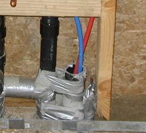
In addition to insulation requirements, all domestic hot water pipes that are buried below grade must be installed in a waterproof and noncrushable casing or sleeve. The installation shown in Figure 5-4 below would not meet the installation requirements since it is not insulated. In addition, in Figure 5-4 the hot and cold water lines are not separated. Heat transfer will occur, resulting in energy loss and causing condensation on the cold water line.
Figure 5-4: Noncompliant Below-Grade Piping and Hot and Cold Water Lines Separation
Source: Davis Energy Group/Frontier Energy
A. Piping exempt From the Mandatory Insulation Includes:
1. Factory-installed piping within space conditioning equipment.
2. Piping that serves process loads, gas piping, cold domestic water piping (other than within 5 feet of the water heater), condensate drains, roof drains, vents, or waste piping.
3. Piping that penetrates framing members. This piping is not required to have insulation where it penetrates the framing. However, if the framing is metal, then some insulating material must prevent contact between the pipe and the metal framing.
4. Piping located within exterior walls that are installed so that piping is placed inside wall insulation. Wall insulation may be an acceptable alternative insulation method for sections of pipes that would otherwise need pipe insulation, as long as the wall insulation in the walls where the pipes are located meets the requirements of QII and the pipes are roughly centered in the wall cavity. (see Reference Appendix RA4.4.1).
5. Piping in the attic continuously buried by at least 4 inches of blown-in ceiling insulation. Piping may not be placed directly in contact with sheetrock and then covered with insulation to meet this requirement.
B. Other installation information:
1. No insulation should be installed closer than 6 inches from the flue. If possible, bend the pipe away from the flue. Otherwise, it may be necessary to stop pipe insulation short of the storage tank. (See the current version of the California Mechanical Code.)
2. All pipe insulation seams must be sealed.
3. Installed piping may not be located in supply or return air plenums. (See the current version of the California Mechanical Code.)
4. Hot and cold water piping, when installed in parallel runs, must be at least 2 inches apart. (See Reference Appendix RA4.)
5. If a fire wall interrupts the first 5 feet of pipe, the insulation may be interrupted at the wall and continued on the other side.
6. Insulation for pipe elbows should be mitered and insulation for tees should be notched. (See Reference Appendix RA4.)
Figure 5-5: Pipe Insulation Requirements First Five Feet From Water Heater

Source: California Energy Commission
|
Fluid Operating Temperature Range
|
Insulation Conductivity |
|
Nominal Pipe Diameter (in inches) | |||||
|
Conductivity |
Mean Rating Temperature (°F) |
< 1 |
1 to <1.5 |
1.5 to < 4 |
4 to < 8 |
8 and larger | ||
|
Space-Heating and Service Water-Heating Systems (Steam, Steam Condensate, Refrigerant, Space Heating, Service Hot Water) |
Minimum Pipe Insulation Required (Thickness in inches or R-value) | |||||||
|
Above 350 |
0.32-0.34 |
250 |
Inches |
4.5 |
5.0 |
5.0 |
5.0 |
5.0 |
|
R-value |
R 37 |
R 41 |
R 37 |
R 27 |
R 23 | |||
|
251-350 |
0.29-0.32 |
200 |
Inches |
3.0 |
4.0 |
4.5 |
4.5 |
4.5 |
|
R-value |
R 24 |
R 34 |
R 35 |
R 26 |
R 22 | |||
|
201-250 |
0.27-0.30 |
150 |
Inches |
2.5 |
2.5 |
2.5 |
3.0 |
3.0 |
|
R-value |
R 21 |
R 20 |
R 17.5 |
R 17 |
R 14.5 | |||
|
141-200 |
0.25-0.29 |
125 |
Inches |
1.5 |
1.5 |
2.0 |
2.0 |
2.0 |
|
R-value |
R 11.5 |
R 11 |
R 14 |
R 11 |
R 10 | |||
|
105-140 |
0.22-0.28 |
100 |
Inches |
1.0 |
1.5 |
1.5 |
1.5 |
1.5 |
|
R-value |
R 7.7 |
R 12.5 |
R 11 |
R 9 |
R 8 | |||
Source Excerpt From Table 120.3 A of the Energy Standards
Where insulation is required as described above, 1 inch of insulation is typically required. This requirement applies to domestic hot water pipe (above 105° F) when the pipe diameter is 1 inch or smaller, the water temperature is between 105°F and 140°F, and the insulation conductivity is between 0.22 and 0.28 BTU-in/hr-ft²-°F (typical of cellular foam pipe insulation material). One and one-half inch insulation is required on pipes greater than 1 inch. For other situations refer to Table 120.3 A.
5.3.5.2 Insulation Protection
If hot water piping insulation is exposed to weather, it must be protected from physical damage, ultraviolet (UV) light deterioration, and moisture. Insulation is typically protected by aluminum, sheet metal, painted canvas, plastic cover, or a water-retardant coating that shields from solar radiation. Adhesive tape should not be used as insulation cover because removal of the tape will damage the integrity of the original insulation during preventive maintenance.
5.3.5.3 Distribution Systems Serving Multiple Dwelling Units – With Recirculation Loops
Multifamily buildings may have water heaters for each dwelling unit but are more likely to have a central water heating system with a recirculation loop that supplies each of the units. This recirculation loop consists of a supply portion of larger diameter pipe connected to smaller diameter branches that serve multiple dwelling units, guest rooms, or common area fixtures and a return portion that completes the loop back to the water heating equipment. The large volume of water that is recirculated during periods of high use creates situations that require the installation of certain controls and servicing mechanisms to optimize performance and allow for lower cost of maintenance. The following paragraphs cover the mandatory requirements for system serving multiple dwelling units and with recirculation loops.
The constant supply of new water in combination with the continuous operation of pumps creates the possibility of the pump cavitation due to the presence of air in the water. Cavitation is the formation of bubbles in the low-pressure liquid on the suction side of the pump. The cavities or bubbles will collapse when they pass into the higher regions of pressure, causing noise and vibration that may lead to damage to many of the components. In addition, there is a loss in capacity, and the pump can no longer build the same head (pressure). This ultimately affects the efficiency and life expectancy of the pump.
Cavitation shall be minimized either by installing an air release valve or mounting the pump vertically. The air release valve must be located no more than 4 feet from the inlet of the pump. The air release valve must also be mounted on a vertical riser with a length of at least 12 inches.
Temperature and pressure differences in the water throughout a recirculation system can create backflows. This can result in cooler water from the bottom of the water heater tank and water near the end of the recirculation loop flowing backward toward the hot water load and reducing the delivered water temperature.
To prevent this from occurring, the Energy Standards require that a check valve or similar device be located between the recirculation pump and the water heating equipment.
A large number of systems are allowed to operate until complete failure simply because of the difficulty of repair or servicing. Repair labor costs can be reduced significantly by planning and designing for easy pump replacement when the pump fails. Provision for pump priming and pump isolation valves helps reduce maintenance costs.
To meet the pump priming equipment requirement, a hose bib must be installed between the pump and the water heater. In addition, an isolation valve shall be installed between the hose bib and the water heating equipment. This configuration will allow the flow from the water heater to be shut off, allowing the hose bib to be used for bleeding air out of the pump after pump replacement.
The requirement for the pump isolation valves will allow replacement of the pump without draining a large portion of the system. The isolation valves shall be installed on both sides of the pump. These valves may be part of the flange that attaches the pump to the pipe. One of the isolation valves may be the same isolation valve as in Item C.
Manufacturer’s specifications should always be followed to assure optimal performance of the system. The cold water piping and the recirculation loop piping should never be connected to the hot water storage tank drain port.
The dynamic between the water in the heater and the cold water supply are similar to those in the recirculation loop. Thermosyphoning can occur on this side of this loop just as it does on the recirculation side of the system. To prevent this, the Energy Standards require a check valve to be installed on the cold water supply line. The valve should be located between the hot water system and the next closest tee on the cold water supply line. The system shall comply with the expansion tank requirements as described in the California Plumbing Code.
Figure 5-6: Mandatory Central Recirculation System Installation Requirements
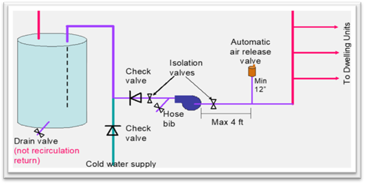
Source: California Energy Commission
Example 5-1 − Distribution Systems
Question:
When I'm insulating the pipes for a recirculating water heating system, I understand that I must insulate the entire length of hot water pipes that are part of the recirculation loop. Do I also need to insulate the runouts?
Answer:
No, other than the pipe to the kitchen fixture as it is a mandatory requirement. Since the water in runouts does not recirculate, other runouts do not need to be insulated.
Example 5-2 − Recirculation System Insulation
Question:
Can I get pipe insulation credit for a recirculating water heating system?
Answer:
Not for systems serving a single dwelling unit. Recirculating water heating systems have a mandatory insulation requirement for the recirculating section of the hot water pipes; pipes less than 1 inch must be insulated to 1 inch of insulation. For systems serving multiple dwelling units, using thicker-than-required insulation results in credit within the performance approach. All the circulation loop pipes in one location type (for example, inside, outside, underground) must be insulated to the higher level to qualify.
Example 5-3 − Pipe Insulation
Question:
I thought I was supposed to insulate hot and cold water piping from the water heater for either the first 5 feet or the length of piping before coming to a wall, whichever is less. Did I misunderstand?
Answer:
Yes. The requirement is that you must insulate the entire length of the first 5 ft, regardless of whether there is a wall (§150.0[j]2). You have two options: (1) interrupt insulation for a fire wall and continue it on the other side of the wall or (2) run the pipe through an insulated wall, making sure that the wall insulation completely surrounds the pipe. The reason for insulating the cold line is that when heated, the water inside the water heater expands and pushes hot water out the cold water line. The first several feet of the cold water pipe near the water heater can be warm and insulation reduces the heat loss from the first 5 feet of the cold water piping