Terminal Heating Control Type
Applicability
VAV boxes with reheat
Definition
The control strategy for the heating mode.
Single Maximum:
In the single maximum control mode, the airflow is set to a minimum constant value in both the deadband and heating mode. This airflow can vary but is typically 30 to 50 percent of maximum. This control mode typically has a higher minimum airflow than the minimum used in the dual maximum below, resulting in more frequent reheat.
Figure 9: Single Maximum VAV Box Control
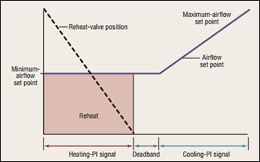
Source: Taylor Engineering
Dual Maximum:
Raises the supply air temperature (SAT) as the first stage of heating, and increases the airflow to the zone as the second stage of heating.
1. The first stage of heating consists of modulating the zone supply air temperature setpoint up to a maximum setpoint no larger than 95°F while the airflow is maintained at the dead band flow rate.
2. The second stage of heating consists of modulating the airflow rate from the dead band flow rate up to the heating maximum flow rate (50 percent of design flow rate).
Figure 10: Dual Maximum Control Sequence
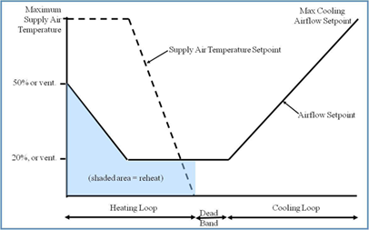
Source: Taylor Engineering
Units
List:
•Single maximum
•Dual maximum
Input Restrictions
Fixed at single maximum if control system type is not direct digital control (DDC) control to the zone level
Standard Design
Dual maximum
For healthcare facilities, same as the Proposed Design.
Standard Design:
Existing Buildings