
RA3.5 is a procedure for verifying the quality of insulation installation and air leakage control used in low-rise residential buildings. This procedure is to be followed by the insulation installer and a qualified Home Energy Rating System (HERS) rater must verify its conformance for meeting the requirements of Sections 150.1(c), and 110.7 of the Standards.
The procedure applies to wood and metal construction of framed and non-framed envelope assemblies. Framed assemblies include wall stud cavities, roof/ceiling assemblies, and floors typically insulated with: (1) batts of mineral fiber and mineral wool; (2) loose-fill materials of mineral fiber, mineral wool, and cellulose; (3) spray polyurethane foam; and, (4) rigid board sheathing materials. Non-framed assemblies include wall, roof/ceiling, and floors constructed of structural insulated panels and insulated concrete forms.
Note 1: For newly constructed buildings, this procedure applies to the entire thermal envelope of the building. In many instances, residential homes will use several types of insulation material, even in the same framed assembly. Each insulation material and the integrity of air leakage control for the building's entire thermal envelope must be verified by the HERS rater for the home to comply with the Standards.
Note 2: Structural bracing, tie-downs, and framing of steel or specialized framing used to meet structural requirements of the California Building Code (CBC) are allowed. These areas shall be called out on the building plans with diagrams and/or specific design drawings indicating the R-value amount and fastening method to be used. All structural framing areas shall be insulated in a manner that resists thermal bridging from the outside to the inside of the assembly separating conditioned from unconditioned space. The insulation and air barrier integrity shall be verified by the HERS rater.
|
Continuous Air Barrier
|
A combination of interconnected materials and assemblies joined and sealed together to provide a continuous barrier to air leakage through the building envelope separating conditioned from unconditioned space, or adjoining conditioned spaces of different occupancies or uses. An air barrier is required in all thermal envelope assemblies to limit air movement between unconditioned/outside spaces and conditioned/inside spaces and must meet one of the following: 1. Using individual materials that have an air permeance not exceeding 0.004cfm/ft2 under a pressure differential of 0.3in. w.g. (1.57psf) (0.02 L/s.m2 at 75 pa) when tested in accordance with ASTM E2178; or 2. Using assemblies of materials and components that have an average air leakage not to exceed 0.04 cfm/ft2 under a pressure differential of 0.3 in. w.g (1.57psf) (0.2 L/s.m2 at 75 pa) when tested in accordance with ASTM E2357, ASTM E1677, ASTM E1680 or ASTM E283; or 3. Testing the completed building and demonstrating that the air leakage rate of the building envelope does not exceed 0.40 cfm/ft2 at a pressure differential of 0.3 in w.g. (1.57 psf) (2.0 L/s.m2 at 75 pa) in accordance with ASTM E779 or an equivalent approved method. Individual materials and assemblies of materials that can demonstrate compliance with the air barrier testing requirements must be installed according to the manufacturer's instructions and a HERS rater shall verify the integrity of the installation. Below are example materials meeting the air permeance testing performance levels of 1 above. Manufacturers of these and other product types must provide a specification or product data sheet showing compliance to the ASTM testing requirements to be considered as an air barrier. -- Plywood – minimum 3/8 inch -- Oriented strand board – minimum. 3/8 inches -- Extruded polystyrene insulation board – minimum. ½ inch -- Foil-back polyisocyanurate insulation board – minimum. ½ inch -- Extruded polystyrene insulation board – minimum ½ inch -- Foil backed urethane foam insulation (1 inch) -- Closed cell spray polyurethane foam with a minimum density of 2.0 pcf and a minimum thickness of 2.0 inches -- Open cell spray polyurethane foam with a minimum density of 0.4 to1.5 pcf and a minimum thickness of 5½ inches -- Exterior or interior gypsum board - minimum 1/2 inch -- Cement board - minimum 1/2 inch -- Built up roofing membrane -- Modified bituminous roof membrane -- Particleboard-minimum1/2 inch -- Fully adhered single-ply roof membrane -- Portland cement/sand parge, or gypsum plaster minimum 5/8 inch -- Cast-in-place and precast concrete. -- Fully grouted uninsulated and insulated concrete block masonry -- Sheet steel or aluminum |
|
Air-tight |
Limiting the passage of air either in or out of the building envelope. Note: Thermal envelope assemblies (such as wall assemblies) shall be built to minimize air movement. Air movement brings unconditioned air and moisture through or into the assembly. For these procedures, air-tight shall be defined as an assembly or air barrier with all openings caulked, or sealed with minimally expansive foam, or taping/sealing of adjoining surfaces of air barrier materials and assemblies. |
|
Compression |
The improper placement of insulation in an assembly that results in an installation less than the product's nominal thickness. Batt insulation should be “lofted” and loose-fill and spray foam material properly field applied to the manufacturer’s specified density to achieve its full R-value. Limited compression is allowed at plumbing, vents, and other obstructions and in cavities of non-standard framing. Compression of insulation in these situations is limited to no more than 30% of its' nominal thickness. |
|
Delaminated |
Separation of the insulation's full thickness to facilitate it’s installation around or between obstructions. Batt and blanket insulation are often split or delaminated to fit around electrical wires and plumbing runs through a wall cavity. to prevent voids, or compression of the insulation. The delamination must ensure that the full thickness of the insulation is installed between the obstruction and the finish material covering the framing. For example, an electrical wire located one-third of the distance from the front of the cavity should have batt insulation delaminated so that two-thirds of the batt is installed towards the outside wall surface and one-third is installed towards the inside wall surface from the wire. |
|
Draft Stops
|
A material, device or construction installed to prevent the movement of air within open spaces of concealed areas of building components, such as crawl spaces, floor/ceiling assemblies, wall assemblies, roof/ceiling assemblies and attics. Note: Draft stops are important components of the air barrier and shall be air-tight. Fire blocks constructed of porous insulation materials cannot serve as draft stops since they are not air tight. |
|
Friction Fit |
A
means of installing insulation within the framed cavity without the use of
mechanical fasteners such that the material's full thickness in all
directions is sufficient to keep the material in its intended
position. In standard framing dimensions of 2x4 and 2x6 @ 16" oc and
24" oc batt and blanket insulation materials have enough side-to-side
frictional force to hold the insulation in place without any other means
of attachment. |
|
Gaps |
Uninsulated areas at the edge of insulation where insulation is not in contact with framing members or other materials at the edge of the insulation. Gaps occur when insulation length and width is too short for the cavity. Gaps in insulation are avoidable and are not permitted. |
|
Hard Covers |
Building materials, such as plywood or gypboard, which become part of the ceiling air barrier. Note: Hard covers shall be installed above areas where there is a drop ceiling. For example, a home with 10ft ceilings may have an entry closet with a ceiling lowered to 8ft. In this case, a hard cover is installed at the 10ft level above the entry closet. Hard covers become part of the ceiling air barrier and shall be air-tight. |
|
Inset Stapling |
A method of attaching faced batt or blanket insulation to wood framing, where the flange of the insulation facing is pushed inside the face of the framing member and stapled This method causes a void between the insulation and the air barrier. In windy areas installers often staple the flanges of faced batts to the sides of the stud to assure that the insulation remains in place until covered with drywall, particularly on the wall between the house and the garage where there isn't any exterior sheathing to help keep the insulation in place. The void created by the flange inset shall not extend more than two inches from the stud on each side. |
|
Insulation Types--Framed Assemblies |
There are four basic types of insulation, or insulation "systems", installed in residential buildings and their use varies based on the design and type of construction: 1. Batt and Blanket: Batt and blanket insulation is made of mineral fiber and mineral wool -- either processed fiberglass, rock or slag wool -- and is used to insulate below floors, above ceilings, below roofs, and within walls. 2. Loose-fill: Loose-fill insulation includes loose fibers or fiber pellets that are blown into building cavities or attics using special equipment. Loose-fill insulations typically are produced using mineral fiber, mineral wool, or cellulose. They are installed in walls, floors, attics and below roofs using a dry-pack process or a moist-spray technique, and may include a netting material. 3. Rigid Board: Rigid board insulation sheathing is made from fiberglass, expanded polystyrene (EPS), extruded polystyrene (XPS), polyisocyanurate (PIR), or polyurethane (PUR). This type of insulation is used for above roof decks, exterior walls, cathedral ceilings, basement walls, as perimeter insulation at concrete slab edges, and to insulate special framing situations such as window and door headers, and around metal seismic bracing. Rigid board insulation may also be integral to exterior siding materials. 4. Spray Polyurethane Foam (SPF): A two-part liquid foamed plastic (such as polyurethane or modified urethane) material formed by the reaction of an isocyanurate and a polyol that uses a blowing agent to develop a cellular structure when spray applied onto a substrate. SPF insulation is a two-component reactive system mixed at a spray gun or a single-component system that cures by exposure to humidity. The liquid is sprayed through a nozzle into wall, roof/ceiling, and floor cavities. SPF insulation can be formulated to have specific physical properties (i.e., density, compressive strength, fire resistance and R-value). There are two types of SPF insulation: a. Low Density Open-Cell SPF (ocSPF) Insulation: A spray applied polyurethane foam insulation having an open cellular structure resulting in an installed nominal density of 0.4 to 1.5 pounds per cubic foot (pcf). b. Medium Density Closed-Cell SPF (ccSPF) Insulation: A spray applied polyurethane foam insulation having a closed cellular structure resulting in an installed nominal density of greater than 1.5 to less than 2.5 pounds per cubic foot (pcf). |
|
Insulation Types--Non-framed Assemblies |
There are two basic types of insulation used and their use varies based on the design and type of construction: 1. Structural Insulated Panel (SIP): A composite building material consisting of an insulating layer of rigid polymer foam sandwiched between two layers of structural board. The board can be sheet metal, plywood, cement or oriented strand board (OSB) and the foam is either expanded polystyrene foam (EPS), extruded polystyrene foam (XPS) or polyurethane (PUR) foam . SIPs combine several components of conventional building, such as studs and joists, insulation, vapor barrier and air barrier. They can be used for many different applications, such as exterior walls, roofs, floors, and foundation systems. 2. Insulated Concrete Form (ICF): A system of formwork for concrete that stays in place as permanent building insulation and is used for cast-in-place, reinforced above and below-grade concrete walls, floors, and roofs. ICFs are interlocking modular units that can be dry-stacked (without mortar) and filled with concrete as a single concrete masonry unit (CMU). ICFs lock together externally and have internal metal or plastic ties to hold the outer layer(s) of insulation to create a concrete form for the structural walls, roof/ceilings, or floors of a building. ICFs are manufactured from several materials including: expanded and extruded polystyrene foam, polyurethane foam, cement-bonded wood fiber, and cement-bonded polystyrene beads. |
|
Minimally Expansive Foam Sealing Material |
A single-component polyurethane foam system typically formulated in a handheld can or portable container to seal and fill construction gaps and crevasses, holes, and cracks without distorting adjacent framing. These materials are not used for insulation purposes, rather as agents for air sealing of gaps and crevasses that are too small to be insulated. |
|
Net Free-Area |
The net free-area of a vent cover is equal to the total vent opening less the interference to airflow caused by a screen or louver used for ventilation. Screened or louvered vent opening covers are typically marked by the manufacturer with the "net free-area." For example a 22.5 in. by 3.5 in. eave vent screen with a total area of 78.75 square inches may have a net free-area of only 45 square inches. |
|
Non-Standard Framing |
Standard framing consists of installation of framing members spaced at regular intervals (16" or 24" on center), where batt insulation products can be installed to the full dimensional width of the cavity between framing members. Non-Standard framing may include multiple framing members, framing members at unusual spacing, additional blocking within cavity, structural columns or beams, or metal structural connections that alter the cavity depth or width. |
|
Voids & Air Spaces |
An uninsulated space within an enclosed building assembly created where the assembly has been insulated by partial filling of the framed cavity. The partial fill results in an air space (void) between the insulation surface and the assembly’s exterior or interior layers which form the assembly’s air barrier. |
These procedures detail the installation and inspection protocols necessary to qualify for Quality Insulation Installation (QII) of batt and blanket insulation. These procedures must be field verified before the building construction permit is finalized.
These procedures are to be followed by the insulation installer and a qualified Home Energy Rating System (HERS) rater must verify its conformance to meet the requirements of Sections 150.1(c), and 110.7 of the Standards.
RA3.5.3.1 Thermal Specification
This insulation type is manufactured in different widths, lengths, and thicknesses and is available with or without a facing. Faced batts and blanket insulation material are also available with or without an attachment flange. Specific product R-values are readily available from the manufacturer for the specific materials being installed and the R-value of the product is marked on the face of the product (faced or unfaced material). The installed insulation must meet the R-value stated on the compliance documentation.
(a) Materials shall comply with, and be installed in conformance with, all applicable building codes for building. California Building Code (including, but not limited to, California Electric Code Section 719) and installed to meet all applicable fire codes.
(b) Materials shall meet California Quality Standards for Insulating Material, Title 24, Part 12, Chapter 4, Article 3, 'listed in the California Department of Consumer Affairs Consumer Guide and Directory of Certified Insulating Materials.
(c) Materials shall comply with flame spread rating and smoke density requirements of Chapter 26 and Section 706 of the Title 24, Part 2: all installations with exposed facings must use fire retardant facings which have been tested and certified not to exceed a flame spread index (FSI) of 25 and a smoke development index (SDI) of 450. Insulation facings that do not touch a ceiling, wall, or floor surface, and faced batts on the undersides of roofs with an air space between the ceiling and facing are considered exposed applications.
(d) Materials shall be installed according to manufacturer specifications and instructions.
(e) Batt and blanket insulation shall be correctly sized to fit snugly at the sides and ends.
(f) Batt and blanket insulation shall be installed so that they will be in contact with the air barrier.
(g) Where necessary, batt and blanket insulation shall be cut to fit properly - there shall be no gaps, nor shall the insulation be doubled-over or compressed.
(h) When batt and blanket insulation are cut to fit a non-standard cavity, they shall be snuggly fitted to fill the cavity without compression.
(i) Batt and blanket insulation shall be cut to butt-fit around wiring and plumbing, or be split (delaminated) so that one layer can fit behind the wiring or plumbing, and one layer fit in front.
The HERS rater shall verify the installed thickness of insulation in all assemblies and locations on walls, roof/ceilings, and floors, and to ensure that insulation levels and installation integrity meet the R-value specified on the Certificate of Compliance, and all other required compliance documentation.
All provisions of Residential Appendix RA2 shall be met. All Insulation Certificates of Installation signed by the insulation installer shall be provided stating the installation is consistent with the Certificate of Compliance, plans and specifications for which the building permit was issued. The insulation installer shall complete all applicable sections of the Certificate of Installation form and attach a product specification or data sheet for every insulation material used.
All provisions of Residential Appendix RA2 shall be met. The Insulation Certificate of Installation, with insulation material labels or specification/data sheets attached, signed by the insulation installer, shall be available on the building site for each of the HERS rater's verification inspections. Note: The HERS rater cannot verify compliance credit without these completed forms.
RA3.5.3.2 Wall Insulation
(a) Wall stud cavities shall be caulked, foamed or otherwise sealed to provide a substantially air-tight envelope to the outdoors, attic, garage and crawl space. All plumbing and wiring penetrations through the top and bottom plates and electrical boxes that penetrate the sheathing shall be sealed. All gaps in the air barrier shall be caulked, taped, or sealed with minimally expansive foam.
(b) Bottom plates of framed and non-framed assemblies shall be sealed to the ground subfloor or slab, and above ground subfloor.
(c) Insulation shall uniformly fill the cavity side-to-side, top-to-bottom, and front-to-back.
(d) Batt insulation shall fill the cavity by friction fitting, inset or face stapling of flanges of faced batts, or by other support methods as necessary.
(e) Batt and blanket insulation shall be installed to fill the cavity and be in contact with the sheathing on the back and the wallboard on the front - no gaps or voids.
Exception to RA3.5.3.2(e): Batt insulation with flanges that are inset stapled to the side of the stud, the surface of the batt facing the occupied space must be flush with the face of the cavity (or protrude beyond) except for the portions of the batt that are less than two inches from the side of the stud.
(f) When batt and blanket insulation are cut to fit a non-standard framing, they shall be snuggly fitted to fill the cavity with limited compression.
(g) Batt insulation shall be cut to butt-fit around wiring and plumbing, or be split (delaminated) so that one layer can be fit behind the wiring or plumbing, and one layer fit in front. The layers must be proportional to the obstruction's position in the cavity to avoid compression and voids.
(a) Non-standard width cavities shall be filled with insulation to snuggly fit into the space, or with minimally expansive foam sealing material.
(b) Narrow spaces less than 1 inch in width at windows and door jambs, shall be filled with minimally expansive foam sealing. In cases where the manufacturer's warranty would be void if minimally expansive foam is used to seal the gap between the window frame or door jamb, the cavity must be airtight and batt insulation cut to width and snuggly fitted (with limited compression) in the space.
(c) Narrow spaces less than 2 inches in width, such as between studs at building corners, and at the intersection of interior partition walls to exterior walls, shall be filled with insulation snuggly fitted in the space, or with minimally expansive foam sealing.
(a) Hard to access wall stud cavities, such as corner channels, wall intersections, and behind tub/shower enclosures shall be insulated to the proper R-value. In most cases this can only be completed prior to the installation of the tub/shower enclosure, the exterior sheathing, or the exterior stucco lath.
(b) An air barrier shall be installed on the inside of the exterior wall(s) directly adjacent to the tub/shower enclosure.
(a) Insulation shall be delaminated or cut to fit around wiring, plumbing, vents, and other obstructions with limited compression. Compression of insulation in these situations is limited to ≤ 30% of its nominal thickness.
(b) Insulation shall be placed between the sheathing and the rear of electrical boxes and other obstructions that are not as deep as the cavity (i.e. communications boxes, medicine cabinets).
(c) In cold climates, where water pipes may freeze (such as Climate Zones 2, 11-14 and 16) pipes shall have at least 1/2 of the insulation between the water pipe and towards the outside surface of the exterior wall. As much insulation as possible shall be placed between the pipe and the outside (without compression), and remaining insulation shall be placed between the pipe and the interior assembly material.
(a) All rim-joists shall be insulated to the same R-value as the adjacent walls.
(b) The insulation shall be installed without gaps, voids, or compression.
(b) The insulation shall be installed without gaps or compression.
(c) Steel-framed kneewalls and skylight shafts, external surfaces of steel studs shall meet or exceed the mandatory minimum insulation requirements and be covered with continuous insulation unless otherwise specified on the Certificate of Compliance using correct U-factors from Joint Appendix JA4, Table 4.3.4 (or U-factors approved by the Commission Executive Director).
(d) The backside of air permeable insulation exposed to the unconditioned attic space shall be completely covered with a continuous air barrier.
(e) The house side of the insulation shall be in contact with the drywall or other wall finish.
(f) The insulation shall be supported so that it will not fall down by either friction fitting to the framing, inset or face stapling of flanges, or using other support such as netting.
(g) Insulation for all kneewall and skylight shafts shall be completely enclosed by vertical and horizontal framing, including horizontal plates at top and bottom of the insulation.
Walls of interior closets for HVAC and/or water heating equipment, which require combustion air venting, shall be insulated to at least the same R-value as other demising walls (i.e., walls separating conditioned space and attached garage), or as specified on the Certificate of Compliance.
(a) Insulation shall fill the entire cavity; or, an additional air barrier shall be installed inside the double wall or bump-out and in contact with the insulation so that the insulation fills the cavity formed with the additional air barrier.
(b) Entire double walls and framed bump-outs shall be air-tight.
(a) Framing and bracing used for structural purposes shall be identified on plan documents with diagrams and/or design drawings.
(b) Insulation shall be installed in a manner that minimizes heat loss/gain due to thermal bridging through the structural framing assembly.
(c) Insulation shall be applied to fully enclose and/or adhere to all sides and ends of structural assembly framing that separate conditioned from unconditioned space.
(d) The structural portions of assemblies shall be air-tight.
(a) All single-member window and door headers shall be insulated to a minimum of R-3 for a 2x4 framing, or equivalent width, and a minimum of R-5 for all other assemblies. Insulation is to be placed between the interior face of the header and inside surface of the interior wall finish.
(b) No header insulation is required for single-member headers that are the same width as the wall, provided that the entire wall has at least R-2 insulation.
(a) In unvented attics, where insulation is applied directly to the underside of the roof deck, framing for gable ends that separate the unvented attic from the exterior or unconditioned space shall be insulated to meet or exceed the wall R-value of the adjacent exterior wall construction as specified on the Certificate of Compliance.
(b) The backside of air permeable insulation exposed to the unconditioned attic space shall be completely covered with a continuous air barrier.
RA3.5.3.3 Roof/Ceilings
(a) Batt and blanket insulation shall be correctly sized to fit snugly at the sides and ends.
(b) Batt and blanket insulation shall be installed to be in contact with the air barrier.
(c) Where necessary, batt and blanket insulation shall be cut to fit properly - there shall be no gaps, nor shall the insulation be doubled-over or compressed.
(d) When batt and blanket insulation are cut to fit a non-standard cavity, they shall be snuggly fitted to fill the cavity with limited compression.
(e) Batt and blanket insulation shall be cut to butt-fit around wiring and plumbing, or be split (delaminated) so that one layer can fit behind the wiring or plumbing, and one layer fit in front.
(f) Batt and blanket insulation that is thicker than the framing depth shall be installed so that the insulation expands to touch adjacent insulation over each framing member.
(g) Hard covers or draft stops shall be placed over all drop ceiling areas and interior wall cavities to keep insulation in place and stop air movement. If hard covers or draft stops are missing or incomplete, they shall be completed before insulation is installed.
(h) Baffles shall be placed at eaves or soffit vents of vented attics to keep insulation from blocking eave ventilation and prevent air movement under the insulation. The required net free-ventilation shall be maintained.
(i) All recessed light fixtures that penetrate the ceiling shall be listed for zero clearance insulation contact (IC), have a label that certifies it as airtight with leakage less than 2.0 cfm @ 75 Pa when tested to ASTM E283, and shall be sealed with a gasket or caulk between the light's housing and the ceiling.
(j) Insulation shall cover all recessed lighting fixtures. Fixtures that are not rated for insulation contact (IC), and air-tight, shall be removed and/or replaced.
(k) Facings and insulation shall be kept away from combustion appliance flues in accordance with flue manufacturer's installation instructions or labels on the flue.
(a) In vented rafter ceilings, an air space shall be maintained between the insulation and roof sheathing as specified by California Building Code, Sections 1203.2 and R806.3, or as specified by the local building department.
(b) Insulation installed in unvented rafter ceilings or to the underside of unvented roofs with an attic below shall have an R-value conforming to compliance documentation and the air barrier shall be uniform across the transition of roof to wall. The insulation shall be in contact with the air barrier.
(a) Batt and blanket insulation shall be placed below all platforms or cat-walks used for HVAC equipment installation and access.
(b) Batt and blanket insulation shall be installed so that they will be in contact with the air barrier.
(c) Batt and blanket insulation shall be installed under HVAC platform to the full depth and rated R-value as specified on the Certificate of Compliance, without gaps or compression. If necessary, HVAC platform shall be raised to accommodate ceiling insulation.
Permanently attach rigid board insulation or batt or blanket insulation with the appropriate R-value to the access door using adhesive or mechanical fastener. The bottom of the attic access shall be gasketed to prevent air leakage of conditioned air to the unconditioned attic.
(a) Below roof deck insulation consisting of batts that nominally fill the cavity space between roof framing members shall be stapled, or supported with cabling, tension rods, or other support measures which maintain the batt uniformly against the roof deck with limited compression. Batts with facing directed to the attic space shall be face stapled. Inset stapling of underside batts is not allowed. Batts supported with cabling, tensions rods, or other methods supporting the batt from below shall be supported at intervals less than or equal to 16", and no further than 8" from the end of the batt. Batts that are directly stapled through the insulation material to the roof deck should maintain the batt uniformly against the roof deck with limited compression.
(b) When the batt thickness nominally exceeds the depth of the roof framing members, full-width batts must be used and the batt shall be secured as described in (a). Full depth insulation coverage at the bottom of the roof framing member is not required as part of the QII inspection process.
(c) For vented attics, below deck batt or blanket insulation shall be installed in a manner that does not obstruct eave, ridge, or eyebrow vents to allow for adequate attic ventilation. The required net free ventilation area of all eave and roof vents shall be maintained. Eave vent baffles shall be installed to prevent air movement under or into the batt.
RA3.5.3.4 Raised Floors
(a) Batt and blanket insulation shall be correctly sized to fit snugly at the sides and ends.
(b) Batt and blanket insulation shall be cut to fit properly without gaps. Insulation shall not be doubled-over or compressed.
(c) Batt and blanket insulation shall be in contact with the air barrier - usually the subfloor.
(a) Batt and blanket insulation shall be correctly sized to fit snugly at the sides and ends, but not be so large as to buckle.
(b) Batt and blanket insulation shall be cut to fit properly without gaps. Insulation shall not be doubled-over or compressed.
(c) Batt and blanket insulation shall be in contact with the air barrier - usually the subfloor.
(d) On floors that are over garages, or where there is an air space between the insulation and the subfloor, the rim joist shall be insulated.
(e) Batt and blanket insulation shall be cut to butt-fit around wiring and plumbing, or be split (delaminated) so that one layer can fit behind the wiring or plumbing, and one layer fit in front.
(f) Faced batts or blankets shall be placed toward the living space and be in contact with the underside of the floor sheathing. Continuous support shall be provided to keep the facing in contact with the floor sheathing. The insulation shall be properly supported by stapling of flanges, netting or other method approved by the manufacturer for the product.
(g) Batt and blanket insulation shall be properly supported to avoid gaps, voids, and compression.
The separation between conditioned space (house) and the garage shall be insulated to create a continuous thermal barrier. All rim and band joists adjoining conditioned space shall be air tight and insulated.
Figure RA3.5-1 Homes with Conditioned Space Over Garage – Batt and Blanket Insulation
The band joist where the garage transitions to an attic above conditioned space shall have an air barrier installed in contact with the edge of the attic insulation.

Figure RA3.5-2 Homes with No Conditioned Space Over Garage – Batt and Blanket Insulation
These procedures detail the installation and inspection protocols necessary to qualify for Quality Insulation Installation (QII) of loose-fill insulation. These procedures must be field verified before the building construction permit is finalized.
These procedures are to be followed by the insulation installer and a qualified Home Energy System (HERS) rater must verify conformance to meet the requirements of Sections 150.1(c) and 110.7 of the Standards.
RA3.5.4.1 Thermal Specification
This insulation type is manufactured to be blown or sprayed into framed cavity walls, floors, and ceilings. It is installed with or without a net depending on the loose-fill type or in special installations where netting is required, such as below a roof deck or under floors. Its overall R-value is dependent on the installed density and installed thickness. Specific product R-values are readily available from the manufacturer for the specific materials being installed. R-value and coverage chart of the product is typically marked on the bag which the insulation was drawn from and from the manufacturer's product data sheet or product specification information. The installed insulation must meet the R-value stated on the compliance documentation.
(a) Materials shall comply with, and be installed in conformance with, all applicable building codes for building. California Building Code (including, but not limited to, California Electric Code Section 719) and installed to meet all applicable fire codes.
(b) Materials shall meet California Quality Standards for Insulating Material, Title 24, Part 12, Chapter 4, Article 3, listed in the California Department of Consumer Affairs Consumer Guide and Directory of Certified Insulating Materials.
(c) Materials shall comply with flame spread rating and smoke density requirements of Chapter 26 and Section 706 of the Title 24, Part 2: all installations with exposed facings must use fire retardant facings which have been tested and certified not to exceed a flame spread index (FSI) of 25 and a smoke development index (SDI) of 450. Insulation facings that do not touch a ceiling, wall, or floor surface, and faced batts on the undersides of roofs with an air space between the ceiling and facing are considered exposed applications.
(d) Materials shall be installed according to manufacturer specifications and instructions.
(e) Hard covers or draft stops shall be placed over all drop ceiling areas and interior wall cavities to keep insulation in place and stop air movement. If hard covers or draft stops are missing or incomplete, they shall be completed before insulation is installed.
(f) Required eave ventilation shall not be obstructed - the net free-ventilation area of the eave vent shall be maintained.
(g) Eave vent baffles shall be installed to prevent air movement under or into the batt.
(h) Insulation shall cover all recessed lighting fixtures. If the fixtures are not rated for insulation contact (IC) and air tight, the fixtures shall be replaced.
(i) All recessed light fixtures that penetrate the ceiling shall be listed for zero clearance insulation contact (IC), have a label that certifies it as airtight with leakage less than 2.0 cfm @ 75 Pa when tested to ASTM E283, and shall be sealed with a gasket or caulk between the light's housing and the ceiling.
(j) Loose-fill insulation shall be must completely fill the framed cavity.
(k) Loose-fill insulation shall be installed so that they will be in contact with the air barrier.
The HERS rater shall measure the installed thickness and density of insulation in at least 6 random locations on walls, roof/ceilings and floors (i.e., 6 measurements per opaque surface type: wall, roof/ceiling or floor) to ensure minimum thickness levels and the installed density meets the R-value specified on the Certificate of Compliance, and all other required compliance documentation. For walls, measurement areas shall include low and high areas of the insulated assembly and the HERS rater shall verify density measurements are consistent with the manufacturer's coverage chart.
(a) All provisions of Residential Appendix RA2 shall be met. All Insulation Certificates of Installation signed by the insulation installer shall be provided stating the installation is consistent with the Certificate of Compliance, plans and specifications for which the building permit was issued. The insulation installer shall complete all applicable sections of the Certificate of Installation form and attach a bag label or a manufacturer's coverage chart for every different type of loose-fill insulation material used.
(b) For loose-fill insulation, compliance information shall include the minimum installed weight-per-square-foot (or the minimum weight per cubic foot) consistent with the manufacturer's labeled installed-design-density for the desired R-value, and the number of inches required to achieve the desired R-value.
All provisions of Residential Appendix RA2 shall be met. The Insulation Certificate of Installation, with insulation material bag labels or coverage charts attached, signed by the insulation installer, shall be available on the building site for each of the HERS rater's verification inspections. Note: The HERS rater cannot verify compliance credit without these completed forms.
RA3.5.4.2 Wall Insulation
(a) Wall stud cavities shall be caulked, foamed or otherwise sealed to provide a substantially air-tight envelope to the outdoors, attic, garage and crawl space. Special attention shall be paid to plumbing and wiring penetrations through the top plates, electrical boxes that penetrate the sheathing, and the sheathing seal to the bottom plate. All gaps in the air barrier shall be caulked, or sealed with expansive or minimally expansive foam.
(b) Bottom plates of framed and non-framed assemblies shall be sealed to the ground subfloor or slab, and above ground subfloor.
(c) Insulation shall uniformly fill the cavity side-to-side, top-to-bottom, and front-to-back.
(d) Loose fill insulation shall be installed to fill the cavity and be in contact with the sheathing on the back and the wallboard on the front - no gaps or voids.
(e) Loose fill wall insulation shall be installed to fit around wiring, plumbing, and other obstructions.
(f) Non-standard-width cavities shall be filled with insulation fitted into the space without excessive compression.
(g) The installer shall certify on the Certificate of Installation forms that the manufacturer's minimum weight-per-square-foot requirement has been met.
(a) Non-standard width cavities shall be filled with insulation to snuggly fit into the space, or with minimally expansive foam sealing material.
(b) Narrow spaces less than 1 inch in width at windows and door jambs, shall be filled with minimally expansive foam sealing. In cases where the manufacturer's warranty would be void if minimally expanding foam is used to seal the gap between the window frame or door jamb, the cavity must be airtight and filled with insulation snuggly fitted (with limited compression) in the space.
(c) Narrow spaces less than 2 inches in width, such as between studs at building corners, and at the intersection of interior partition walls to exterior walls, shall be filled with insulation snuggly fitted in the space, or with minimally expansive foam sealing.
(a) Hard to access wall stud cavities, such as; corner channels, wall intersections, and behind tub/shower enclosures shall be insulated to the proper R-value. In most cases this can only be completed prior to the installation of the tub/shower enclosure, the exterior sheathing, or the exterior stucco lath.
(b) An air barrier shall be installed on the inside of the exterior wall(s) directly adjacent to the tub/shower enclosure.
(a) Insulation shall completely fill around wiring and plumbing without compression.
(b) Insulation shall fill between the sheathing and the rear of electrical boxes and phone boxes.
(c) In cold climates, where water pipes may freeze (such as Climate Zones 2, 11-14 and 16) pipes shall have at least 1/2 of the insulation between the water pipe and towards the outside surface of the exterior wall. As much insulation as possible shall be placed between the pipe and the outside (without compression), and remaining insulation shall be placed between the pipe and the interior assembly material.
(a) All rim-joists shall be insulated to the same R-value as the adjacent walls.
(b) The insulation shall be installed without gaps, voids, or excessive compression.
(a) Framing for kneewalls and skylight shafts that separate conditioned from unconditioned space shall be insulated to meet or exceed the wall R-value specified on the Certificate of Compliance, and all other required compliance documentation.
(b) The insulation shall be installed without gaps or compression.
(c) Steel-framed kneewalls and skylight shafts, shall meet or exceed the mandatory minimum insulation requirements and external surfaces of steel studs shall be covered with continuous insulation unless otherwise specified on the Certificate of Compliance using correct U-factors from Joint Appendix JA4, Table 4.3.4 (or U-factors approved by the Commission Executive Director).
(d) The backside of air permeable insulation exposed to the unconditioned attic space shall be completely covered with a continuous air barrier.
(e) The house side of the insulation shall be in contact with the drywall or other wall finish.
(f) The insulation shall be supported so that it will not fall down by using support such as netting.
(g) Insulation for all kneewall and skylight shafts shall be completely enclosed by vertical and horizontal framing, including horizontal plates at top and bottom of the insulation.
Walls of interior closets for HVAC and/or water heating equipment, which require combustion air venting, shall be insulated to at least the same R-value as other demising walls (i.e., walls separating conditioned space and attached garage), or as specified on the Certificate of Compliance.
(a) Insulation shall fill the entire cavity; or, an additional air barrier shall be installed inside the double wall or bump-out and in contact with the insulation so that the insulation fills the cavity formed with the additional air barrier.
(b) Entire double walls and framed bump-outs shall be air-tight.
(a) Framing and bracing used for structural purposes shall be identified on plan documents with diagrams and/or design drawings.
(b) Insulation shall be installed in a manner that restricts thermal bridging through the structural framing assembly.
(c) Insulation shall be applied to fully enclose and/or adhere to all sides and ends of structural assembly framing that separate conditioned from unconditioned space.
(d) The structural portions of assemblies shall be air-tight.
(a) All single-member window and door headers shall be insulated to a minimum of R-3 for a 2x4 framing, or equivalent width, and a minimum of R-5 for all other assemblies. Insulation is to be placed between the interior face of the header and inside surface of the interior wall finish.
(b) No header insulation is required for single-member headers that are the same width as the wall, provided that the entire wall has at least R-2 insulation.
(a) In unvented attics, where insulation is applied directly to the underside of the roof deck, framing for gable ends that separate the unvented attic from unconditioned space shall be insulated to meet or exceed the wall R-value of the adjacent exterior wall construction as specified on the Certificate of Compliance.
(b) The backside of air permeable insulation exposed to the unconditioned attic space shall be completely covered with a continuous air barrier.
RA3.5.4.3 Roof/Ceilings
(a) Hard covers or draft stops shall be placed over all drop ceiling areas and interior wall cavities to keep insulation in place and stop air movement. If hard covers or draft stops are missing or incomplete, they shall be completed before insulation is installed or the entire drop area shall be filled with loose-fill insulation level with the rest of the attic.
(b) Baffles shall be placed at eaves or soffit vents of vented attics to keep insulation from blocking eave ventilation and prevent air movement under or into the insulation. The required net free-ventilation shall be maintained.
(c) Attic rulers appropriate to the material shall be installed and evenly distributed throughout the attic to verify depth: one ruler for every 250 square feet and clearly readable from the attic access. Attic rulers shall be scaled to read inches of insulation and the R-value installed.
(d) Insulation shall be applied underneath and on both sides of obstructions such as cross-bracing and wiring.
(e) Insulation shall be applied all the way to the outer edge of the wall top plate.
(f) All recessed light fixtures that penetrate the ceiling shall be 'listed for zero clearance insulation contact (IC), have a label that certifies it as airtight with leakage less than 2.0 cfm @ 75 Pa when tested to ASTM E283, and shall be sealed with a gasket or caulk between the light's housing and the ceiling.
(g) Insulation shall cover recessed lighting fixtures. Fixtures that are not rated for insulation cover (IC), and air tight, shall be removed and/or replaced.
(h) Insulation shall be kept away from combustion appliance flues in accordance with flue manufacturer's installation instructions or labels on the flue.
(i) Insulation shall be blown to a uniform thickness throughout the attic with all areas meeting or exceeding the insulation manufacturer's minimum requirements for depth and weight-per-square-foot.
(j) The installer shall certify on the Certificate of Installation forms that the manufacturer's minimum weight-per-square-foot requirement has been met.
(k) The HERS rater shall verify that the manufacturer's minimum weight-per-square-foot requirement has been met for attics insulated with loose-fill insulation. Verification shall be determined using the methods of the Insulation Contractor’s Association of America (ICAA) Technical Bulletin #17 or #33 except that only one sample shall be taken in the area that appears to have the least amount of insulation. The rater shall record the weight-per-square-foot of the sample on the Certificate of Verification.
(l) The HERS rater shall verify that the manufacturer’s minimum insulation thickness has been installed. For cellulose insulation, this verification shall take into account the time that has elapsed since the insulation was installed. At the time of installation, the insulation shall be greater than or equal to the manufacturer’s minimum initial insulation thickness. If the HERS rater does not verify the insulation thickness at the time of installation, and if the insulation has been in place less than fourteen days, the insulation thickness shall be greater than the manufacturer’s minimum required thickness to achieve the given R-value at the time of installation, less 1/2 inch to account for settling. If the insulation has been in place for fourteen days or more, the insulation thickness shall be greater than or equal to the manufacturer’s minimum required settled thickness to achieve the given R-value.
(a) An air space shall be maintained between the insulation and roof sheathing as specified by California Building Code Sections 1203.2 and R806.2, or as specified by the local building department.
(b) Insulation installed in unvented rafter ceilings or to the underside of unvented roofs with an attic below shall have an R-value conforming to compliance documentation and the air barrier shall be uniform across the transition of roof to wall. The insulation shall be in contact with the air barrier.
(a) Loose-fill insulation shall be placed below any platform or cat-walk for HVAC equipment installation and access.
(b) Loose-fill insulation shall be installed so that it will be in contact with the air barrier.
(c) Loose-fill insulation shall be installed under HVAC platform to the full depth and rated R-value as specified on the Certificate of Compliance, without gaps or compression. If necessary, HVAC platform shall be raised to accommodate ceiling insulation.
Permanently attach rigid board insulation or batt or blanket insulation with the appropriate R-value to the access door using adhesive or mechanical fastener. The bottom of the attic access shall be gasketed to prevent air leakage of conditioned air to the unconditioned attic.
(a) Below roof deck loose-fill insulation shall be netted and installed per manufacturer's specifications.
(b) For vented attics, below deck loose-fill insulation shall be installed in a manner that does not obstruct soffit, eave, ridge or eyebrow vents to allow for adequate attic ventilation. Netting shall be installed in a manner that allows for the required net free area of soffit, eave, gable, and roof vents to be maintained after being filled. Eave vent baffles shall be installed to prevent air movement under or into the insulation.
(c) Netting shall be installed to seal around conduit, plumbing, roof penetrations and all other obstructions that penetrate the netting.
(d) Loose-fill insulation shall be installed uniformly in the netted cavity side-to-side, top-to-bottom, and front-to-back and be in continuous contact with the roof sheathing. Loose-fill insulation shall be installed to fit around wiring, conduit, plumbing, and other obstructions.
(e) The installer shall certify on the Certificate of Installation compliance documents that the manufacturer's minimum weight-per-square-foot requirement has been met.
(f) The HERS Rater shall verify that the manufacturer's minimum insulation thickness and specified R-value has been installed.
(g) The HERS Rater shall verify the minimum weight-per-square-foot requirement has been met. Verification shall be determined using manufacturer's recommended verification procedures. The HERS Rater shall record the weight-per-square-foot of the sample on the Certificate of Verification.
(h) Box netted installations are where netting is suspended from the top of roofing framing member, or top chord, to provide a fill depth that completely encloses the top chord, creating a uniform insulation layer of loose-fill insulation across the entire underside of the roof deck. For these installations, netted insulation cavity thickness shall be uniform and meet the minimum insulation thickness.
(i) For draped netted installations, where netting is attached directly to the bottom of the roof framing member, the HERS Rater shall verify that average insulation depth in the cavity meets the depth as specified by the Certificate of Compliance.
RA3.5.4.4 Raised Floors
(a) Loose-fill insulation shall be in contact with the air barrier - usually the subfloor.
(b) Loose-fill insulation shall completely fill around wiring and plumbing.
(c) Loose-fill insulation shall be properly supported where necessary to avoid sagging, gaps, voids, and compression.
(a) Loose-fill insulation shall be in contact with the air barrier - usually the subfloor.
(b) On floors that are over garages, or where there is an air space between the insulation and the subfloor, the rim joist shall be insulated.
(c) Loose-fill insulation shall completely fill around wiring and plumbing.
(d) Loose-fill insulation shall be properly supported to avoid sagging, gaps, voids, and compression.
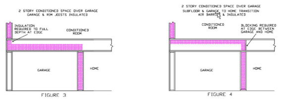
The separation between conditioned space (house) and the garage shall be insulated with fully supported loose-fill insulation to create a continuous thermal barrier. All rim and band joists adjoining conditioned space shall be air tight and insulated.
Figure RA3.5-3 Homes with Conditioned Space Over Garage – Loose Fill Insulation

The band joist where the garage transitions to an attic above conditioned space shall have an air barrier installed in contact with the edge of the attic insulation.
Figure RA3.5-4 Homes with No Conditioned Space over Garage – Loose Fill Insulation

These procedures detail the installation and inspection protocols necessary to qualify for Quality Insulation Installation (QII) of rigid board insulation sheathing material. These procedures must be field verified before the building construction permit is finalized.
These procedures are to be followed by the insulation installer and a qualified Home Energy Rating System (HERS) rater must verify its conformance for meeting the requirements of Sections 150.1(c) and 110.7 of the Standards.
RA3.5.5.1 Thermal Specification
This insulation type is manufactured of different materials and is in sheet or board form. Rigid board insulation materials are typically used on the exterior side of framed wall assemblies and over the top of exterior roof decks. These products also may be used for special situations in rafter spaces of cathedral ceilings, floors, at floor rim joists, and within or on the outside of window and door headers. This insulation type may also be integral to exterior siding materials. Rigid board insulation material most often is used in conjunction with other insulation materials installed within the framed cavity. The R-value is dependent on the type of material and its thickness. Specific product R-values are readily available from the manufacturer for the specific materials being installed. R-value of the product is typically marked on the product. The installed insulation must meet the R-value stated on the compliance documentation.
(a) Requirements for Walls, Ceilings and Floors Materials shall comply with, and be installed in conformance with, all applicable building codes for building. California Building Code (including, but not limited to, California Electric Code Section 719) and installed to meet all applicable fire codes.
(b) Materials shall meet California Quality Standards for Insulating Material, Title 24, Part 12, Chapter 4, Article 3, listed in the California Department of Consumer Affairs Consumer Guide and Directory of Certified Insulating Materials.
(c) Materials shall comply with flame spread rating and smoke density requirements of Chapter 26 and Section 706 of the Title 24, Part 2: all installations with exposed facings must use fire retardant facings which have been tested and certified not to exceed a flame spread index (FSI) of 25 and a smoke development index (SDI) of 450. Insulation facings that do not touch a ceiling, wall, or floor surface, and faced batts on the undersides of roofs with an air space between the ceiling and facing are considered exposed applications.
(d) Materials shall be installed according to manufacturer specifications and instructions.
(e) Rigid board insulation shall be attached according to the manufacturer's specifications.
(f) Rigid board insulation may be used as the air barrier provided it has been tested to conform to the air barrier performance conditions of the Standards.
The HERS raters shall verify the installed thickness of insulation in all assemblies and locations on walls, roof/ceilings, and floors, and to ensure that insulation levels and installation integrity meet the R-value specified on the Certificate of Compliance, and all other required compliance documentation.
All provisions of Residential Appendix RA2 shall be met. All Insulation Certificates of Installation signed by the insulation installer shall be provided stating the installation is consistent with the Certificate of Compliance, plans and specifications for which the building permit was issued. The insulation installer shall also complete the applicable sections of the Certificate of Installation form and attach a product specification or data sheet for every insulation material used.
All provisions of Residential Appendix RA2 shall be met. The Insulation Certificate of Installation, with insulation material labels or specification/data sheets attached, signed by the insulation installer, shall be available on the building site for each of the HERS rater's verification inspections. Note: The HERS rater cannot verify compliance credit without these completed forms.
RA3.5.5.2 Wall Insulation
(a) Wall stud cavities shall be caulked, foamed or otherwise sealed to provide a substantially air-tight envelope to the outdoors, attic, garage and crawl space. All plumbing and wiring penetrations through the top and bottom plates and electrical boxes that penetrate the sheathing shall be sealed. All gaps in the air barrier shall be caulked, or sealed with minimally expansive foam.
(b) Bottom plates of framed and non-framed assemblies shall be sealed to the ground subfloor or slab, and above ground subfloor.
(c) Installation shall uniformly fit across the plane of the wall and taping and/or caulking of all joints and seams of the insulation shall be maintained to be considered as the air barrier.
(a) Non-standard with cavities shall be filled with insulation to snuggly fit into the space, or with minimally expansive foam sealing material.
(b) Narrow spaces less than 1 inch in width at windows and door jambs, shall be filled with minimally expansive foam sealing material. In cases where the manufacturer's warranty would be void if minimally expanding foam is used to seal the gap between the window frame or door jamb, the cavity must be airtight and filled with insulation snuggly fitted in the space.
(c) Narrow spaces less than 2 inches in width, such as between studs at building corners and at the intersection of interior partition walls to exterior walls, shall be filled with insulation snuggly fitted in the space, or with minimally expansive foam sealing.
(a) Hard to access wall stud cavities, such as corner channels, wall intersections, and behind tub/shower enclosures shall be insulated to the proper R-value. In most cases, this can only be completed prior to the installation of the tub/shower enclosure, the exterior sheathing, or the exterior stucco lath.
(b) An air barrier shall be installed on the inside of the exterior wall(s) directly adjacent to the tub/shower enclosure.
(a) Penetrations and obstructions to the insulation shall be completely caulked and sealed.
(b) Insulation shall fill between the sheathing and the rear of electrical boxes and phone boxes.
(a) All rim-joists shall be insulated to the same R-value as the adjacent walls.
(b) The insulation shall be installed without gaps and voids.
(a) Framing for kneewalls and skylight shafts that separate conditioned from unconditioned space shall be insulated to meet or exceed the wall R-value specified on the Certificate of Compliance, and all other required compliance documentation.
(b) Steel-framed kneewalls and skylight shafts shall meet or exceed the mandatory minimum insulation requirements and external surfaces of steel studs shall be covered with continuous insulation unless otherwise specified on the Certificate of Compliance using correct U-factors from Joint Appendix JA4, Table 4.3.4 (or U-factors approved by the Commission Executive Director).
(c) The backside of air permeable insulation exposed to the unconditioned attic space shall be completely covered with a continuous air barrier.
Walls of interior closets for HVAC and/or water heating equipment which require combustion air venting, shall be insulated to at least the same R-value as other demising walls (i.e., walls separating conditioned space and attached garage), or as specified on the Certificate of Compliance.
(a) Insulation shall fill the entire cavity; or, an additional air barrier shall be installed inside the double wall or bump-out and in contact with the insulation so that the insulation fills the cavity formed with the additional air barrier.
(b) Entire double walls and framed bump-outs shall be air tight.
(a) Framing and bracing used for structural purposes shall be identified on plan documents with diagrams and/or design drawings.
(b) Insulation shall be installed in a manner that restricts thermal bridging through the structural framing assembly.
(c) Insulation shall be applied to fully enclose and/or adhere to all sides and ends of structural assembly framing that separate conditioned from unconditioned space.
(d) The structural portions of assemblies shall be air-tight.
(a) All single-member window and door headers shall be insulated to a minimum of R-3 for a 2x4 framing, or equivalent width, and a minimum of R-5 for all other assemblies. Insulation is to be placed between the interior face of the header and inside surface of the interior wall finish wall material.
(b) No header insulation is required for single-member headers that are the same width as the wall, provided that the entire wall has at least R-2 insulation.
(a) In unvented attics, where insulation is applied directly to the underside of the roof deck, framing for gable ends that separate the unvented attic from unconditioned space shall be insulated to meet or exceed the wall R-value of the adjacent exterior wall construction as specified on the Certificate of Compliance.
(b) The backside of air permeable insulation exposed to the unconditioned attic space shall be completely covered with a continuous air barrier.
RA3.5.5.3 Roof/Ceilings
(a) Baffles shall be placed at eaves or soffit vents of vented attics to keep insulation from blocking eave ventilation and prevent air movement under the insulation. The required net free-ventilation shall be maintained.
(b) Hard covers or draft stops shall be placed over all drop ceiling areas and interior wall cavities to keep insulation in place and stop air movement. If hard covers or draft stops are missing or incomplete, they shall be completed before insulation is installed.
(c) Rigid board insulation installed above the roof deck shall be applied to the outer edge of the plane of the wall top plate.
(d) Insulation shall cover all recessed lighting fixtures. If the fixtures are not rated for insulation contact (IC) and air tight, the fixtures shall be removed and/or replaced.
(e) All recessed light fixtures that penetrate the ceiling shall be listed for zero clearance insulation contact (IC), have a label that certifies it as airtight with air leakage less than 2.0 cfm @ 75 Pa when tested to ASTM E283, and shall be sealed with a gasket or caulk between the light's housing and the ceiling.
(a) An air space shall be maintained between the insulation and roof sheathing as specified by California Building Code Section 1203.2 and R806.2, or as specified by the local building department.
(b) Insulation installed in unvented rafter ceilings or to the underside of unvented roofs with an attic below shall have an R-value conforming to compliance documentation and the air barrier shall be uniform across the transition of roof to wall. The insulation shall be in contact with the air barrier.
Insulation shall be placed below any platform or cat-walk for HVAC equipment installation and access.
Permanently attach rigid board insulation or batt or blanket insulation with the appropriate R-value to the access door using adhesive or mechanical fastener. The bottom of the attic access shall be gasketed to prevent air leakage of conditioned air to the unconditioned attic.
RA3.5.5.4 Raised Floors
Rigid board insulation shall be in contact with the air barrier - usually the subfloor.
(a) Rigid board insulation shall be in contact with the air barrier - usually the subfloor.
(b) On floors that are over garages, or where there is an air space between the insulation and the subfloor, the rim joist shall be insulated.
The separation between conditioned space (house) and the garage shall be insulated with fully supported rigid board insulation to create a continuous thermal barrier. All rim and band joists adjoining conditioned space shall be air tight and insulated.
Figure RA3.5-5 Homes with Conditioned Space Over Garage – Rigid Board Insulation
The band joist where the garage transitions to an attic above conditioned space shall have an air barrier installed in contact with the edge of the attic insulation.
Figure RA3.5-6 Homes with No Conditioned Space Over Garage – Rigid Board Insulation

These procedures detail the installation and inspection protocols necessary to qualify for Quality Insulation Installation (QII) of spray polyurethane foam (SPF) insulation. These procedures must be field verified before the building construction permit is finalized.
These procedures are to be followed by the insulation installer and a qualified Home Energy Rating System (HERS) rater must verify its conformance for meeting the requirements of Sections 150.1(c) and 110.7 of the Standards.
These procedures apply to two types of SPF used as building insulation: medium-density closed cell SPF (ccSPF) and low-density open cell SPF (ocSPF). Most often, the same procedures will apply to both ccSPF and ocSPF. However, in some construction situations the procedures will be different.
NOTE: SPF insulation shall be field verified using these procedures whenever R-values other than the default R-value per inch are used for compliance (see "R-value" in sections RA3.5.6.1.1 and RA3.5.6.1.2 below).
RA3.5.6.1 Thermal Specification
A spray applied polyurethane foam insulation having a closed cellular structure resulting in an installed nominal density of 1.5 to less than 2.5 pounds per cubic foot (pcf).
R-value: The total R-value shall be calculated based on the nominal required thickness of the insulation multiplied by a thermal resistivity of 5.8 per inch. The R-value of ccSPF insulation shall meet or exceed the installed thickness specified in Table 3.5-1 below.
Alternatively, the total R-value may be calculated based on the thickness of insulation multiplied by the "tested R-value per inch" as listed in the Table of R-values or R-value Chart from the manufacturer's current ICC Evaluation Service Report (ESR) that shows compliance with Acceptance Criteria for Spray-Applied Foam Plastic Insulation--AC377. Based on this calculation, the overall assembly U-factor shall be determined by selecting the assembly type, framing configuration, and cavity insulation from the appropriate Reference Joint Appendix JA4 table or other approved method specified in Section JA4 of the Reference Appendices.
The R-value of the installed insulation shall be based on the verified thickness at an R-value of 5.8 per inch unless an ESR is provided with compliance documentation that verifies use of other values. Approved compliance software shall make appropriate adjustments to account for the R-value and U-factor effects of the ccSPF assembly.
Nominal Thickness: ccSPF sprayed into framed cavities or on flat surfaces will expand with variable thicknesses, visibly appearing as undulations on the surface of the insulation. The average thickness of the foam insulation must meet or exceed the required R-value. Depressions in the foam insulation’s surface shall not be greater than 1/2-inch of the required thickness at any given point of the surface area being insulated.
Filling of Framed Assemblies: ccSPF insulation is not required to fill the cavities of framed assemblies provided the installed thickness of insulation conforms to compliance documentation and that the bottom and top plates of vertical framing and both ends of horizontal framing, including band and rim joists, are sprayed to completely fill the cavity adjacent to and in contact with the framing to a distance of 2.0 inches away from the framing for ccSPF insulation, or filled to the thickness meeting ASTM testing as an air barrier.
Air Barrier: ccSPF installed as an air barrier shall be a minimum of 2.0 inches in thickness; alternatively, ccSPF insulation shall be installed at a thickness that meets an air permeance no greater than 0.02 L/s-m2 at 75 Pa pressure differential when tested in accordance to ASTM E2178 or ASTM E283.
A spray applied polyurethane foam insulation having an open cellular structure resulting in an installed nominal density of 0.4 to less than 1.5 pounds per cubic foot (pcf).
R-value: The total R-value shall be calculated based on the nominal required thickness of the insulation multiplied by a thermal resistivity of 3.6 per inch. The R-value of ocSPF insulation shall meet or exceed the installed thickness specified in Table 3.5-1 below.
Alternatively, the total R-value may be calculated based on the thickness of insulation multiplied by the "tested R-value per inch" as listed in the Table of R-values or R-value Chart from the manufacturer's current International Code Council (ICC) Evaluation Service Report (ESR) that shows compliance with Acceptance Criteria for Spray-Applied Foam Plastic Insulation--AC377. Based on this calculation, the overall assembly U-factor shall be determined by selecting the assembly that matches the assembly type, framing configuration, and cavity insulation from the appropriate Reference Joint Appendix JA4 table or other approved method specified in Section JA4 of the Reference Appendices.
The R-value of the installed insulation shall be based on the verified thickness at an R-value of 3.6 per inch unless an ESR is provided with compliance documentation that verifies use of other values. Approved compliance software shall make appropriate adjustments to account for the R-value and U-factor effects of the ocSPF assembly.
Nominal Thickness: ocSPF sprayed into framed cavities or on flat surfaces will expand with variable thicknesses, visibly appearing as undulations on the surface of the insulation. The average thickness of the foam insulation must meet or exceed the required R-value. Depressions in the foam insulation surface shall not be greater than 1/2-inch of the required thickness provided these depressions do not exceed 10% of the surface area being insulated.
Filling of Framed Assemblies: ocSPF insulation shall completely fill cavities of 2x4 inch framing or less. Cavities greater than 2x4 inch framing dimensions may be filled to the thickness that meets the required R-value used for compliance provided that the bottom and top plates of vertical framing and both ends of horizontal framing, including band and rim joists, are sprayed to completely fill the cavity adjacent to and in contact with the framing to a distance of 5.5 inches away from the framing for ocSPF insulation, or filled to the thickness meeting ASTM testing as an air barrier.
Air Barrier: ocSPF installed as an air barrier shall be a minimum of 5.5 inches in thickness; alternatively, ocSPF insulation shall be installed at a thickness that meets an air permeance no greater than 0.02 L/s-m2 at 75 Pa pressure differential when tested in accordance to ASTM E2178 or ASTM E283.
|
Equivalent R-Values for SPF insulation |
11 |
13 |
15 |
19 |
21 |
22 |
25 |
30 |
38 |
|
Required thickness of ccSPF insulation @ R5.8/inch |
2.00 |
2.25 |
2.75 |
3.50 |
3.75 |
4.00 |
4.50 |
5.25 |
6.75 |
|
Required thickness of ocSPF insulation @ R3.6/inch |
3.0 |
3.5 |
4.2 |
5.3 |
5.8 |
6.1 |
6.9 |
8.3 |
10.6 |
(a) Materials shall comply with, and be installed in conformance with, all applicable building codes for building. California Building Code (including, but not limited to, California Electric Code Section 719) and installed to meet all applicable fire codes.
(b) Materials shall meet California Quality Standards for Insulating Material, Title 24, Part 12, Chapter 4, Article 3, listed in the California Department of Consumer Affairs Consumer Guide and Directory of Certified Insulating Materials.
(c) Materials shall comply with flame spread index and smoke developed index requirements of the CBC, Title 24, Part 2, Section 2603.5.4.
(d) The installer shall determine and the HERS rater shall verify that the manufacturer’s nominal insulation thickness has been installed and certified and that all requirements of the Certificate of Verification have been met.
(e) The installer shall determine and the HERS rater shall verify that insulation is in substantial contact with the assembly air barrier. When SPF insulation is being used to provide air barrier control, the SPF insulation must cover and be in contact with the entire surface of the framing, filling the cavity to a distance away from the framing specified in "Filling of Framed Assemblies" above.
(f) SPF insulation shall be applied by SPF applicators trained and experienced in the use and maintenance of high-pressure, plural-component equipment. SPF applicators shall be certified by the SPF insulation manufacturer for the application of SPF insulation systems.
(g) SPF insulation shall be spray-applied to fully adhere to assembly framing, floor and ceiling the joists, and other framing surfaces within the construction cavity. When multiple layers of SPF material are applied, each foam lift (i.e. spray application) shall have adhesion at substrate and foam interfaces. SPF insulation shall not exhibit areas that:
1. Have voids or gaps in the uniformity of the insulation
2. Are extremely soft or spongy
3. Show the presence of liquid
4. Have blistering between lifts
5. Show differences in coloration of adjacent foam layers
6. Indicate the presence of other materials between lifts
(h) SPF insulation shall be installed in conformance with the manufacturer’s specifications, recommendations and temperature/humidity limitations.
(i) Substrates to which SPF insulation is applied shall be secure and free of surface moisture, frost, grease, oils, dirt, dust or other contaminants that would adversely affect SPF adhesion.
(j) SPF insulation shall meet all provisions of the CBC Title 24, Parts 2 and 2.5. SPF shall be separated from occupied spaces by an approved thermal barrier, such as 0.5 inch gypsum wallboard or other approved material, or show equivalence through testing in accordance with CBC, Title 24, Part 2, Section 2603, and Part 2.5, Section R316.
(k) SPF insulation may be used as the air barrier provided it has been tested to conform to the air barrier performance conditions of the Standards.
(a) The HERS rater shall measure the installed thickness of insulation in at least 6 random locations on walls, roof/ceilings and floors (i.e., 6 measurements per opaque surface type: wall, roof/ceiling or floor) to ensure minimum thickness levels necessary to meet the R-value specified on the Certificate of Compliance, and all other required compliance documentation. Measurement areas shall include low and high areas of the SPF insulated surface.
(b) Probes for inspection of installed thickness of SPF insulation. The insulation thickness shall be verified by using a probe, gauge or device capable of measuring the installed thickness of insulation. A pointed measurement probe or other gauge or device, capable of penetrating the full thickness of the insulation, shall be used having measurements marked by at least one-eighth inch increments. Insulation thickness measurement probes and gauges or devices shall be accurate to within ±1/8 inch and shall be designed and used in a manner to cause minimal damage to the insulation.
All provisions of Residential Appendix RA2 shall be met. The Insulation Certificates of Installation shall be signed by the SPF applicator stating that the installation is consistent with the Certificate of Compliance, plans and specifications for which the building permit was issued shall be provided. The SPF applicator shall also attach a R-value chart or an ICC ESR showing compliance with AC377 for each SPF insulation material used.
All provisions of Residential Appendix RA2 shall be met. All compliance documentation shall be completed, signed by the SPF applicator, and a measuring probe or similar device shall be available at the building site for the HERS rater's verification inspection. Note: The HERS rater shall not verify compliance credit without these completed forms.
RA3.5.6.2 Wall Insulation
(a) SPF insulation shall be applied to provide an air-tight envelope to the outdoors and between adjoining cavity surfaces of conditioned and unconditioned space, such as the: attic, garage, and crawl space. Special attention shall be paid to plumbing and wiring penetrations through the top plates and bottom plate framing, and electrical boxes that penetrate the sheathing and the sheathing seal to the top and bottom plate framing.
(b) Bottom plates of framed and non-framed assemblies shall be sealed to the ground subfloor or slab, and above ground subfloor.
(c) SPF insulation installation shall uniformly cover the cavity side-to-side and end-to-end and shall be installed to cover and form an air barrier on the framing at the top, bottom and sides of each cavity.
NOTE:
Filling of Framed Assemblies: ccSPF insulation is not required to fill the cavities of framed assemblies provided the installed thickness of insulation conforms to compliance documentation and that the bottom and top plates of vertical framing and both ends of horizontal framing, including band and rim joists, are sprayed to completely fill the cavity adjacent to and in contact with the framing to a distance of 2.0 inches away from the framing for ocSPF insulation, or filled to the thickness meeting ASTM testing as an air barrier.
Filling of Framed Assemblies: ocSPF insulation shall completely fill cavities of 2x4 inch framing or less. Cavities greater than 2x4 inch framing dimensions may be filled to the thickness that meets the required R-value used for compliance provided that the bottom and top plates of vertical framing and both ends of horizontal framing, including band and rim joists, are sprayed to completely fill the cavity adjacent to and in contact with the framing to a distance of 5.5 inches away from the framing for ocSPF insulation, or filled to the thickness meeting ASTM testing as an air barrier.
Air Barrier: ccSPF installed as an air barrier shall be 2.0 inches in thickness. ocSPF installed as an air barrier shall be a minimum of 5.5 inches in thickness. Alternatively, ccSPF and ocSPF insulation shall be installed at a thickness that meets an air permeance no greater than 0.02 L/s-m2 at 75 Pa pressure differential when tested in accordance to ASTM E2178 or ASTM E283.
(a) Non-standard width cavities shall be filled with SPF insulation at a depth consistent with the SPF thickness required to achieve the specified R-value.
(b) Narrow spaces less than 1 inch in width at windows and door jambs, shall be filled with minimally expansive foam sealing material or SPF insulation. In cases where the manufacturer's warranty would be void if minimally expanding foam is used to seal the gap between the window frame or door jamb, the cavity must be airtight and filled with a different insulation product snuggly fitted (with limited compression) in the space.
(c) Narrow spaces less than 2 inches in width, such as between studs at building corners and at the intersection of interior partition walls, shall be filled with insulation snuggly fitted into the space, with minimally expansive foam, or SPF insulation.
(a) Hard to access wall stud cavities, such as corner channels, wall intersections, and behind tub/shower enclosures shall be insulated to the proper R-value. In most cases, this can only be completed prior to the installation of the tub/shower enclosure, the exterior sheathing, or the exterior stucco lath.
(b) An air barrier shall be installed on the inside of the exterior wall(s) directly adjacent to the tub/shower enclosure.
(a) SPF insulation shall be applied to fully seal around wiring and plumbing.
(b) SPF insulation shall be applied to fully seal between the sheathing and the rear of electrical boxes and telephone boxes.
(c) In cold climates, where water pipes may freeze (Climate Zones 14 and 16), pipes shall have at least 2/3 of the insulation between the water pipe and the outside surface of the exterior wall. If the pipe is near the exterior finish assembly layers, as much insulation as possible shall be placed between the pipe and the exterior assembly material.
(a) All rim-joists shall be insulated to the same R-Value as the adjacent walls.
(b) The insulation shall be installed without gaps or voids.
(a) Framing for kneewalls and skylight shafts that separate conditioned from unconditioned space shall be insulated to meet or exceed the wall R-value specified on the Certificate of Compliance, and all other required compliance documentation.
(b) Kneewalls within conditioned space do not need to be insulated.
(c) Steel-framed kneewalls and skylight shafts shall meet or exceed the mandatory minimum insulation requirements and external surfaces of steel studs shall be covered with continuous insulation unless otherwise specified on the Certificate of Compliance using correct U-factors from Joint Appendix JA4, Table 4.3.4 (or U-factors approved by the Commission Executive Director).
(d) The backside of air permeable insulation exposed to the unconditioned attic space shall be completely covered with a continuous air barrier.
(e) The house side of the insulation shall be in contact with the drywall or other wall finish.
(f) Insulation for all kneewall and skylight shafts shall be completely enclosed by vertical and horizontal framing, including horizontal plates at top and bottom of the insulation.
(g) SPF insulation shall be installed without gaps.
(h) SPF insulation shall be fully adhered and self-supporting so that it will remain in place.
NOTE:
Filling of Framed Assemblies: ccSPF insulation is not required to fill the cavities of framed assemblies provided the installed thickness of insulation conforms to compliance documentation and that the bottom and top plates of vertical framing and both ends of horizontal framing, including band and rim joists, are sprayed to completely fill the cavity adjacent to and in contact with the framing to a distance of 2.0 inches away from the framing for ocSPF insulation, or filled to the thickness meeting ASTM testing as an air barrier.
Filling of Framed Assemblies: ocSPF insulation shall completely fill cavities of 2x4 inch framing or less. Cavities greater than 2x4 inch framing dimensions may be filled to the thickness that meets the required R-value used for compliance provided that the bottom and top plates of vertical framing and both ends of horizontal framing, including band and rim joists, are sprayed to completely fill the cavity adjacent to and in contact with the framing to a distance of 5.5 inches away from the framing for ocSPF insulation, or filled to the thickness meeting ASTM testing as an air barrier.
Air Barrier: ccSPF installed as an air barrier shall be 2.0 inches in thickness. ocSPF installed as an air barrier shall be a minimum of 5.5 inches in thickness. Alternatively, ccSPF and ocSPF insulation shall be installed at a thickness that meets an air permeance no greater than 0.02 L/s-m2 at 75 Pa pressure differential when tested in accordance to ASTM E2178 or ASTM E283.
Walls of interior closets for HVAC and/or water heating equipment that require combustion air venting, shall be insulated to at least the same R-value as the other demising walls (i.e., walls separating conditioned space and attached garage), or as specified on the Certificate of Compliance.
(a) Insulation shall fill the entire cavity; or, an additional air barrier shall be installed inside the double wall or bump-out and in contact with the insulation so that the insulation fills the cavity formed with the additional air barrier.
(b) Entire double walls and framed bump-outs shall be air tight.
(a) Framing and bracing used for structural purposes shall be identified on plan documents with diagrams and/or design drawings.
(b) Insulation shall be installed in a manner that restricts thermal bridging through the structural framing assembly.
(c) Insulation shall be applied to fully enclose and/or adhere to all sides and ends of structural assembly framing that separate conditioned from unconditioned space.
(d) The structural portions of assemblies shall be air-tight.
(a) All single-member window and door headers shall be insulated to a minimum of R-3 for a 2x4 framing, or equivalent width, and a minimum of R-5 for all other assemblies. Insulation is to be placed between the interior face of the header and inside surface of the interior wall finish.
(b) No header insulation is required for single-member headers that are the same width as the wall, provided that the entire wall has at least R-2 insulation.
(a) In unvented attics, where insulation is applied directly to the underside of the roof deck, framing for gable ends that separate the unvented attic from unconditioned space shall be insulated to meet or exceed the wall R-value of the adjacent exterior wall construction as specified on the Certificate of Compliance.
(b) The backside of air permeable insulation exposed to the unconditioned attic space shall be completely covered with a continuous air barrier.
RA3.5.6.3 Roof/Ceilings
(a) SPF insulation shall be applied to fully adhere to the substrate of the ceiling or roof deck.
(b) SPF insulation shall be applied to fully adhere to the joist and other framing faces to form a complete air seal within the construction cavity.
(c) SPF insulation shall be spray-applied to fully adhere to and seal around wiring and plumbing.
(d) Hard covers shall be placed over all drop ceiling areas and interior wall cavities to keep insulation in place and stop air movement. If hard covers, they shall be in place before insulation is installed.
(e) In vented attics, required eave ventilation shall not be obstructed; the net free-ventilation area of the eave vent shall be maintained.
(f) In unvented attics where SPF is applied directly to the underside of the roof deck, all gable end areas shall be insulated to the same R-value as the walls and as specified on compliance documentation. It is not necessary to place hard covers over drop ceilings and interior wall cavities in this situation.
(g) All recessed light fixtures that penetrate the ceiling shall be listed for zero clearance insulation contact (IC), have a label that certifies it as airtight with leakage less than 2.0 cfm @ 75 Pa when tested to ASTM E283, and shall be sealed with a gasket or caulk between the light's housing and the ceiling.
(h) SPF insulation shall not be applied directly to recessed lighting fixtures unless the recessed fixture is rated for insulation contact (IC) appropriate for use with polyurethane spray foam in accordance with NEMA LE 7-2015. Recessed light fixtures not rated for insulation contact (IC) and insulated with SPF insulation shall be protected from ignition by a combination of one or more of the following methods: (1) be covered with a minimum of 1.5 inches of mineral fiber insulation, or (2) be enclosed in a box fabricated from 1/4 inch plywood, 18 gauge metal, or 3/8 inch hard board or gypboard. The exterior of the box may then be insulated with SPF provided: (1) the SPF insulation is covered with an approved ignition barrier coating tested and supported by an ICC Evaluations Service Report (ESR) or code compliance research report approved by the local agency; or (2) the exposed condition of the SPF insulation is supported by testing with an ICC ESR or research report approved by the local building department.
(i) SPF insulation shall be kept away from combustion appliance flues in accordance with flue manufacturers' installation instructions or labels on the flue for clearance
SPF insulation installed in unvented rafter ceilings or to the underside of unvented roofs with an attic below shall have an R-value conforming to compliance documentation and the air barrier shall be uniform across the transition of roof to wall. The insulation shall be in contact with the air barrier.
In attics where entry is made for the service of utilities, SPF shall be protected from ignition in accordance with CBC, Part 2, Section 2603, and Part 2.5, Section R316 or the SPF assembly must have been tested in accordance with ICC Evaluation Service Acceptance Criteria AC377.
A minimum of 3 inches of ccSPF insulation or 5.3 inches of ocSPF shall be placed below any platform or cat-walk access ways installed in vented attics for HVAC equipment or other needs. The overall assembly R-value shall meet the required R-values specified in the compliance documentation.
A minimum of 3 inches of ccSPF or 5.3 inches of ocSPF insulation shall be applied to the access door assuring good adhesion to the door surface. Alternatively, permanently attach rigid foam or batt insulation with adhesive or mechanical fastener. The overall assembly R-value shall meet the required values specified in the compliance documentation
RA3.5.6.4 Raised Floors
(a) SPF insulation shall be spray-applied to fully adhere to the bottom side of the floor sheathing.
(b) SPF insulation shall uniformly cover the cavity side-to-side and end-to-end.
(a) SPF insulation shall be spray-applied to fully adhere to the bottom side of the floor sheathing.
(b) SPF insulation installation shall uniformly cover the cavity side-to-side and end-to-end.
The separation between conditioned space (house) and the garage shall be insulated by spraying SPF insulation to create a continuous thermal barrier. All rim and band joists adjoining conditioned space shall be air tight and insulated.
Figure RA3.5-7 Homes with Conditioned Space Over Garage – Spray Polyurethane Foam Insulation

The band joist where the garage transitions to an attic above conditioned space shall have an air barrier installed in contact with the edge of the attic insulation.
Figure RA3.5-8 Homes with No Conditioned Space Over Garage – Spray Polyurethane Foam Insulation

These procedures detail the installation and inspection protocols necessary to qualify for Quality Insulation Installation (QII) of Structural Insulated Panel (SIP) systems. These procedures must be field verified before the building construction permit is finalized.
These procedures are to be followed by the SIP installer and a qualified Home Energy Rating System (HERS) rater must verify its conformance for meeting the requirements of Sections 150.1(c) and 110.7 of the Standards.
RA3.5.7.1 Thermal Specification
This insulation type is a composite building material manufactured with an internal insulating layer of rigid insulation of sheet or board material, or from cured spray polyurethane foam insulation material. The internal insulation is sandwiched between two layers of structural board, usually referred to as a "panel." The result is "panelized" construction versus traditional framed construction. SIPs combine several components of conventional building, such as studs and joists, insulation, vapor retarder and air barrier. They can be used for different applications, such as exterior walls, roofs, and floors. Examples of common SIP sizes are panels ranging in length from 4x8 feet to 4x24 feet and having core thickness of 3 1/2 inches to 11 1/2 inches, depending on the manufacturer. Panels are typically cut at the manufacturing facility to precisely fit the building's design characteristics. Openings for windows and doors are cut into one or more panels, and often small chases are provided within the internal insulation for electrical wiring and plumbing.
SIPs can be used for the entire building envelope or for individual assemblies, such as for just walls or just floors. In these situations, the SIP system will used in conjunction with other traditional insulation materials installed within cavities of framed assemblies. The R-value of a SIP is dependent on the type of material used internally for insulation and the overall thickness of the panel. Specific product R-values are readily available from the manufacturer and for the specific materials being installed. The R-value of the product is typically marked on the product. The installed insulation must meet the R-value stated on the compliance documentation.
(a) Materials shall comply with, and be installed in conformance with, all applicable building codes for building. California Building Code (including, but not limited to, California Electric Code Section 719) and installed to meet all applicable fire codes.
(b) Materials shall meet California Quality Standards for Insulating Material, Title 24, Part 12, Chapter 4, Article 3, listed in the California Department of Consumer Affairs Consumer Guide and Directory of Certified Insulating Materials.
(c) Materials shall comply with flame spread rating and smoke density requirements of Chapter 26 and Section 706 of the Title 24, Part 2: all installations with exposed facings must use fire retardant facings which have been tested and certified not to exceed a flame spread index (FSI) of 25 and a smoke development index (SDI) of 450. Insulation facings that do not touch a ceiling, wall, or floor surface, and faced batts on the undersides of roofs with an air space between the ceiling and facing are considered exposed applications.
(d) Materials shall be installed according to manufacturer specifications and instructions.
(e) SIP systems are considered an air barrier; however extension of the air barrier shall be made across all interconnections of panels, at window and door openings, and at all adjoining surfaces of different panel areas (i.e., where SIP walls adjoin the floor and roof/ceiling).
The HERS raters shall verify the installed thickness of insulation in all SIP panels and locations on walls, roof/ceilings, and floors, and to ensure that insulation levels and installation integrity meet the R-value specified on the Certificate of Compliance, and all other required compliance documentation.
All provisions of Residential Appendix RA2 shall be met. An Insulation Certificate of Installation signed by the installer shall be provided that states the installation is consistent with the Certificate of Compliance, plans and specifications for which the building permit was issued. The SIP installer shall also complete the applicable sections of the Certificate of Installation form and attach a product specification or data sheet for every insulation material used.
All provisions of Residential Appendix RA2 shall be met. The Insulation Certificate of Installation, with insulation material labels or specification/data sheets attached, signed by the SIP installer, shall be available on the building site for each of the HERS rater's verification inspections. Note: The HERS rater cannot verify compliance credit without these completed forms.
RA3.5.7.2 Wall Insulation
(a) Connections of wall panels shall be sealed, caulked, foamed, or taped (i.e., SIP tape) to provide a substantially air-tight envelope to the outdoors, attic, garage and crawl space. All plumbing and wiring penetrations through the top and bottom of panels, and electrical boxes that penetrate the SIP sheathing shall be sealed. All gaps in the air barrier shall be caulked, or sealed with minimally expansive foam or taped (i.e., SIP tape).
(b) Bottom connections of wall panels shall be sealed to the ground subfloor or slab, and above ground subfloor.
(c) Insulation shall uniformly fit across the plane of the wall and taping (i.e., SIPs tape), caulking or sealing of all joints and seams of panel joints (i.e., spline connections) shall be maintained to be considered as the air barrier.
(a) Penetrations and obstructions to the SIP shall be completely caulked and sealed.
(b) Insulation shall fill between the sheathing and the rear of electrical boxes and phone boxes.
(a) All rim-joists shall be insulated to the same R-value as the adjacent walls.
(b) The insulation shall be installed without gaps and voids.
(a) Framing for kneewalls and skylight shafts that separate conditioned from unconditioned space shall be insulated to meet or exceed the wall R-value specified on the Certificate of Compliance, and all other required compliance documentation.
(b) Steel-framed kneewalls and skylight shafts, shall meet or exceed the mandatory minimum insulation requirements and external surfaces of steel studs shall be covered with insulation unless otherwise specified on the Certificate of Compliance using correct U-factors from Joint Appendix JA4, Table 4.3.4 (or U-factors approved by the Commission Executive Director).
(c) The backside of air permeable insulation exposed to the unconditioned attic space shall be completely covered with a continuous air barrier.
Walls of interior closets for HVAC and/or water heating equipment, which require combustion air venting, shall be insulated to at least the same R-value as the other demising walls (i.e., walls separating conditioned space and attached garage), or as specified on the Certificate of Compliance..
(a) Insulation shall fill the entire cavity; or, an additional air barrier shall be installed inside the double wall or bump-out and in contact with the insulation so that the insulation fills the cavity formed with the additional air barrier.
(b) Entire double walls and framed bump-outs shall be air tight.
(a) Framing and bracing used for structural purposes shall be identified on plan documents with diagrams and/or design drawings.
(b) Insulation shall be installed in a manner that restricts thermal bridging through the structural framing assembly.
(c) Insulation shall be applied to fully enclose and/or adhere to all sides and ends of structural assembly framing.
(d) The structural portions of assemblies shall be air-tight.
All single-member window and door headers shall be insulated to a minimum of R-3 for a 2x4 framing, or equivalent width, and a minimum of R-5 for all other assemblies. Insulation is to be placed between the exterior face of the header and inside surface of the finish wall material.
(a) In unvented attic, where insulation is applied directly to the underside of the roof deck, framing for gable ends that separate the unvented attic from unconditioned space shall be insulated to meet or exceed the wall R-value of the adjacent exterior wall construction as specified on the Certificate of Compliance.
(b) The backside of air permeable insulation exposed to the unconditioned attic space shall be completely covered with a continuous air barrier.
RA3.5.7.3 Roof/Ceilings
(a) Baffles shall be placed at eaves or soffit vents of vented attics to keep insulation from blocking eave ventilation and prevent air movement under the insulation. The required net free-ventilation shall be maintained.
(b) Hard covers or draft stops shall be placed over all drop ceiling areas and interior wall cavities to keep insulation in place and stop air movement. If hard covers or draft stops are missing or incomplete, they shall be completed before insulation is installed.
(c) In traditional framed attics, required eave ventilation shall not be obstructed for conventional attics – the net free-ventilation area of the eave vent shall be maintained. Eave vent baffles shall be installed to prevent air movement under or into the ceiling insulation of conventional attics.
(d) Insulation shall cover all recessed lighting fixtures. If the fixtures are not rated for zero clearance insulation contact (IC) and air tight, the fixture shall be removed and/or replaced.
(e) All recessed light fixtures that penetrate the ceiling shall be listed for zero clearance insulation contact (IC), have a label that certifies it as air tight with leakage less than 2.0 cfm at 75 Pa when tested to ASTM E283, and shall be sealed with gasket or caulk between the light’s housing and the ceiling.
Insulation installed in unvented rafter ceilings or to the underside of unvented roofs with an attic below shall have an R-value conforming to compliance documentation and the air barrier shall be uniform across the transition of roof to wall. The insulation shall be in contact with the air barrier.
Insulation shall be placed below any platform or cat-walk for HVAC equipment installation and access, as specified on the Certificate of Compliance.
Permanently attach rigid board insulation, batt or blanket insulation, or SIP with the appropriate R-value to the access door using adhesive or mechanical fastener. The bottom of the attic access shall be gasketed to prevent air leakage of conditioned air to the unconditioned attic.
SIPs air barrier shall be maintained through use of SIP tape, or sealing and caulking between panels and at all spline joints.
On floors that are over garages, the rim joist shall be insulated.
The separation between conditioned space (house) and the garage shall be insulated to create a continuous thermal barrier. All rim and band joists adjoining conditioned space shall be air tight and insulated.
Figure RA3.5-9 Homes with Conditioned Space Over Garage – Structural Insulated Panel (SIP)

The band joist where the garage transitions to an attic above conditioned space shall have an air barrier installed in contact with the edge of the attic insulation.
Figure RA3.5-10 Homes with No Conditioned Space Over Garage – Structural Insulated Panel (SIP)

These procedures detail the installation and inspection protocols necessary to qualify for Quality Insulation Installation (QII) of insulated concrete forms (ICFs). These procedures must be field verified before the building construction permit is finalized.
These procedures are to be followed by the insulation installer and a qualified Home Energy Rating System (HERS) rater must verify its conformance for meeting the requirements of Sections 150.1(c) and 110.7 of the Standards.
RA3.5.8.1 Thermal Specification
Conventional concrete and concrete masonry unit (CMU) walls, floors and roofs can be insulated on the inside, on the outside, or have insulation between two layers of concrete (i.e., sandwich panel walls/block walls). ICFs are typically single forming masonry blocks with insulation to improve the thermal resistance of the material. ICFs are manufactured in conventional CMU dimensions of 6 inch, 8 inch, 10 inch, and larger widths. Insulated concrete forms (ICFs) typically have a layer of insulation located: (1) within the inner core of the concrete masonry unit; or, (2) on one or all sides surrounding an inner core of concrete.
A similar type of insulated concrete form system is autoclaved aerated concrete (AAC) which has an air void matrix rather than sand and gravel commonly used in conventional concrete. The density range of AAC is 30 to 50 pounds per cubic foot (pcf) compared to conventional concrete used with ICFs with a density of approximately 80 to 140 pounds per cubic foot (pcf).
The R-value of ICFs is dependent on the type of insulation material used and its thickness. Insulation used within the inner core of ICFs can be: (1) poured-in-place vermiculite or perlite; (2) foamed-in-place spray polyurethane foam insulation material; or, (3) standard molded insulation inserts of rigid board insulation material. Insulation used to make up one or more of the outer layers of the ICF is a rigid board insulation material. Specific product R-values are readily available from the manufacturer for the specific materials being installed. R-value of the product is typically marked on the product. The installed insulation must meet the R-value stated on the compliance documentation.
(a) Materials shall comply with, and be installed in conformance with, all applicable building codes for building. California Building Code (including, but not limited to, California Electric Code Section 719) and installed to meet all applicable fire codes.
(b) Materials shall meet California Quality Standards for Insulating Material, Title 24, Part 12, Chapter 4, Article 3, listed in the California Department of Consumer Affairs Consumer Guide and Directory of Certified Insulating Materials.
(c) Materials shall comply with flame spread rating and smoke density requirements of Chapter 26 and Section 706 of the Title 24, Part 2: all installations with exposed facings must use fire retardant facings which have been tested and certified not to exceed a flame spread index (FSI) of 25 and a smoke development index (SDI) of 450. Insulation facings that do not touch a ceiling, wall, or floor surface, and faced batts on the undersides of roofs with an air space between the ceiling and facing are considered exposed applications.
(d) Materials shall be installed according to manufacturer specifications and instructions.
(e) ICF systems are considered an air barrier; however extension of the air barrier shall be made across all interconnections of window and door openings, and at all adjoining surfaces of exterior envelope assemblies of different materials (i.e., where ICF walls adjoin framed floors and roof/ceilings).
The HERS raters shall verify the installed type and thickness of insulation in the ICF system being used for walls, roof/ceilings, and floors, and to ensure that insulation levels and installation integrity meet the R-value specified on the Certificate of Compliance, and all other required compliance documentation.
All provisions of Residential Appendix RA2 shall be met. An Insulation Certificate of Installation signed by the installer shall be provided that states the installation is consistent with the Certificate of Compliance, plans and specifications for which the building permit was issued. The ICF installer shall also complete the applicable sections of the Certificate of Installation form and attach a product specification or data sheet for every insulation material used.
All provisions of Residential Appendix RA2 shall be met. The Insulation Certificate of Installation, with insulation material labels or specification/data sheets attached, signed by the ICF installer, shall be available on the building site for each of the HERS rater's verification inspections. Note: The HERS rater cannot verify compliance credit without these completed forms.
RA3.5.8.2 Wall Insulation
(a) Connections of ICF walls shall be grouted and sealed meeting manufacturer's specifications. All plumbing and wiring penetrations through the top and bottom of the ICF, and electrical boxes that penetrate the plane of the ICF shall be sealed. All gaps between interconnecting envelope assemblies of different materials shall have air barrier caulked, or sealed with minimally expansive foam or taped.
(b) Bottom connections of ICFs shall be sealed to the ground subfloor or slab, and above ground subfloor.
(c) Insulation shall uniformly fit across the plane of the wall and taping, caulking or sealing of all joints and seams of the ICF shall be maintained to be considered as the air barrier.
(a) Penetrations and obstructions to the ICF shall be completely caulked and sealed.
(b) Insulation shall fill between the sheathing and the rear of electrical boxes and phone boxes.
(a) All rim-joists shall be insulated to the same R-value as the adjacent walls.
(b) The insulation shall be installed without gaps and voids.
(a) Framing for kneewalls and skylight shafts that separate conditioned from unconditioned space shall be insulated to meet or exceed the wall R-value specified on the Certificate of Compliance, and all other required compliance documentation.
(b) Steel-framed kneewalls and skylight shafts, shall exceed the mandatory minimum insulation requirements and external surfaces of steel studs shall be covered with insulation unless otherwise specified on the Certificate of Compliance using correct U-factors from Joint Appendix JA4, Table 4.3.4 (or U-factors approved by the Commission Executive Director).
(c) The backside of air permeable insulation exposed to the unconditioned attic space shall be completely covered with a continuous air barrier.
Walls of interior closets for HVAC and/or water heating equipment, which require combustion air venting, shall be insulated to at least the same R-value as the other demising walls (i.e., walls separating conditioned space and attached garage), or as specified on the Certificate of Compliance.
(a) Insulation shall fill the entire cavity; or, an additional air barrier shall be installed inside the double wall or bump-out and in contact with the insulation so that the insulation fills the cavity formed with the additional air barrier.
(b) Entire double walls and framed bump-outs shall be air tight.
(a) Framing and bracing used for structural purposes shall be identified on plan documents with diagrams and/or design drawings.
(b) Insulation shall be installed in aR manner that restricts thermal bridging through the structural framing assembly.
(c) Insulation shall be applied to fully enclose and/or adhere to all sides and ends of structural assembly framing.
(d) The structural portions of assemblies shall be air-tight.
All window and door headers shall be insulated to a minimum of R-3 between the exterior face of the header and inside surface of the finish wall material.
(a) In unvented attics, where is applied directly to the underside of the roof deck, framing for gable ends that separate the unvented attic from unconditioned space shall be insulated to meet or exceed the wall R-value of the adjacent exterior wall construction as specified on the Certificate of Compliance.
(b) The backside of air permeable insulation exposed to the unconditioned attic space shall be completely covered with a continuous air barrier.
RA3.5.8.3 Roof/Ceilings
(a) Baffles shall be placed at eaves or soffit vents of vented attics to keep insulation from blocking eave ventilation and prevent air movement under the insulation. The required net free-ventilation shall be maintained.
(b) Hard covers or draft stops shall be placed over all drop ceiling areas and interior wall cavities to keep insulation in place and stop air movement. If hard covers or draft stops are missing or incomplete, they shall be completed before insulation is installed.
(c) In traditional framed attics, required eave ventilation shall not be obstructed for conventional attics - the net free-ventilation area of the eave vent shall be maintained. Eave vent baffles shall be installed to prevent air movement under or into the ceiling insulation of conventional attics.
(d) Insulation shall cover all recessed lighting fixtures. If the fixtures are not rated for insulation contact (IC) and air tight, the fixtures shall be removed and/or replaced.
(e) All recessed light fixtures that penetrate the ceiling shall be listed for zero clearance insulation contact (IC), have a label that certifies it as airtight with leakage less than 2.0 cfm @ 75 Pa when tested to ASTM E283, and shall be sealed with a gasket or caulk between the light's housing and the ceiling.
Insulation installed in unvented rafter ceilings or to the underside of unvented roofs with an attic below shall have an R-value conforming to compliance documentation and the air barrier shall be uniform across the transition of roof to wall. The insulation shall be in contact with the air barrier.
Insulation shall be below any platform or cat-walk for HVAC equipment installation and access.
Permanently attach rigid board insulation, batt or blanket insulation with the appropriate R-value to the access door using adhesive or mechanical fastener. The bottom of the attic access shall be gasketed to prevent air leakage of conditioned air to the unconditioned attic.
RA3.5.8.4 Raised Floors
The outer and inner face, and all joints of the ICF air barrier, shall be maintain through use of tape, or sealing and caulking as needed.
On floors that are over garages, the rim joist shall be insulated.
The separation between conditioned space (house) and the garage shall be insulated to create a continuous thermal barrier. All rim and band joists adjoining conditioned space shall be air tight and insulated.
Figure RA3.5-11 Homes with Conditioned Space Over Garage – Insulated Concrete Form (ICF)
The band joist where the garage transitions to an attic above conditioned space shall have an air barrier installed in contact with the edge of the attic insulation.


Figure RA3.5-12 Homes with No Conditioned Space Over Garage – Insulated Concrete Form (ICF)