
The Energy Commission encourages the use of energy saving techniques and designs for showing compliance with the standards. Many standard products with traditional construction practices can be used in ways that improve building efficiency beyond requirements set by the standards. In 'addition, innovative construction techniques and building products are being used more often by designers and builders who recognize the value of energy efficient high performance buildings. When the performance compliance method is used an energy credit can be taken for design strategies that reduce building energy use below the standard design energy budget (compliance credit). Some strategies may require third-party verification by a HERS rater, others do not.
Energy Commission videos
Reference Residential Appendix RA3.5
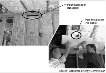
Many residential insulation installations have flaws that degrade thermal performance. Four problems are generally responsible for this degradation:
1. There is an inadequate air barrier in the building envelope, or holes and gaps within the air barrier system inhibit its ability to limit air leakage.
2. Insulation is not in contact with the air barrier creating air spaces that short-circuits the insulation’s thermal control when the air barrier is not limiting air leakage properly.
3. The insulation has voids or gaps resulting in portions of the construction assembly that are not insulated and, therefore, has less thermal resistance than other portions of the assembly.
4. The insulation is compressed, creating a gap near the air barrier and/or reducing the thickness of the insulation.
An energy credit for correctly installing an air barrier and insulation to eliminate or reduce common problems associated with poor installation are provided in the Reference Appendices, Residential Appendix RA3.5. This compliance credit applies to framed and nonframed assemblies. Residential construction may incorporate multiple frame types; for example, using a combination of nonframed walls with a framed roof/ceiling. Likewise, multiple insulation materials are often used. Framed assemblies include wood and steel construction insulated with batts of mineral fiber, mineral and natural wool, and cellulose; loose fill insulation of mineral fiber, mineral and natural wool, and cellulose, and light and medium density spray polyurethane foam; and for rigid board insulation used on the exterior or interior of framed and nonframed assemblies. Non-framed assemblies include structural insulated panels, insulated concrete forms, and mass walls of masonry, concrete and concrete sandwich panels, log walls, and straw bale.
This compliance credit can only be taken for the whole building—roof/ceilings, walls and floors, and requires field verification by a third-party HERS rater. Further explanation is provided below:
1. Compliance credit is not allowed for walls alone; or for roofs/ceilings but not walls also.
2. Compliance credit is allowed for a building built on a slab floor, where the slab has no requirement for insulation. However, if insulation is installed (i.e., slab edge insulation for radiant floor heating) then the integrity of the slab edge insulation must also be field verified in 'addition to the air barrier and insulation system for walls and the roof/ceiling.
3. Combinations of insulation types (hybrid systems) are allowed.
4. An air barrier shall be installed for the entire envelope.
5. Compliance credit is allowed for additions to existing buildings where energy compliance has been demonstrated for the “addition alone” (§150.2(a)
6. Compliance credit is not allowed for additions to existing buildings where the “existing plus alteration plus addition” approach is used (§150.2(a)2B).
Approved computer compliance modeling software automatically reduces the effectiveness of insulation for compliance purposes. This reduction is accounted for in developing the Standards and prescribing the required prescriptive measures for each climate zone to establish the standard design energy budget in performance compliance calculations. The effect of a poorly installed air barrier system and envelope insulation results in higher wall heat loss and heat gain than standard R-value and U-factor calculations would indicate. Similar increases in heat loss and heat gain are experienced for roof/ceilings where construction and installation flaws are present.

Reference Residential Appendix RA3.5.5.2.8
When metal bracing, tie-downs or steel structural framing is used to connect to wood framing for structural or seismic purposes the QII energy credit still can be taken if:
1. Metal bracing, tie-downs or steel structural framing is identified on the structural plans, and
2. Insulation is installed in a manner that restricts the thermal bridging through the structural framing assembly, and
3. Insulation fills the entire cavity and/or adheres to all sides and ends of structural assembly that separates conditioned from unconditioned space.
To take advantage of the QII energy credit two primary installation criteria must be adhered to and they both will be field verified by a HERS rater:
Reference Residential Appendix RA3.5.2
An air barrier shall be installed enclosing the entire building and when this credit is shown to be taken on compliance documentation a third-party HERS rater is required to verify the integrity of the air barrier system. The air barrier must be installed in a continuous manner across all components of framed and non-framed envelope assemblies. The installer shall provide evidence with compliance documentation that the air barrier system meets one or more of the air barrier specifications shown in Table 3-8 below. More detailed explanation is provided in Reference Appendices, Residential Appendix RA3.5. Documentation for the air barrier includes product data sheets and manufacturer specifications and installation guidelines. The third-party HERS rater shall verify that the air barrier has been installed properly and is integral with the insulation being used throughout the building.
|
Continuous Air Barrier |
A combination of interconnected materials and assemblies joined and sealed together to provide a continuous barrier to air leakage through the building envelope separating conditioned from unconditioned space, or adjoining conditioned spaces of different occupancies or uses. An air barrier is required in all thermal envelope assemblies to limit air movement between unconditioned/outside spaces and conditioned/inside spaces and must meet one of the following: 1. Using individual materials that have an air permeance not exceeding 0.004cfm/ft2 under a pressure differential of 0.3in. w.g. (1.57psf) (0.02 L/s.m2 at 75 pa) when tested in accordance with ASTM E2178; or 2. Using assemblies of materials and components that have an average air leakage not to exceed 0.04 cfm/ft2 under a pressure differential of 0.3 in. w.g (1.57psf) (0.2 L/s.m2 at 75 pa) when tested in accordance with ASTM E2357, ASTM E1677, ASTM E1680 or ASTM E283; or 3. Testing the completed building and demonstrating that the air leakage rate of the building envelope does not exceed 0.40 cfm/ft2 at a pressure differential of 0.3 in w.g. (1.57 psf) (2.0 L/s.m2 at 75 pa) in accordance with ASTM E779 or an equivalent approved method. Individual materials and assemblies of materials that can demonstrate compliance with the air barrier testing requirements must be installed according to the manufacturer's instructions and a HERS rater shall verify the integrity of the installation. Below are example materials meeting the air permeance testing performance levels of 1 above. Manufacturers of these and other product types must provide a specification or product data sheet showing compliance to the ASTM testing requirements to be considered as an air barrier. •Plywood – minimum 3/8 inch •Oriented strand board – minimum. 3/8 inches •Extruded polystyrene insulation board – minimum. ½ inch •Foil-back polyisocyanurate insulation board – minimum. ½ inch •Foil backed urethane foam insulation (1 inch) -- Closed cell spray polyurethane foam with a minimum density of 2.0 pcf and a minimum thickness of 2.0 inches -- Open cell spray polyurethane foam with a minimum density of 0.4 to1.5 pcf and a minimum thickness of 5½ inches •Exterior or interior gypsum board - minimum 1/2 inch •Cement board - minimum 1/2 inch •Built up roofing membrane •Modified bituminous roof membrane •Particleboard-minimum1/2 inch •Fully adhered single-ply roof membrane •Portland cement/sand parge ,or gypsum plaster minimum 5/8 inch •Cast-in-place and precast concrete. •Fully grouted uninsulated and insulated concrete block masonry •Sheet steel or aluminum |

All insulation shall be installed properly throughout the entire building and when this credit is taken on compliance documentation a third-party HERS rater is required to verify the integrity of the installed insulation. The installer shall provide evidence with compliance documentation that all insulation specified on compliance documentation is installed to meet specified R-values and assembly U-factors.
General insulation types are shown in Table 3-9 below. More detailed explanation is provided in the wall insulation discussion of Section 3.3.2 and in Reference Appendices, Residential Appendix RA3.5.
Documentation of insulation R-values and assembly U-factors includes product data sheets, manufacturer specifications and installation guidelines, insulation product and assembly testing information, and U-factor calculations following the procedures specified in Reference Appendices, Joint Appendix JA4, through use of the EZ-Frame Assembly Calculator, or from results of approved performance compliance computer software. The third-party HERS rater shall verify that all insulation has been installed properly and is integral with the air barrier being used throughout the building.
|
Insulation Types--framed assemblies |
There are four basic types of insulation, or insulation "systems", installed in residential buildings and their use varies based on the design and type of construction: 1. Batt and Blanket: Batt and blanket insulation is made of mineral fiber and mineral wool -- either processed fiberglass, rock or slag wool; natural wool products—animal wool or cotton based products; or cellulose materials. These products are used to insulate below floors, above ceilings, below roofs, and within walls. 2. Loose-fill: Loose-fill insulation includes loose fibers or fiber pellets that are blown into building cavities or attics using special equipment. Loose-fill insulations typically are produced using mineral fiber, mineral or natural wool (animal or cotton based products), or cellulose. They are installed in walls, floors, attics and below roofs using a dry-pack process or a moist-spray technique, and may include a netting material. 3. Rigid Board: Rigid board insulation sheathing is made from fiberglass, expanded polystyrene (EPS), extruded polystyrene (XPS), polyisocyanurate, or polyurethane. This type of insulation is used for above roof decks, exterior walls, cathedral ceilings, basement walls, as perimeter insulation at concrete slab edges, and to insulate special framing situations such as window and door headers, and around metal seismic bracing. Rigid board insulation may also be integral to exterior siding materials. 4. Spray Polyurethane Foam (SPF): A two-part liquid foamed plastic (such as polyurethane or modified urethane) material formed by the reaction of an isocyanurate and a polyol that uses a blowing agent to develop a cellular structure when spray applied onto a substrate. SPF insulation is a two-component reactive system mixed at a spray gun or a single-component system that cures by exposure to humidity. The liquid is sprayed through a nozzle into wall, roof/ceiling, and floor cavities. SPF insulation can be formulated to have specific physical properties (i.e., density, compressive strength, fire resistance and R-value). There are two types of SPF insulation: a. Low Density Open-Cell SPF (ocSPF) Insulation: A spray applied polyurethane foam insulation having an open cellular structure resulting in an installed nominal density of 0.4 to 1.5 pounds per cubic foot (pcf). b. Medium Density Closed-Cell SPF (ccSPF) Insulation: A spray applied polyurethane foam insulation having a closed cellular structure resulting in an installed nominal density of greater than 1.5 to less than 2.5 pounds per cubic foot (pcf). |
|
Insulation Types--non-framed assemblies |
There are five basic types of non-framed wall systems that provide structural as well as thermal resistance and their use varies based on the design and type of construction: 1. Structural Insulated Panel (SIP): A composite building material consisting of an insulating layer of rigid polymer foam sandwiched between two layers of structural board. The board can be sheet metal, plywood, cement or oriented strand board (OSB) and the foam is either expanded polystyrene foam (EPS), extruded polystyrene foam (XPS) or polyurethane foam. SIPs combine several components of conventional building, such as studs and joists, insulation, vapor barrier and air barrier. They can be used for many different applications, such as exterior walls, roofs, floors, and foundation systems. 2. Insulated Concrete Form (ICF): A system of formwork for concrete that stays in place as permanent building insulation and is used for cast-in-place, reinforced above and below-grade concrete walls, floors, and roofs. ICFs are interlocking modular units that can be dry-stacked (without mortar) and filled with concrete as a single concrete masonry unit (CMU). ICFs lock together externally and have internal metal or plastic ties to hold the outer layer(s) of insulation to create a concrete form for the structural walls, roof/ceilings, or floors of a building. ICFs are manufactured from several materials including: expanded and extruded polystyrene foam, polyurethane foam, cement-bonded wood fiber, and cement-bonded polystyrene beads. 2. Mass Walls: a. Masonry types include clay and concrete units, which may be solid or hollow, and glazed or unglazed. Other masonry unit types include cast stone and calcium silicate units. Concrete masonry units (CMU) are made from a mixture of portland cement and aggregates under controlled conditions. Concrete masonry units can be manufactured in different sizes and with a variety of face textures. b. Concrete and concrete sandwich panels typically use a pre-cast form by casting concrete in a reusable mold or "form" which is then cured in a controlled environment, transported to the construction site and lifted into place. Precast stone is distinguished from precast concrete by using a fine aggregate in the mixture giving the appearance of naturally occurring rock or stone. 4. Log Walls: Log walls are typically made from trees that have been cut into logs that have not been milled into conventional lumber. Logs used for walls, roofs and/or floor systems may be milled and or laminated by the manufacturer or supplier to meet specific dimensions and fitting and finishing conditions. 5. Straw Bale: Straw bale construction is a building method that uses bales of straw (commonly wheat, rice, rye and oat straw) as structural and insulating elements of the building. |
Reference Appendices, Residential Appendix RA3.8
An energy credit is allowed through the performance approach when the building’s rate of envelope air leakage is less than the air leakage rate assumed for the standard design building. A third-party HERS rater shall verify the air leakage rate shown on compliance documentation through diagnostic testing of the building’s air leakage.
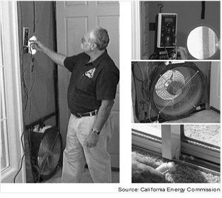
The air leakage testing process (i.e., blower door) involves closing all the windows and doors, pressurizing the house with a special fan, usually positioned in a doorway (see Figure 3-28), and measuring the leakage rate, measured in cubic feet per minute at a 50 Pa pressure difference (CFM50). This measurement procedure is described in the Reference Appendices, Residential Appendix RA3.8. It is derived from the Residential Energy Services Network's (RESNET) Mortgage Industry National Home Energy Rating Standards, Standard 800, which is based on ASTM E779 air tightness measurement protocols. This procedure requires the use of software consistent with ASTM E779. This test method is intended to produce a measure of the air tightness of a building envelope for determining the energy credit allowance for reduced building air leakage. Further explanations are described below:
A. This procedure shall only be used to verify the building air leakage rate before the building construction permit is finalized when an energy credit for reduced air leakage is being claimed on compliance documentation.
B. The Home Energy Rating System (HERS) rater shall measure the building air leakage rate to ensure measured air leakage is less than or equal to the building air leakage rate stated on the Certificate of Compliance, and all other required compliance documentation. HERS verified building air leakage shall be documented on compliance forms.
C. This is a whole building credit; therefore, no credit is allowed for the installation of individual envelope measures that may help in reducing the building’s air leakage rate, such as for an exterior air retarding wrap, or for an air barrier material or assembly meeting the requirements describe in Table 3-9 above.
1. Roof Assembly
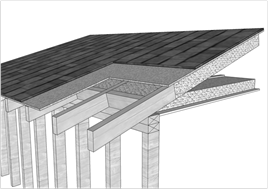
The construction techniques described below are assemblies that can be used in residential construction to help exceed minimum prescriptive requirements, particularly when using the performance compliance approach. This section describes typical constructions for roof deck insulation and raised heel trusses (also called “energy trusses”).
a. Roof Deck Insulation
An assembly and insulation alternative that helps augment conventional attic insulation that can achieve an energy compliance credit is to install insulation either directly above or directly below the roof deck. Roof deck insulation is not a prescriptive requirement but can be an inexpensive choice that improves the thermal integrity of the roof system. In 'addition, using roof deck insulation, either with conventional attic insulation that is laid horizontally over the bottom cord of the roof truss, or roof deck insulation (above or below the roof deck) without conventional horizontal attic insulation, can provide an energy tradeoff with other prescriptive measures or used to help meet high performance building energy codes in local jurisdictions, Tier 1 and Tier 2 of the CalGreen Code, or other energy efficiency targets, such as LEED© for Homes and Energy Star.
Roof deck insulation can be particularly effective when air conditioning ducts are located in the attic, since roof deck insulation considerably lowers the attic temperature during the cooling season.
b. Below Roof Deck Insulation
Insulation installed directly below the roof deck (i.e., batt, spray foam, rigid board) can be placed between the truss members and pinned in place. Other options that can provide somewhat higher R-values are to install loose fill glass fiber or cellulose between roof trusses which has netting underneath. For all cases, the attic can usually be conventionally vented using soffit, eave, and ridge vents, or other acceptable means. When insulation is installed below the roof deck the effect of radiant barrier is to be neglected. The radiant barrier is to be installed with the shiny side facing down toward the attic space. The radiant barrier is a reflective material that reduces radiant heat transfer caused by solar heat gain in the roof. For the radiant barrier to work properly it must not have insulation abutting to the shiny side.

NOTE: In some climates, placing insulation directly below the roof deck can create a condensation plane on the underside of the roof deck during the winter months. Whenever the outside air temperature is well below the dewpoint temperature of the indoor air (about 40°F to 45°F) there is potential for moisture to condense. For climate zones 11, 12, 13, 15 and 16, above deck insulation may be a better choice, particularly with a vented attic. R-8 of continuous insulation above the roof deck is approximately thermally equivalent to a R-13 batt insulation below the roof deck.
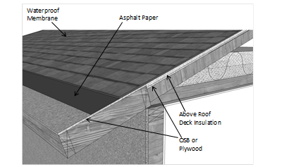
c. Above Roof Deck Insulation
Above deck insulation can also add effective R-value to the thermal integrity of the roof system. Using rigid board insulation with a minimum of R-4 helps provide additional R-value when conventional ceiling insulation is also installed and an energy credit can be taken even with a vented attic.
Compliance software can model the thermal effects and energy benefits of both above deck and below deck insulation, and the effects of a vented versus unvented attic.
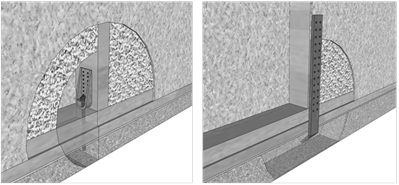
2. Attic Ventilation
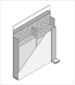
Where ceiling insulation is installed next to eave or soffit vents, a rigid baffle should be installed at the top plate to direct ventilation air up and over the ceiling insulation (See Figure 3-31). The baffle should extend beyond the height of the ceiling insulation and should have sufficient clearance between the baffle and roof deck at the top. There are a number of acceptable methods for maintaining ventilation air, including pre-formed baffles made of either cardboard or plastic. In some cases, plywood baffles are used.
The California Building Code (CBC) requires a minimum vent area to be provided in roofs with attics, including enclosed rafter roofs creating cathedral or vaulted ceilings. Check with the local building jurisdiction to determine which of the two CBC ventilation requirements are to be followed:
1. CBC, Title 24, Part 2, Vol. 1, Section 1203.2 requires that the net free ventilating area shall not be less than 1/300 of the area of the space ventilated.
2. CBC, Title 24, Part 2, Vol. 2.5, Section R806.2 requires that the net free ventilating area shall not be less than 1/150 of the area of the space ventilated. This ratio may be reduced to 1/300 if a ceiling vapor retarder is installed.
In either situation, a minimum of 50% of the vents must be located in the upper portion of the space being ventilated at least 3 feet above eave or cornice vents.
Ventilated openings are covered with corrosion resistant wire cloth screening or similar mesh material. When part of the vent area is blocked by meshes or louvers, the resulting “net free area” of the vent must be considered when meeting ventilation requirements.
Many jurisdictions in California are covered by Wildland Urban Interface (WUI) regulations where specific measures for construction materials must be used to improve fire resistance for the building. These regulations require special vents that are expressly tested to resist the intrusion of flame and burning embers. Check with the building department to ensure compliance with local codes.
a. Wood Rafter Constructions
Ventilating framed rafter spaces is more difficult than ventilating attics because each framing cavity requires its own vent openings. It is common practice with loose-fill insulation material to completely fill the cavity so that there is no ventilation at all. With batt insulation it is possible to ventilate above the insulation using higher density (cathedral ceiling) batts because this material is specifically manufactured to allow a minimum of 1 inch above the top of the insulation to allow for ventilation. If spray polyurethane foam is used, it is applied to the underside of the roof deck leaving no ventilation space.
Attic ventilation, particularly in hotter climate zones, can provide an energy benefit. However, no energy credit is allowed for reducing the ventilation area below building code requirements.


3. Unvented Attic Assemblies
Attic ventilation is the traditional way of controlling temperature and moisture in an attic. In an unvented attic (conditioned attic) assembly insulation is applied directly at the roofline of the building, either above or below the structural roof sheathing. The roof system becomes part of the insulated building enclosure. For this case, the thermal boundary of the building results in an unconditioned attic space between the ceiling gypboard and the insulated roof above.
The provisions of CBC, Title 24, Part 2, Vol. 2.5, Section R806.4 describes conditions for insulation placed at the roof of the building as opposed to on top of the horizontal ceiling. Unvented attic assemblies are allowed provided that:
A. Air-impermeable insulation is used below and in direct contact with the underside of the roof sheathing, or
B. Air-permeable insulation is used below and in direct contact with the underside of the roof sheathing and rigid board or sheet insulation of at least R-4 is used above the roof sheathing, or
C. Air-impermeable insulation is used below and in direct contact with the underside of the roof sheathing and an additional layer of air-permeable insulation is installed directly under the air-impermeable insulation.
Check with the local building jurisdiction to determine their specific requirements for unvented attic conditions.
A building that employs an unvented attic with above or below roof deck insulation can attain significant energy credits due to the increased thermal benefits of the insulation R-value, plus the reduction of duct conduction and leakage losses (bringing ducts within the conditioned space). Combining this with the additional design improvement of low air leakage for the rest of the building would achieve significant energy savings and compliance energy credit.
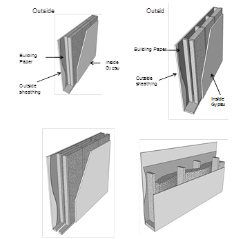
4. Wall Assembly
See Energy Commission videos
Section 3.9.6 Item 4 Sub-topics
More insulation is almost always better than less. Insulation is one of the least expensive measures to improve building energy efficiency. Insulation requires no maintenance, helps improve indoor comfort, and provides excellent sound control. Builders and designers who tout meeting minimum insulation requirements for new buildings are not providing consumers and homeowners with a home of great value. Buildings that comply minimally with the standards represent the worst buildings allowed by code. Adding extra insulation at a later time is much more expensive than simply maximizing insulation levels at the beginning of construction.
Thermal batts of glass fiber, mineral and natural wool, and cotton material are some of the most widely used insulation in the marketplace. They offer ease of installation with R-values set by the manufacturer based on size and thickness. They are available with facings, some as vapor retarders, and have flanges to aid in installation to framed assemblies. They also are available as unfaced material and can be easily friction-fitted into framed cavities. Batt and blanket thermal insulation material have more testing for sound attenuation than any other insulation type. However, in some instances manufacturers of blown or sprayed insulation material may have testing information supporting their product’s sound performance for special applications with higher values typically found for thermal batts.
Batt and blanket insulation allow easy inspection and installation errors can readily be identified and remedied, including breeches in the air barrier system that allow air leakage. Nevertheless, care should always be taken to install the insulation properly, filling the entire cavity, and butting ends or sides of the batt material to ensure uniformity of the installation. Batt and blanket insulation material must be split to allow for wiring, plumbing, and other penetrations within the framed cavity area.
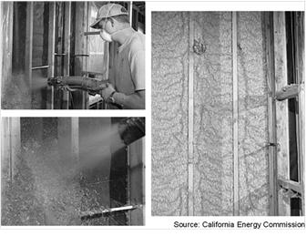
Blown or sprayed wall insulation can be an effective way to deal with the irregularities of wall and ceiling cavities, especially the spaces around pipes, electric cables, junction boxes, and other equipment that is embedded in cavities. There are several commonly used types of insulation that have a blown or sprayed process for its installation, including: cellulose, fiberglass, and spray polyurethane foam (SPF). The R-value of blown or sprayed wall insulation material is determined by the applicator at the site. This differs from manufactured products such as fiberglass or mineral wool batts whose R-value has been tested and arrives at the construction site in preformed lengths with set R-value thicknesses.
Blown or sprayed wall insulation must be thoroughly checked to insure the R-value is achieved. Line of sight down a wall section can deceivingly hide imperfections in the installation leading to underachieving stated R-values. Depressions and voids within the insulated cavity are areas lacking in their R-value performance. Where netting is used, over-spraying can result in a higher installed density (higher R-value) but can be troublesome for attaching gypboard to wall framing. Where cavities have been under-sprayed, there may be voids or “soft” areas under the netting. These areas are often re-sprayed again, or the area is removed of its insulation material and a thermal batt is installed in its place.
Cellulose is basically paper that has been treated for flame- and insect-resistance. Loose fill cellulose is commonly used in attic applications. For walls, the cellulose material is typically mixed with a water- and starch-based binder. The binder causes the insulation to adhere to itself and stick to the surfaces of the wall cavity. Excess insulation that extends past the wall cavity is scraped off with a special tool and recycled into the insulation hopper with fresh material for further installations. R-value is dependent on the installed density of the material at the building site and the building official should ensure the installed density meets manufacturer specifications. Cellulose insulation that dislodges from the cavity is often re-sprayed again, or the area is removed of cellulose and a thermal batt is installed in its place.
Loose fill fiberglass insulation is made up of small glass fibers. The product is similar to lose fill fiberglass that is commonly used in attics, but for walls it can be installed behind a netting fabric or mixed with a water based adhesive. The adhesive causes the insulation to adhere to itself and stick to surfaces of the wall cavity. Excess insulation that extends past the wall cavity is scraped off and recycled. R-value is dependent on the installed density of the material at the building site and the building official should ensure the installed density meets manufacturer specifications.
Spray polyurethane foam insulation is a foamed plastic formed by the combination of chemicals and a blowing agent applied using a spray gun. SPF insulation is spray applied to fully adhere to the joist and other framing faces to form a complete air seal within the construction cavities. R-value is dependent on the installed thickness and the building official should ensure the thickness and uniformity of the SPF material within each cavity space of framed assemblies meets manufacturer specifications. When installed on the underside of the roof deck and exposed to the attic space below SPF must be separated from the interior of the building by an approved thermal barrier consisting of 1/2-inch (12.7 mm) gypsum wallboard or equivalent thermal barrier material (Section 316.4, CBC).
There are two types of SPF insulation: medium-density closed cell (ccSPF), and light-density open cell (ocSPF) insulation. They have different insulating properties and compliance requirements as described below:
A. ccSPF has been assigned a default R-value of 5.8 per inch for compliance purposes and a nominal density of greater than 1.5 to less than 2.5 pounds per cubic foot (pcf). The average thickness of the foam insulation must meet or exceed the required R-value. Depressions in the foam insulation’s surface shall not be greater than 1/2-inch of the required thickness at any given point of the surface area being insulated. ccSPF is not required to fill the cavity.
B. ocSPF has been assigned a default R-value of 3.6 per inch for compliance purposes and a nominal density of 0.4 to 1.5 pounds per cubic foot (pcf). ocSPF insulation is sprayed then expands to fill the framed cavity. Excess insulation is removed with a special tool. The average thickness of the foam insulation must meet or exceed the required R-value. Depressions in the foam insulation surface shall not be greater than 1 inch of the required thickness provided these depressions do not exceed 10% of the surface area being insulated. ocSPF must fill the cavity of 2x4 framing.
|
Thickness of SPF Insulation |
R11 |
R13 |
R15 |
R19 |
R21 |
R22 |
R25 |
R30 |
R38 |
|
Required thickness of ccSPF Insulation (inches) |
2.00 |
2.25 |
2.75 |
3.50 |
3.75 |
4.00 |
4.50 |
5.25 |
6.75 |
|
Required thickness of ocSPF Insulation (inches) |
3.0 |
3.5 |
4.2 |
5.3 |
5.8 |
6.1 |
6.9 |
8.3 |
10.6 |
Alternatively, the total R-value may be calculated based on the thickness of insulation multiplied by the "tested R-value per inch" as 'listed in the Table of R-values or R-value Chart from the manufacturer's current ICC Evaluation Service Report (ESR) that shows compliance with Acceptance Criteria for Spray-Applied Foam Plastic Insulation-AC377. Overall assembly U-factors are determined by selecting the assembly type, framing configuration, and cavity insulation from the appropriate Reference Joint Appendix JA4 table or other approved method specified in Section JA4 of the Reference Appendices.
1. ccSPF installed as an air barrier shall be a minimum of 2.0 inches in thickness; alternatively, ccSPF insulation shall be installed at a thickness that meets an air permeance no greater than 0.02 L/s-m2 at 75 Pa pressure differential when tested in accordance to ASTM E2178 or ASTM E283.
2. ocSPF installed as an air barrier shall be a minimum of 5.5 inches in thickness; alternatively, ocSPF insulation shall be installed at a thickness that meets an air permeance no greater than 0.02 L/s-m2 at 75 Pa pressure differential when tested in accordance to ASTM E2178 or ASTM E283.
A change from wood framing to metal framing can significantly affect compliance. Metal framed assemblies are often chosen where greater structural integrity is necessary, or in climate conditions where greater durability is desired from the affects of excessive moisture exposure. Metal framed wall construction generally requires a continuous layer of rigid insulation to meet the mandatory minimum wall insulation levels and/or the prescriptive requirements since metal is more conductive than wood. In Reference Joint Appendix JA4, Tables 4.2.4 and 4.2.5 have U-factors for metal-framed ceiling/roof constructions. Table 4.3.4 has U-factors for metal-framed walls. Tables 4.4.4 and 4.4.5 have U-factors for metal-framed floors.
To comply prescriptively, a non-wood framed assembly, such as a metal framed assembly, must have an assembly U-factor that is equal or less than the U-factor of the wood framed assembly for that climate zone. Compliance credit is available through the performance approach for metal framed assemblies that exceed the prescriptive requirements of the equivalent wood framed assemblies.
Log homes are an alternative construction type used in some parts of the state. Log home companies promote the aesthetic qualities of solid wood construction and can "package" the logs and deliver them directly to a building site. Some companies provide log wall, roof, and floor systems with special insulating "channels" or other techniques to minimize the effect of air infiltration between log members and to increase the thermal benefit of the logs.
Log walls do not have framing members like conventional wood stud walls. Therefore, the mandatory requirement for a minimum of R-13 wall insulation does not apply.
Otherwise, in prescriptive compliance log walls must meet the same thermal requirements as other construction types. For performance compliance, consult the compliance software vendor’s documentation for any unique modeling requirements for mass walls using values from Reference Appendices. In prescriptive compliance, the walls will qualify as either light mass or heavy mass walls depending on the thickness – remember a heat capacity (HC) of 8.0 Btu/°F-ft² is equivalent to a heavy mass wall (40 lb/ft³). The prescriptive requirements for heavy mass walls are less stringent than the criteria for wood-framed walls. Reduced insulation is allowed because the effects of the thermal mass (interior and exterior) can compensate for less insulation.
The thermal performance of log walls is shown in Reference Joint Appendix JA4, Table 4.3.11. The U-factor ranges from 0.133 for a 6-inch wall to 0.053 for a 16-inch wall. The U-factor of an 8-inch wall is 0.102, which complies with the R-13 prescriptive requirements. U-factors for other log wall constructions (not shown in Reference Joint Appendix JA4) would have to be approved by the Energy Commission through the exceptional methods process.
Log walls have a heat capacity that is in excess of conventional construction. Reference Joint Appendix JA4 [Table 4.3.11 Thermal Properties of Log Home Walls] shows that a 6-inch wall has an HC of 4.04 which increases to 10.77 for a 16-inch wall. The thermal mass effects of log home construction can be accounted for within the performance approach.
Air infiltration between log walls can be considerably different among manufacturers depending upon the construction technique used. For purposes of compliance, infiltration is always assumed to be equivalent to a wood-frame building. However, the builder should consider using a blower door test to find and seal leaks through the exterior walls.
Straw bale construction is regulated within the CBC and specific guidelines are established for moisture content, bale density, seismic bracing, weather protection, and other structural requirements.
The Energy Commission has determined specific thermal properties for straw bale walls and thermal mass benefits associated with this type of construction. The performance compliance approach can be used to model the heat capacity characteristics of straw bales.
Straw bales that are 23 inch by 16 inch are assumed to have a thermal resistance of R-30, whether stacked so the walls are 23 inch wide or 16 inch wide. The minimum density of load bearing walls is 7.0 lb/ft3, and this value or the actual density may be used for modeling straw bale walls in the performance approach. Specific heat is set to 0.32 Btu/lb-°F. Volumetric heat capacity (used in some computer programs) is calculated as density times specific heat. At a density of 7 lb/ft³, for example, the volumetric heat capacity is 2.24 Btu/ft³-°F.
The minimum dimension of the straw bales when placed in the walls must be 22 inch by 16 inch and there are no restrictions on how the bales are stacked. Due to the higher resistance to heat flow across the grain of the straw, a bale laid on edge with a nominal 16-inch horizontal thickness has the same R-Value (R-30) as a bale laid flat.
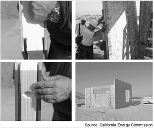
Structural Insulated Panels (SIPS) are a non-framed advanced construction system that consists of rigid insulation (usually expanded polystyrene) sandwiched between two sheets of OSB or plywood. Little or no structural framing penetrates the insulation layer. Panels are typically manufactured at a factory and shipped to the job site in assemblies that can be as large as 8 ft by 24 ft.
In the field, the SIPS panels are joined in one of three ways: (1) single or double 2x splines, (2) I-joists, or (3) with OSB splines. The choice of these options affects thermal performance and structural capacity. The 2x and I-joist spline types each fit in a recess of the foam core, between the two layers of plywood or OSB. Reference Joint Appendix JA4, Table 4.2.3 contains U-factors for roof/ceiling assemblies, Table 4.3.2 has U-factors for SIPS wall assemblies and Table 4.4.3 has U-factors for SIPS floor constructions. U-factors used for compliance must be taken from these tables, through the EZ-Frame assembly calculator, or by using approved performance compliance software.
Insulating Concrete Forms (ICFs) are a concrete forming system that uses stay-in-place panels made from a variety of insulating materials for constructing cast-in-place solid concrete walls. Three factors contribute to the energy efficiency of buildings using an ICF wall: (1) continuous rigid insulation on both sides of a high-mass core, (2) elimination of thermal bridging from wood framing components, and (3) a high degree of air-tightness inherent to this method of construction.
Climate zones with large daily temperature fluctuations have the greatest potential to benefit from the time lag and temperature dampening effects of these high-mass envelope systems. However, this combination of mass and insulation is beneficial in almost all climates with the possible exception of mild coastal climate zones.
There are three basic types of ICFs: flat wall, waffle-grid and screen-grid. A flat wall ICF results in a wall with a consistent and continuous thickness of concrete. A waffle-grid ICF creates a concrete waffle pattern, an uninterrupted-grid, with some concrete sections thicker than others. A screen-grid ICF consists of a discrete post-and-beam structure with the concrete completely encapsulated by the foam insulation, except at the intersection of posts and beams. The insulating panels for all three ICF types are most commonly made from expanded polystyrene (EPS) and extruded polystyrene (XPS) rigid insulation boards. Insulating panels are also made from polyurethane, composites of cement and EPS, and composites of cement and shredded wood fiber, although these tend to be proprietary materials developed by the ICF manufacturer.
Plastic or metal cross-ties, consisting of two flanges and a web, separate the insulating panels and provide structural integrity during the concrete pour resulting in a uniform wall thickness. A variety of wall thicknesses can be obtained by changing the length of the web. The area of attachment of the cross-ties to the insulating form provides a secure connection surface located at standard spacings for mechanical attachment of finish materials to the interior and exterior of the wall. ICFs can be used to construct load-bearing and non-load bearing walls, above- and below-grade walls, and can be designed to structurally perform in any seismic zone.
The ICF system is modular and stackable with interlocking edges. The materials can be delivered as pre-assembled blocks or as planks that require the flanges and web to be assembled during construction. The forms vary in height from 12” - 24” and are either 4’ or 8’ long. Vertical panels come in similar modules, but are stacked vertically. ICF panels are typically available with core thickness ranging from 4” to 12”.
The thermal aspects of ICFs are represented in the Reference Joint Appendix JA4, Table 4.3.13.
Advanced Wall Systems (AWS), also known as Optimum Value Engineering (OVE), refers to a set of framing techniques and practices that minimize the amount of wood and labor necessary to build a structurally sound, safe and durable, energy efficient building. AWS improves energy and resource efficiency while reducing first costs.
Reducing the amount of wood in wood framed exterior walls improves energy efficiency, allowing more insulation to be installed, and has greater resource efficiency for the materials being used. In 'addition, fewer framing studs reduces the effects of “thermal bridging” and increases the amount of insulation in the wall, resulting in a more energy efficient building envelope. The framing factor assumed for calculating the energy performance of a wood framed 2x4 wall at 16”oc is 25%. When AWS is used the framing factor is reduced to 17%, reflecting the improved energy performance of the wall system.
While AWS represents a range of practices, it must be adequately inspected to ensure framing contractors have adhered to all best practice construction throughout the exterior envelope. Examples of construction practices for AWSs that should be followed and that can be used as a general guide for enforcement are provided below:
1. Use at a minimum 2x6 at 24” on-center wall framing
2. Use precise engineering of headers on load-bearing walls
3. Install 2x4, 2x6, or I-joist headers on exterior non-load-bearing walls
4. Eliminate cripple studs at window and door openings less than 4 feet in width
5. Align window/door openings with standard stud spacing
6. The king stud, on at least one side of the window/door opening, must take the place of an on-layout AWS stud
7. Use two-stud corners instead of 3-stud corners
8. Nailing for interior gypsum board can be accomplished with drywall clips, 1x nailer strip, recycled plastic nailing strip. Drywall clips reduce the potential for drywall cracking
9. Ladder block where interior partitions intersect exterior walls, instead of 3-stud channels
10. Eliminate unnecessary double floor joists underneath non-bearing walls
11. Use metal let-in T-bracing or other methods on non-shear walls to allow full insulation
12. Include detailed framing plans and elevations on the construction permit plan set
13. Optimize house design for efficient material use (e.g. reducing header spans, designing exterior surfaces in two foot modules, designing clear spans to eliminate interior bearing walls)
14. Build with “insulated headers” (a “sandwich” of two solid or engineered lumber components with a layer of foam insulation in the middle or on one or both sides of the header)
15. Use engineered lumber. Examples include: “I”-joists, open web floor trusses; 2x “raised heel” roof trusses, glulam beams, laminated veneer lumber (LVL), laminated strand lumber (LSL), parallel strand lumber (PSL), oriented strand board (OSB)
16. Eliminate trimmers at window and door opening headers less than 4 feet in width, only when rated hangers are utilized and noted on the plans.
17. Use 2x4 or 2x3 interior non-load-bearing walls
18. Integrate framing design with HVAC system
19. Use “inset” shear wall panels
The graphic below is a description of a typical AWS and the assembly characteristics that are used in the prescriptive and performance compliance approaches to support it use. But note, the building official must ensure during the framing inspection that all elements of AWS have been met.
|
Layer |
Assembly Type: Wall 2x6 @ 24” oc AWS |
R-Value | |
|
Framing Material: Wood |
Framing Factor |
17 | |
|
Assembly Components |
Cavity (Rc) |
Frame (Rf) | |
|
1 |
Outside air film |
0.17 |
0.17 |
|
2 |
7/8 inch 3-coat stucco |
0.18 |
0.18 |
|
3 |
3/8 inch sheathing |
0.47 |
0.47 |
|
4 |
R-21 insulation |
21.0 |
-- |
|
5 |
2x6 douglass fir framing @ R-1.086/inch |
-- |
5.973 |
|
6 |
½ inch gypboard |
0.45 |
0.45 |
|
7 |
Inside air film |
0.68 |
0.68 |
|
|
Subtotal |
23.01 |
7.983 |
|
|
[1/Rc x (1-Frame% / 100)] + [(1/Rf)] x (Frame% / 100)] = Assembly U-factor |
Assembly |
0.057 |
Assumptions: Values in Table 3-11 were calculated using the parallel heat flow calculation method, documented in the 2009 ASHRAE Handbook of Fundamentals. The construction assembly assumes an exterior air film of R-0.17, a 7/8 inch layer of stucco of R-0.18 (SC01), building paper of R-0.06 (BP01), sheathing or continuous insulation layer if present, the cavity insulation / framing layer, ½ inch gypsum board of R-0.45 (GP01), and an interior air film 0.68. The framing factor is assumed to be 25 percent for 16 inch stud spacing, 22 percent for 24 inch spacing, and 17 percent for Advanced Wall System (AWS).
Actual cavity depth is 3.5 inch for 2x4, 5.5 inch for 2x6. The thickness of the stucco is assumed to be reduced to 3/8 inch (R-0.08) when continuous insulation is applied.
Double wall and staggered wall systems were developed to better accommodate electrical and plumbing systems, allow higher levels of insulation, and provide greater sound attenuation. The advantages of these types of wall systems are that:
1. Smaller dimensional lumber can be used
2. Easier to install installation properly
3. Eliminates thermal bridging through the framing
4. Reduces sound transmission through the wall
With double walls, insulation may be on one side of the wall or on both (higher R-values). It is not uncommon to find double walls with insulation installed within the outside wall cavities, leaving the inside wall sections open for wiring and plumbing purposes.
With staggered walls, thermal batt insulation may be installed horizontally or vertically, butting the sides of the insulation until the cavity across the entire wall section is completely filled.
5. Floor Assembly
a. Controlled Ventilation Crawlspace (CVC)
CVC Eligibility Criteria in 2013 Reference Appendices, Residential Appendix RA4.5.1
Buildings having crawlspace foundations must meet mandatory and prescriptive requirements for insulation of a raised floor separating the unconditioned crawlspace from conditioned space above (§150.0(d) and §150.1(c)1C). An alternative to under floor insulation is insulating the stem wall of the foundation crawlspace. Insulating the crawlspace foundation can improve the thermal efficiency of the floor system by:
1. Reducing heat transfer into the unconditioned crawlspace,
2. Reducing moisture buildup in the crawlspace, and
3. Minimizing insulation exposed to adverse weather prior to enclosure of the building shell
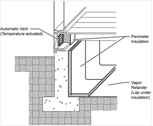
An energy credit can be taken in performance compliance software for Controlled Ventilation Crawlspace (CVC). This credit requires insulating the foundation stem wall, the use of automatically controlled crawlspace vents, and vapor retarder covering the entire ground soil area for moisture control on the crawlspace floor (see Section 3.3. V, Vapor Retarder).
All building designs should ensure that proper site engineering and drainage away from the building is maintained, this includes landscaping techniques that emphasize sound water management strategies:
A. Drainage: Crawlspace buildings in particular are susceptible to moisture ponding when good drainage and/or moisture removal designs are not employed.
B. Ground water and soils: Local ground water tables at maximum winter recharge elevation should be below the lowest excavated elevation of the site foundation. Sites that are well drained and that do not have surface water problems are generally good candidates for this stem wall insulation strategy. However, allowance for this alternative insulating technique is entirely at the building officials' discretion. The building permit applicant should be prepared to provide supporting information that site drainage strategies (e.g., perimeter drainage techniques) will prevent potential moisture concerns.
The following eligibility criteria (see Reference Appendices, Residential Appendix RA4.5.1) are required in order to use the CVC energy credit:
C. Ventilation: All crawlspace vents must have automatic vent dampers. Automatic vent dampers must be shown on the building plans and installed. Dampers shall be temperature actuated to be fully closed at approximately 40°F and fully open at approximately 70°F. Cross-ventilation consisting of the required vent area shall be distributed between opposing foundation walls.
D. Insulation: The R-value of insulation placed on the foundation stem wall shall be equal to or greater than the wall insulation above the raised floor. Stem wall insulation shall run vertically along the stem wall and horizontally across the crawlspace floor for a distance of 2 feet (24 inches).
E. Direct Earth Contact—Foam plastic insulation used for crawlspace insulation having direct earth contact shall be a closed cell water resistant material and meet the slab edge insulation requirements for water absorption and water vapor transmission rate specified in the mandatory requirements (§110.8(g)1).
A Class I or Class II vapor retarder must be placed over the earth floor of the crawl space to reduce moisture entry and protect insulation from condensation in accordance with Reference Residential Appendix RA4.5.2. This requires essentially a polyethylene type ground cover having a minimum 6 mil thickness (0.006 inch) or approved equal. The vapor retarder must be overlapped a minimum of 6 inches at joints and shall extend over the top of footings and piers. All overlapping of joints shall be sealed with tape, caulk or mastic.
Penetrations, tears and holes in the vapor barrier shall be sealed with tape, caulk or mastic.
The vapor retarder shall be Class I or Class II and rated as 1.0 perm or less.
Edges of the vapor retarder shall be turned up a minimum of 4 inches at the stem wall and securely fastened before insulation is installed.
In sloping crawlspace ground soil areas, the vapor retarder shall be securely held in place, such as spiked with 5 inch gutter nails then have proper sealing of penetration holes.
The vapor retarder shall be shown on the plans.
6. Other Assemblies
A. Thermal Mass
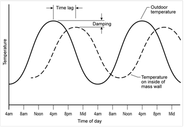
Thermal mass consists of exposed tile floors over concrete, mass walls such as stone or brick, and other heavy elements within the building envelope that serve to stabilize indoor temperatures. Thermal mass helps temper interior temperature, storing heat or cooling for use at a later time. In California’s central valley and desert climates, the summer temperature range between night and day can be 30°F or more and thermal mass can be an effective strategy to reduce daytime cooling loads.
When thermal mass exists in exterior walls, it works to stabilize temperatures in two ways. First, there is a time delay between when the outside temperature of the wall reaches its peak and when the inside of the wall reaches its peak. For an 8-inch to 12-inch concrete wall, this time delay is on the order of 6 to 10 hours. Second, there is a dampening effect whereby the temperature range on the inside of the house is less than the temperature range on the outside of the house. These effects are illustrated in the following figure.
When the performance method is used, credit is offered for increasing thermal mass in buildings. However, credit for thermal mass in the proposed design may be considered only when the proposed design qualifies as a high mass building. A high mass building is one with thermal mass equivalent to having 30 percent of the conditioned slab floor exposed and 15 percent of the conditioned non-slab floor exposed with the equivalent of 2 inch-(50 mm) thick concrete. This procedure is automated in Energy Commission approved computer.