
The water heating distribution system is the configuration of piping (and pumps and controls in the case of recirculating systems) that delivers hot water from the water heater to the end use points within the building. For systems designed for single family buildings or individual dwelling units in a building the system will resemble one of the system types described below under dwelling unit distribution systems. In multi-family buildings the use of a central water heater and central recirculation distribution system that brings hot water close to all the dwelling units is also common. A description of the recognized systems for serving single and multiple dwelling units are listed in the following two sections. Any hot water distribution system that is installed that does not meet all of the installation guidelines discussed in this 'manual and in the Residential Appendix RA3 and RA4 must either have the deficiencies corrected or compliance calculations must be redone using the performance approach assuming that the installed distribution system is sub-standard.
1. Standard Distribution System (Trunk and Branch and mini-manifold configurations)
The most basic plumbing layout, and assumed as the reference design in the performance approach is represented by the conventional trunk and branch layout. This layout of a trunk and branch system may include one or more trunks each serving a portion of the building. The trunks are subdivided or branch off into branches, which serve specific rooms, and these are in turn divided into twigs which serve a particular point of use. This distribution system class includes mini-manifold layouts (see Figure 5-2 which incorporate trunk lines feeding remote manifolds that then distribute via twigs to the end use points. A Standard Distribution System may not incorporate a pump for hot water recirculation. Piping cannot be run up to the attic and then down to points of use on the first floor.
Installation Criteria and Guidelines
No pumps may be used to recirculate hot water with the Standard system. All applicable mandatory features must be met. When designing a trunk and branch the concern is keeping all segments of the system as short and as small a diameter as possible. Even an insulated pipe will lose most of its stored heat within thirty minutes. The other issue to realize is that if a cold line is to get hot water, it will require not only running out all the water in the pipe but up to an additional third of the volume again to heat the pipe enough so that the water at the point of use will be an acceptable temperature. The adopted requirements for installation guidelines are included in RA3 and RA4.
1. Central Parallel Piping System
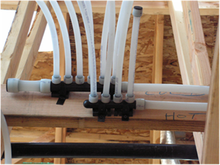
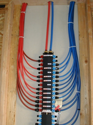
The primary design concept in a central parallel piping system is an insulated main trunk line runs from the water heater to one or more manifolds, which then feeds individual use points with ½” or smaller plastic piping. The traditional central system with a single manifold (Figure 5-3) must have a maximum pipe run length of 15 ft between the water heater and the manifold. With the advent of mini-manifolds, the central parallel piping system can now accommodate multiple mini-manifolds in lieu of the single central manifold, provided that a) the sum of the piping length from the water heater to all the mini-manifolds is less than 15 ft, b) all piping downstream of the mini-manifolds is nominally ½” or smaller.
Installation Criteria and Guidelines
All applicable mandatory measures must be met. Piping from the manifold cannot be run up to the attic and then down to points of use on the first floor. The intent of a good parallel piping design is to minimize the volume of water entrained in piping between the water heater and the end use points, with a focus on reducing the length of the 3/4 inch or 1 inch line from the water heater to the manifold(s). To encourage reducing the water heater to manifold length, there is a distribution system compliance credit for installations that are HERS-verified to have no more than 5 ft of piping between the water heater and the manifold(s). The manifold feeds individual hot water use points with 3/8 or 1/2 inch PEX) tubing. (Check with local jurisdictions on the use of 3/8 inch piping, since many do not allow it without engineering approval.) The adopted requirements for installation guidelines are included in RA3 and RA4.
2. Point of Use
A point of use distribution system design significantly reduces the volume of water between the water heater and the hot water use points. To use this type of system will requires a combination of good architectural design (water heater location adjacent to hot water use points), an indoor mechanical closet, or the use of multiple water heaters. Figure 5-4 provides an example of the latter approach where three water heaters are installed in close proximity to the use points. For compliance with this credit, HERS verification is required. This system is not applicable to systems serving multiple dwelling units.
Installation Criteria and Guidelines
All applicable mandatory features must be met, and the distance between the water heater and any fixture using hot water cannot exceed the length specified in Table 5-4 below, as measured by the HERS rater. The adopted requirements for installation guidelines are included in RA3 and RA4. All water heaters and hot water fixtures must be shown on plans submitted for local building department plan check.
Exception: Washing machines for clothing may be located more than 8 feet from the water heater.
|
Size Nominal, Inch |
Length of Pipe (feet) |
|
3/8” |
15 |
|
1/2” |
10 |
|
3/4” |
5 |
3. Compact Design
A compact distribution system design means that all the hot water use points in a non-recirculating distribution system are within a specified length of piping to the water heater that serves those fixtures. Table 5-5 below specifies the maximum pipe run length that meets the compact design criteria based on floor area served (floor area served = building conditioned floor area divided by the number of water heaters), which recognizes that multiple water heaters may be beneficial in achieving a more compact distribution system. To be eligible, for the compact credit, the length must be physically measured and field-verified by a HERS rater. The adopted requirements for installation guidelines are included in RA3 and RA4.
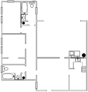
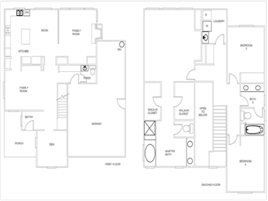
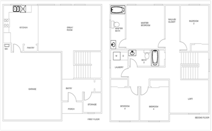
Typical hot water distribution designs are often much larger than they need to be in terms of pipe length. A big part of the problem is a house design process which doesn’t take into account the location of the water heater relative to bathrooms and kitchen use points. Figure 5-5 below shows a fairly common house layout with the water heater located in the corner of the garage, and hot water use points in each corner of the house. A much improved house design is shown in Figure 5-6, where the water heater location is in close proximity to the kitchen and bathrooms and laundry area. Early in the design stage, the location of hot water use points can play a big role in achieving the benefits associated with a compact distribution system design.
|
Floor Area |
Maximum Water Heater |
|
Served (ft2) |
To Use Point Distance (ft) |
|
< 1000 |
28’ |
|
1001 – 1600 |
43’ |
|
1601 – 2200 |
53’ |
|
2201 – 2800 |
62’ |
|
>2800 |
68 |
4. Recirculation System – Non-Demand Control Options
This distribution system type encompasses all recirculation strategies that do not incorporate a demand control strategy to minimize recirculating pump operation. Under this category, recirculation system types include uncontrolled continuous recirculation, timer control, temperature control, and time/temperature controls. The intent is to clearly distinguish between recirculation system control options that result in very little daily pump operating time (demand control strategies) and the other strategies, where pump run time is much more uncertain. Recirculation systems are known to save water (since the hot water is much closer to the use points), but the energy impact can be very high in a poorly designed and/or controlled system.
Installation Criteria
All piping used to recirculate hot water must be insulated to meet the mandatory requirements. Since the Standards require pipe insulation for recirculating systems, these systems are not eligible for the Pipe Insulation credit. For systems serving a single dwelling unit, the recirculating loop within a dwelling unit must be laid out to be within 8 ft of all hot water fixtures served by the recirculating loop. As with all recirculation systems, an intelligent loop layout (loop in-board of hot water use points) and proper insulation installation are essential in obtaining desired performance. Piping in a recirculation system cannot be run up to the attic and then down to points of use on the first floor. The adopted requirements for installation guidelines are included in RA3 and RA4
5. Recirculation System – Demand Control
A demand-control recirculation system uses brief pump operation in response to a hot water demand “signal” to circulate hot water through the recirculation loop. The system must have a temperature sensor, typically located at the most remote point of the recirculation loop. The sensor provides input to the controller to terminate pump operation when the sensed temperature rises. Typical control options include manual push button controls or occupancy sensor controls installed at key use areas (bathrooms and/or kitchen). Push button control is preferred from a performance perspective, since it eliminates “false signals” for pump operation that an occupancy sensor could generate. The adopted requirements for installation guidelines are included in RA3 and RA4
Installation Criteria
All criteria listed for continuous recirculation systems apply. Piping in a recirculation system cannot be run up to the attic and then down to points of use on the first floor.
Pump start-up must be provided by a push button, flow switch, or occupancy sensor. Pump shut-off must be provided by a combination of a temperature sensing device that shuts off the pump when hot water reaches the location of use, and by a timer which limits maximum pump run time to two minutes or less.
For a system serving a single dwelling, push buttons and sensors must be installed in all locations with a sink, shower, or tub, with the exception of the laundry room.
Plans must include a wiring/circuit diagram for the pump and timer/temperature sensing device and specify whether the control system is manual (push button or flow switch) or other control means, such as an occupancy sensor.
1. Multiple Dwelling Units: Central Demand Recirculation System (Standard Distribution System)
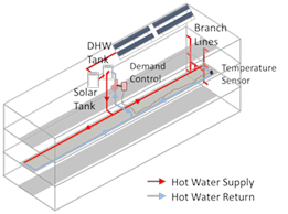
The standard distribution system for water heaters serving multiple dwelling units incorporates recirculation loops, which bring hot water to different parts of the building, and a demand control, which automatically shuts off the recirculation pump when the recirculation flow is not needed. In summary, central recirculation systems include three components, recirculation loops, branch pipes, and pipes within dwelling units. Recirculation loops are used to bring hot water close to all dwelling units, but are not expected to go through each dwelling unit. Branch pipes are used to connect pipes within dwelling units and the recirculation loops. This concept is illustrated in Figure 5-7. Designs of distribution systems within dwelling units are similar to those serving single dwelling units, described in Section 5.4.1.
Central recirculation water heating systems which use temperature, timer or no controls can use a default recirculation system type if performance compliance is used.
Demand controls for central recirculation systems are automatic control systems that control the recirculation pump operation based on measurement of hot water demand and hot water return temperatures.
2. Multiple Dwelling Units: Recirculation Temperature Modulation Control
A recirculation temperature modulation control shall reduce the hot water supply temperature when hot water demand is determined to be low by the control system. The control system may use a fixed control schedule or dynamic control schedules based measurements of hot water demand. The daily hot water supply temperature reduction, which is defined as the sum of temperature reduction by the control in each hour within a 24-hour period, shall be more than 50 degrees Fahrenheit to qualify for the energy savings credit. Qualifying equipment shall be listed with the Commission.
Recirculation systems shall also meet the requirements of §110.3.
3. Multiple Dwell Units: Recirculation Continuous Monitoring Systems
Systems that qualify as a recirculation continuous monitoring systems for domestic hot water systems serving multiple dwelling units shall record no less frequently than hourly measurements of key system operation parameters, including hot water supply temperatures, hot water return temperatures, and status of gas valve relays of water heating equipment. The continuous monitoring system shall automatically alert building operators of abnormalities identified from monitoring results. Qualifying equipment or services shall be listed with the Commission.
Recirculation systems shall also meet the requirements of §110.3.
4. Non-recirculating Water Heater System
Multi-unit buildings may also use systems without a recirculation system, if the served dwelling units are closely located so that the branch pipes between the water heating equipment and dwelling units are relatively short. Long branch lines will lead to excessive energy and water waste.
1. Pipe Insulation for All Buildings
Pipe insulation is a mandatory requirement in the following cases:
b. All piping with a nominal diameter of ¾ inch or larger.
c. All piping associated within a domestic hot water recirculation system regardless of the pipe diameter. This excludes branches off of the recirculation loop that are less than ¾ inch diameter or do not serve the kitchen.
d. Piping from the heating source to a storage tank or between tanks.
e. Piping buried below grade.
f. All hot water pipes from the heating source to the kitchen fixtures.
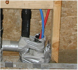
In 'addition to insulation requirements, all domestic hot water pipes that are buried below grade must be installed in a water proof and non-crushable casing or sleeve that allows for installation, removal, and replacement of the enclosed pipe and insulation. Note that the installation show in Figure 5-8 below would not meet the installation requirements since they are not insulated if supplying the kitchen.
Piping exempt from the mandatory insulation requirement includes:
a. Factory installed piping within space conditioning equipment.
b. Piping that penetrates framing members is not required to have insulation where it penetrates the framing. However, if the framing is metal then some insulating material must prevent contact between the pipe and the metal framing.
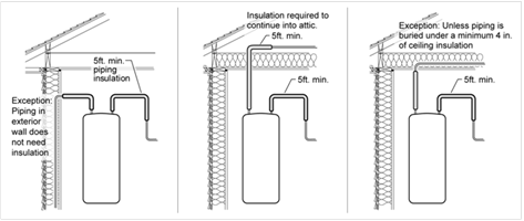
c. Piping located within exterior walls which is installed so that piping is placed inside of wall insulation does not need to be insulated if all the requirements for Insulation Installation Quality are met (See Reference Residential Appendix RA4.4.1).
d. Piping located in the attic does not need pipe insulation if it is continuously buried by at least 4 inches of blown ceiling insulation. Piping may not be placed directly in contact with sheetrock and then covered with insulation to meet this requirement.
e. Piping that serves process loads, gas piping, cold domestic water piping (other than within five feet of the water heater), condensate drains, roof drains, vents, or waste piping.
Other installation information:
a. No insulation should be installed closer than 6 inches from the flue. If possible, bend the pipe away from the flue. Otherwise, it may be necessary to stop pipe insulation short of the storage tank (see 2007 California Mechanical Code, Chapter 3, Table 3-3).
b. All pipe insulation seams should be sealed.
c. Installed piping may not be located in supply or return air plenums. (see 2007 California Mechanical Chapter 3 Table 3-3).
d. Hot and cold water piping, when installed in parallel runs should be a minimum of 2 inches apart. (see RA4).
e. If a fire wall interrupts the first 5 ft of pipe, the insulation may be interrupted at the wall and continued on the other side.
f. Insulation for pipe elbows should be mitered and insulation for tees should be notched. (see RA4).
Standards Table 120.3-A
Where insulation is required as described above, one inch or R-4 insulation is typically required. This requirement applies to domestic hot water pipe (above 105° F) when the pipe diameter is 2 inches or smaller, the water temperature is between 105°F and 200°F, and the insulation conductivity between 0.24 and 0.28 Btu-in/hr-ft²-°F (typical of cellular foam pipe insulation material). One and one half inch insulation is required on pipes greater than 2 inches. For other situations refer to table 120.3-A.
Insulation Protection
If hot water piping insulation is exposed to weather, it must be suitable for outdoor service. For typical cellular foam pipe insulation, this means protection with aluminum, sheet metal, painted canvas, plastic cover, or a water retardant paint coating that shields from solar radiation. Insulation must be protected by an external covering unless the insulation has been approved for exterior use using a recognized federal test procedure.
2. Distribution Systems Serving Multiple Dwelling Units – With Recirculation Loops
Multi-family building may have individual water heaters for each unit, but they are more likely to have a central water heating system with a recirculation loop that supplies each of the units. This recirculation loop is comprised of a supply portion, of larger diameter pipe connected to smaller diameter branches that serve multiple dwelling units, guest rooms, or fixtures and a return portion that completes the loop back to the water heating equipment. The large volume of water which is recirculated during periods of high use creates situations that require the installation of certain controls and servicing mechanisms to optimize performance and allow for lower cost of maintenance. The following paragraphs cover the requirements for system serving multiple dwelling units and with recirculation loops; the corresponding compliance form is CF2R-PLMB-03-E.
a. Air Release Valves
The constant supply of new water in combination with the continuous operation of pump creates the possibility of the pumps cavitation due to air in the water. Cavitation is the formation of bubbles in the low pressure liquid on the suction side of the pump. The cavities or bubbles will collapse when they pass into the higher regions of pressure, causing noise, and vibration, which may lead to damage to many of the components. In 'addition there is a loss in capacity and the pump can no longer build the same head (pressure). Ultimately this impacts the pump’s efficiency and life expectancy.
Cavitation shall be minimized by either the installation of an air release valve or mounting the pump vertically. The air release valve must be located no more than 4 ft from the inlet of the pump. The air release valve must be mounted on a vertical riser with a length of at least 12 inches.
b. Backflow Prevention
Temperature and pressure differences in the water throughout a recirculation system can create potentials for backflows. This can result in cooler water from the bottom of the water heater tank and water near the end of the recirculation loop flowing backwards towards the hot water load and reducing the delivered water temperature.
To prevent this from occurring, the Standards require that a check valve or similar device be located between the recirculation pump and the water heating equipment.
c. Equipment for Pump Priming/Pump Isolation Valves
A large number of systems are allowed to operate until complete failure simply because of the difficulty of repair or servicing. Repair labor costs can be reduced significantly by planning ahead and designing for easy pump replacement when the pump fails. Provision for pump priming and pump isolation valves help reduces maintenance costs.
To meet the pump priming equipment requirement, a hose bib must be installed between the pump and the water heater. In 'addition, an isolation valve shall be installed between the hose bib and the water heating equipment. This configuration will allow the flow from the water heater to be shut off, allowing the hose bib to be used for bleeding air out of the pump after pump replacement.
The requirement for the pump isolation valves will allow replacement of the pump without draining a large portion of the system. The isolation valves shall be installed on both sides of the pump. These valves may be part of the flange that attaches the pump to the pipe. One of the isolation valves may be the same isolation valve as in item C.
d. Connection of Recirculation Lines
Manufacturer’s specifications should always be followed to assure optimal performance of the system. The cold water piping and the recirculation loop piping should never be connected to the hot water storage tank drain port.
e. Backflow Prevention in Cold Water Supply
The dynamic between the water in the heater and the cold water supply are similar to those in the recirculation loop. Thermosyphoning can occur on this side of this loop just as it does on the recirculation side of the system. To prevent this, the Standards require a check valve to be installed on the cold water supply line. The valve should be located between the hot water system and the next closest tee on the cold water supply line. Note that the system shall comply with the expansion tank requirements as described in the California Plumbing Code Section 608.3.

Example 5-1 - Distribution Systems
Question
When I'm insulating the pipes for a recirculating water-heating system, I understand that I must insulate the entire length of hot water pipes that are part of the recirculation loop. Do I also need to insulate the runouts?
Answer
No. Since the water in runouts does not recirculate, they do not need to be insulated.
Example 5-2 - Recirculation system insulation
Question
Can I get pipe insulation credit for a recirculating water-heating system?
Answer
Not for systems serving a single dwelling unit. Recirculating water heating systems have a mandatory insulation requirement for the recirculating section of the hot water pipes; pipes less than 2 inch must be insulated to R-4 and pipes greater than 2 inch need R-6 insulation. For systems serving multiple dwelling units, using R-6 where R-4 is required, and R-8 where R-6 is required, results in credit within the performance approach. All the circulation loop pipes in one location type (e.g., inside, outside, underground) must be insulated to the higher level to qualify.
Example 5-3 - Pipe Insulation
Question
I thought I was supposed to insulate hot and cold water piping from the water heater for either the first 5 ft or the length of piping before coming to a wall, whichever is less. Did I misunderstand?
Answer
Yes. The requirement is that you must insulate the entire length of the first 5 ft, regardless of whether there is a wall (§150.0(j)2). You have two options: (1) interrupt insulation for a fire wall and continue it on the other side of the wall or (2) run the pipe through an insulated wall, making sure that the wall insulation completely surrounds the pipe. The reason for this insulating the cold line requirement is that when heated, the water heater expands and pushes hot water out the cold water line. The first several feet of the cold water pipe near the water heater can be warm and insulation reduces the heat loss from the first 5 feet of the cold water piping.

1. Pipe Insulation
Insulation must meet the level required in the mandatory requirements. Note that pipes buried within ceiling or wall insulation can meet the mandatory requirements. The adopted requirements for installation guidelines are included in RA3 and RA4
2. Heat Tape
If heat tape – electric resistance heating tape wrapped around hot water pipes – may be used only for freeze protection and cannot be used instead of mandatory pipe insulation (see §150.0(j)) or pipe insulation receiving distribution credit.