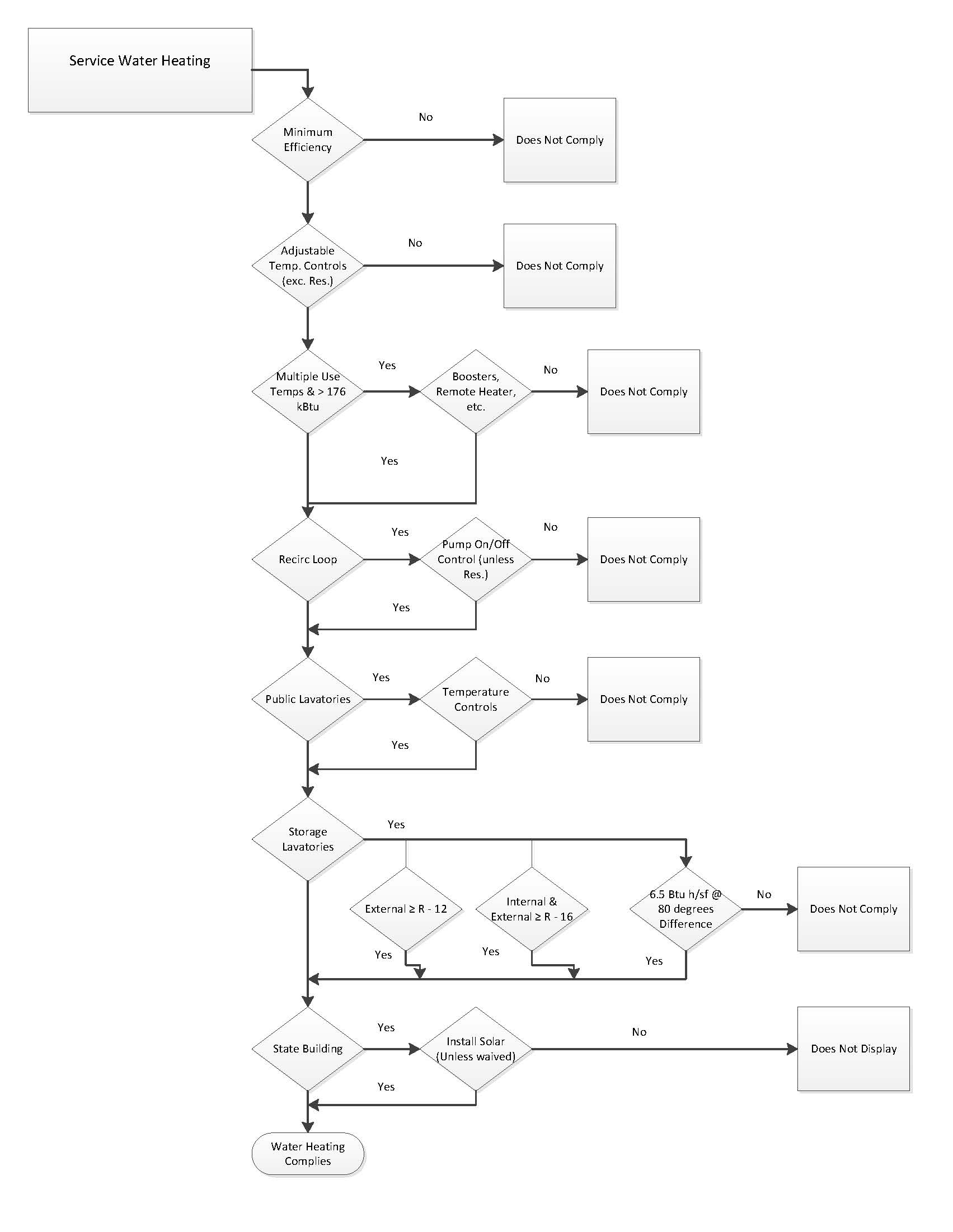
All of the requirements for service hot water that apply to nonresidential occupancies are mandatory measures. There are additional requirements for high-rise residential, hotels and motels which must also comply with the Residential Energy Standards §150.1(c)8 which are described below, as well as in the Residential Compliance Manual.
There are no acceptance requirements for water heating systems or equipment, however, high-rise residential, hotels and motel water heating systems must meet the distribution system eligibility criteria for that portion of the system that is applicable.
4.7.1.1 Efficiency and Control
Any service water heating equipment must have integral automatic temperature controls that allow the temperature to be adjusted from the lowest to the highest allowed temperature settings for the intended use as 'listed in Table 3, Chapter 50 of the ASHRAE Handbook, HVAC Applications Volume.
Service water heaters installed in residential occupancies need not meet the temperature control requirement of §110.3(a)1
4.7.1.2 Multiple Temperature Usage
On systems that have a total capacity greater than 167,000 Btu/h, outlets requiring higher than service water temperatures as 'listed in the ASHRAE Handbook, HVAC Applications Volume shall have separate remote heaters, heat exchangers, or boosters to supply the outlet with the higher temperature. This requires the primary water heating system to supply water at the lowest temperature required by any of the demands served for service water heating. All other demands requiring higher temperatures should be served by separate systems, or by boosters that raise the temperature of the primary supply.
4.7.1.3 Controls for Hot Water Distribution Systems
Service hot water systems with a circulating pump or with electrical heat trace shall include a control capable of automatically turning off the system when hot water is not required. Such controls include automatic time switches, interlocks with HVAC time switches, occupancy sensors, and other controls that accomplish the intended purpose.
4.7.1.4 Public Lavatories
Lavatories in public restrooms must have controls that limit the water supply temperature at the fixtures to 110°F. Where service water heater supplies only restrooms, the heater thermostat may be set to no greater than 110°F to satisfy this requirement; otherwise controls such as automatic mixing valves must be installed.
4.7.1.5 Storage Tank Insulation
Unfired water heater storage tanks and backup tanks for solar water heating systems must have one of the following:
1. External insulation with an installed R-value of at least R-12.
2. Internal and external insulation with a combined R-value of at least R-16.
3. The heat loss of the tank based on an 80 degree F water-air temperature difference shall be less than 6.5 Btu per hour per ft². This corresponds to an effective resistance of R-12.3.
4.7.1.6 Service Water Heaters in State Buildings
High-rise residential buildings constructed by the State of California shall have solar water heating systems. The solar system shall be sized and designed to provide at least 60 percent of the energy needed for service water heating from site solar energy or recovered energy. There is an exception when buildings for which the state architect determines that service water heating is economically or physical infeasible. See the Compliance Options section below for more information about solar water heating systems.
4.7.1.7 Pipe Insulation Thickness
There are updated pipe insulation thickness requirements applicable to nonresidential water heating pipes. For pipes with conductivity ranges within those specified in Table 4-17 of the Standard, the nominal pipe diameters grouping ranges are changed, as well as the thickness of insulation required for each pipe diameter range. The table is repeated below for ease of reference:
|
FLUID TEMPERATURE RANGE |
CONDUCTIVITY RANGE |
INSULATION MEAN RATING TEMPERATURE (°F) |
NOMINAL PIPE DIAMETER (in inches) | |||||||
|
1 and less |
1 to <1.5 |
1.5 to < 4 |
4 to < 8 |
8 and larger | ||||||
|
INSULATION THICKNESS REQUIRED (in inches) | ||||||||||
|
Space heating, Hot Water systems (steam, steam condensate and hot water) and Service Water Heating Systems (recirculating sections, all piping in electric trace tape systems, and the first 8 feet of piping from the storage tank for nonrecirculating systems) | ||||||||||
|
Above 350 |
0.32-0.34 |
250 |
4.5 |
5.0 |
5.0 |
5.0 |
5.0 | |||
|
251-350 |
0.29-0.31 |
200 |
3.0 |
4.0 |
4.5 |
4.5 |
4.5 | |||
|
201-250 |
0.27-0.30 |
150 |
2.5 |
2.5 |
2.5 |
3.0 |
3.0 | |||
|
141-200 |
0.25-0.29 |
125 |
1.5 |
1.5 |
2.0 |
2.0 |
2.0 | |||
|
105-140 |
0.22-0.28 |
100 |
1.0 |
1.5 |
1.5 |
1.5 |
1.5 | |||
|
Space cooling systems (chilled water, refrigerant and brine) | ||||||||||
|
|
Nonres |
Res |
Nonres |
Res |
| |||||
|
40-60 |
0.21-0.27 |
75 |
0.5 |
0.75 |
0.5 |
0.75 |
1.0 |
1.0 |
1.0 | |
|
Below 40 |
0.20-0.26 |
50 |
1.0 |
1.5 |
1.5 |
1.5 |
1.5 | |||
Energy Standards Table 120.3-A
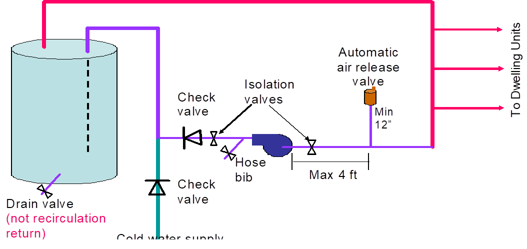
4.7.1.8 Systems with Recirculation Loops
Service water systems that have central recirculation distribution must include all of the following mandatory features. The intent of these measures is to optimize performance and allow for lower cost of maintenance. These requirements are applicable to nonresidential occupancies as well as high-rise residential and hotel/motel systems.
A. Air Release Valves
The constant supply of new water and leaks in system piping or components during normal operation of the pump may introduce air into the circulating water. Entrained air in the water can result in a loss of pump head pressure and pumping capacity, which adversely impacts the pumps’ efficiency and life expectancy. Entrained air may also contribute to increased cavitation.
Cavitation is the formation of vapor bubbles in liquid on the low pressure (suction) side of the pump. The vapor bubbles generally condense back to the liquid state after they pass into the higher pressure side of the pump. Cavitation can contribute to a loss of head pressure and pumping capacity; may produce noise and vibration in the pump; may result in pump impeller corrosion; all of which impacts the pumps’ efficiency and life expectancy.
Entrained air and cavitation should be minimized by the installation of an air release valve. The air release valve must be located no more than 4 ft from the inlet of the pump, and must be mounted on a vertical riser with a length of at least 12 inches. Alternatively, the pump shall be mounted on a vertical section of the return piping.
B. Recirculation Loop Backflow Prevention
Temperature and pressure differences in the water throughout a recirculation system can create potentials for backflows. This can result in cooler water from the bottom of the water heater tank and water near the end of the recirculation loop flowing backwards towards the hot water load and reducing the delivered water temperature.
To prevent this from occurring, the Energy Standards require that a check valve or similar device be located between the recirculation pump and the water heating equipment.
3. Equipment for Pump Priming/Pump Isolation Valves
A large number of systems are allowed to operate until complete failure simply because of the difficulty of repair or servicing. Repair labor costs can be reduced significantly by planning ahead and designing for easy pump replacement when the pump fails. Provision for pump priming and pump isolation valves help reduces maintenance costs.
To meet the pump priming equipment requirement, a hose bib must be installed between the pump and the water heater. 'In addition, an isolation valve shall be installed between the hose bib and the water heating equipment. This configuration will allow the flow from the water heater to be shut off, allowing the hose bib to be used for bleeding air out of the pump after pump replacement.
The requirement for the pump isolation valves will allow replacement of the pump without draining a large portion of the system. The isolation valves shall be installed on both sides of the pump. These valves may be part of the flange that attaches the pump to the pipe. One of the isolation valves may be the same isolation valve as in item C.
4. Connection of Recirculation Lines
Manufacturer’s specifications should always be followed to assure optimal performance of the system. The cold water piping and the recirculation loop piping should never be connected to the hot water storage tank drain port.
5. Backflow Prevention in Cold Water Supply
The dynamic between the water in the heater and the cold water supply are similar to those in the recirculation loop. Thermosyphoning can occur on this side of this loop just as it does on the recirculation side of the system. To prevent this, the Energy Standards require a check valve to be installed on the cold water supply line. The valve should be located between the hot water system and the next closest tee on the cold water supply line. Note that the system shall comply with the expansion tank requirements as described in the California Plumbing Code Section 608.3.
'In 'addition to the mandatory requirements 'listed above, there are mandatory requirements that will apply to water heating systems for hotels, motels and high-rise residential buildings only. All of these requirements are tied to the mandatory requirements in §150.1(c)8 for residential occupancies. Depending on whether the water heating system has a central system or uses individual water heaters will change whether the mandatory features that are 'listed above apply.
4.7.2.1 Storage tank Insulation requirements
For unfired supplemental tanks R-12 must be installed if the internal insulation of the unfired tank is less than R-16.
4.7.2.2 Water piping insulation thickness and conductivity
All domestic hot water system piping conditions listed below, whether buried or not-buried, must be insulated. The insulation thickness and conductivity shall be determined from the fluid temperature range and nominal pipe diameter as required by Table 4-22.
•The first five feet of pipe of hot and cold water from the storage tank must be insulated. In the case of a building with a central distribution system this requirement means that the cold supply line to the central water heater would have to be insulated. For building with central recirculation systems the hot water supply to each unit must be insulated to meet this requirement and the kitchen piping insulation requirement.
•Any pipe in the distribution system that is ¾ inch or larger must be insulated. This includes pipe in the central distribution system and in the distribution system serving the individual units.
•Any piping that is associated with a recirculation loop must be insulated. If the domestic hot water heater system serving the dwelling unit uses any type of recirculation insulation of the entire length of the distribution loop would be required. Insulation would also be required in the case of a dwelling unit with a combined hydronic system that uses any portion of the domestic hot water loop to circulate water for heating. Insulation would not be required on the branches or twig serving the point of use.
•All piping from the heating source to a storage tank or between storage tanks must be insulated.
•All hot water piping from the water heater or source of hot water for each dwelling unit to the kitchen must be insulated.
•All piping buried below grade must be insulated. In addition, all piping below grade must be installed in a waterproof and non-crushable casing or sleeve. The internal cross-section or diameter of the casing or sleeve shall be large enough to allow for insulation of the hot water piping. Pre-insulated pipe with integrated protection sleeve will also meet this requirement.
There are exceptions to the requirements for pipe insulation, as described below:
•In attics and crawlspaces, pipes completely covered with at least 4 inches of insulation are not required to have pipe insulation. Any section of pipe not covered with at least 4 inches of insulation must be insulated.
•In walls, all of the requirements must be met for compliance with Quality Insulatio Installation (QII) as specified in the Reference Residential Appendix RA3.5. Otherwise the section of pipe not meeting the QII specifications must be insulated.
•The last segment of piping that penetrates walls and delivers hot water to the sink or appliance does not require insulation.
•Piping that penetrates framing members shall not be required to have pipe insulation for the distance of the framing penetration. Piping that penetrates metal framing shall use grommets, plugs, wrapping or other insulating material to assure that no contact is made with the metal framing. Insulation shall butt securely against all framing members.
For water heating recirculation systems for high-rise residential and hotel/motel buildings, the code actually references back to the Residential Prescriptive requirements. The following paragraphs recap these requirements.
4.7.3.1 Solar Water Heating
Solar water heating is prescriptively required for water heating systems serving multiple dwelling units, whether it is a motel/hotel or high-rise multifamily building. The minimum solar savings fraction (SSF) is dependent on the climate zone: 0.20 for CZ 1 through 9, and 0.35 for CZ 10 through 16. The Energy Standards do not limit the solar water heating equipment or system type, as long as they are SRCC certified and meet the orientation, tilt and shading requirement specified in RA 4.4. Installation of a solar water heating system exempts multifamily buildings from needing to set aside solar zone for future solar PV installation (§110.10(b)1B). The following paragraphs offer some high-level design considerations for multifamily building solar water heating systems.
A high-priority factor for solar water heating system design is component sizing. Proper sizing of the solar collectors and solar tank ensures that the system take full advantage of the sun’s energy while avoiding the problem of overheating. While the issue of freeze protection has been widely explored (development of various solar water heating system types is a reflection of this evolution), the issue of overheating is often not considered as seriously as it should be. This is especially critical for multifamily-sized systems, due to load variability.
To be conservative, the highest SSF requirement called for by the 2016 Energy Standards is at 35%. Industry standard sizing for an active system is generally 1.5 ft2 collector area per gallon capacity for solar tank. For more detailed guidance and best practices, there are many publicly available industry design guidelines. Two such resources developed by/in association with government agencies are Building America Best Practices Series: Solar Thermal and Photovoltaic Systems , and California Solar Initiative – Thermal: Program Handbook.Because of the new solar water heating requirement and prevalence of recirculation hot water systems in multifamily buildings, it is essential to re-iterate the importance of proper integration between the hot water recirculation system and the solar water heating system. Industry stakeholders recommend the recirculation hot water return to be connected back to the system downstream of the solar storage tank. This eliminates the unnecessary wasted energy used to heat up water routed back from the recirculation loop that may have been sitting in the solar water tank if no draw has occurred over a prolonged period of time.
Another design consideration is the layout and placement of collectors and solar tank. The design should minimize the length of plumbing, thus reduce pipe surface areas susceptible to heat loss and reduce the quantity of piping materials needed for the installation. The distance between collectors and solar tank should also be as short as practically possible.
4.7.3.2 Dual Recirculation Loop Design
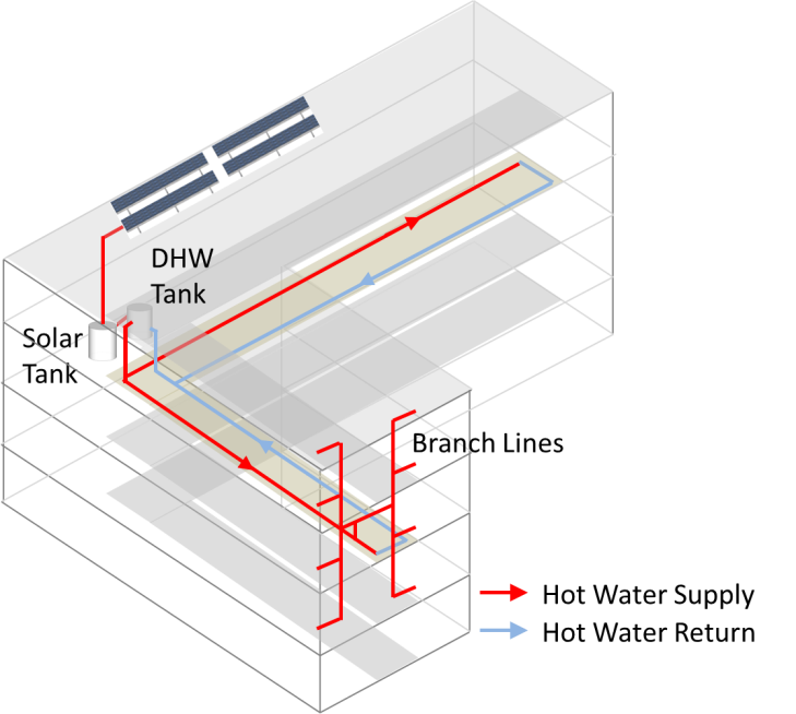
A dual-loop design is illustrated in Figure 4-30. In a dual-loop design, each loop serves half of the dwelling units. According to plumbing code requirements, the pipe diameters can be downsized compared to a loop serving all dwelling units. The total pipe surface area is effectively reduced, even though total pipe length is about the same as that of a single-loop design. For appropriate pipe sizing guidelines, please refer to the Universal Plumbing Code.
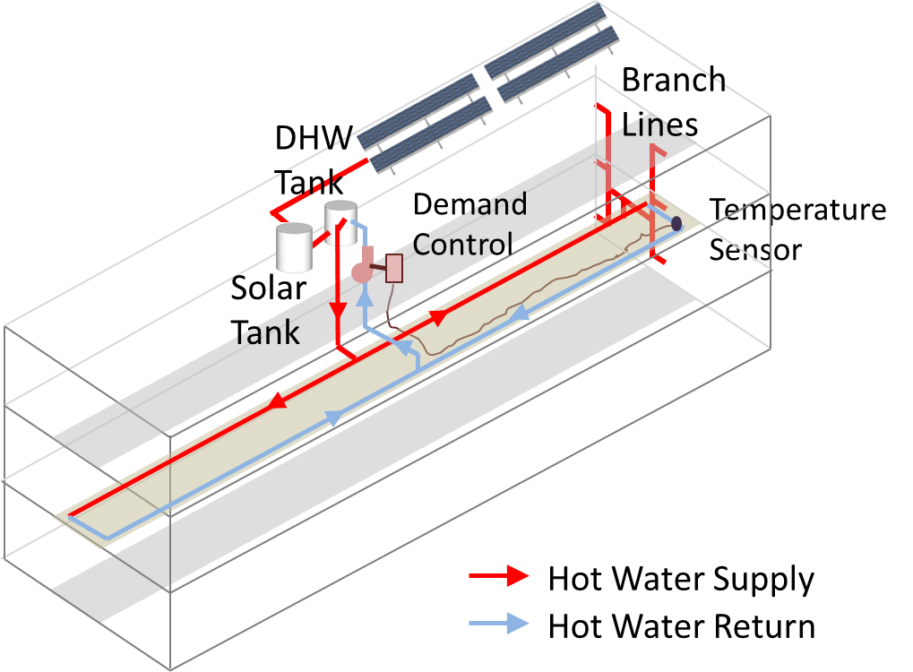
Figure 4-30 provides an example of how to implement dual-loop design in a low-rise multi-family building with a simple layout. In this example, the water heating equipment is located in the middle of top floor with each recirculation loop serving exactly half of the building. The recirculation loops are located in the middle floor to minimize branch pipe length to each of the dwelling units. The Figure 4-30 also illustrates how the solar water heating system and demand control are integrated.
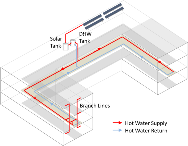
For buildings with complicated layouts, an optimum design for recirculation loops depends on the building geometry. In general, the system should be designed to have each loop serving the equal number of dwelling units in order to minimize pipe sizes. For systems serving buildings with distinct sections, e.g. two wings in an “L” shaped building, it is better to dedicate a separate recirculation loop to each of the sections. Very large buildings and buildings with more than two sections should consider using separate central water heating systems for each section or part of the building. In all cases, a simplified routing of recirculation loops should be used to keep recirculation pipes as short as possible. Figure 4-31 shows examples of dual-loop recirculation system designs in buildings that have complicated floor planes.

Location of water heating equipment in the building should be carefully considered to properly implement the dual-loop design. The goal is to keep overall pipe length as short as possible, as an example, for buildings that do not have complicated floor plans; the designer should consider locating the water heating equipment at the center of the building footprint rather than at one end of the building which helps to minimize the pipe length needed. If a water heating system serves several distinct building sections, the water heating equipment would preferably nest in between these sections.
With the prescriptive solar water heating requirement in the 2016 Energy Standards it is especially important to consider the integration between the hot water recirculation system and the solar water heating system. Based on feedback from industry stakeholders, most solar water heating systems are only configured to operate as a pre-heater for the primary gas water heating equipment. In other words, recirculation hot water returns are usually plumbed back to the gas water heating storage tanks, not directly into the solar tank. This means recirculation loop designs should be mostly based on the building floor plan and are relatively independent of the solar water heating system. Consider that the system’s gas water heating equipment and solar tank should be located close together to avoid heat loss from the piping that connects the two systems. The preferred configuration is to place both the gas water heating equipment and solar tank on the top floor near the solar collector so that the total system pipe length can be reduced. Minimizing pipe length helps to reduce DHW system energy use as well as system plumbing cost.
4.7.3.3 Demand Recirculation Control
The prescriptive requirement for DHW systems serving multiple dwelling units requires the installation of a demand recirculation control to minimize pump operation. Note that demand circulation control is different than the demand control used in single dwelling units. Demand controls for central recirculation systems are based on hot water demand and recirculation return temperatures. The temperature sensor should be installed at the last branch pipe along the recirculation loop.
Any system that does not meet the prescriptive requirements must instead meet the Standard Design Building energy budget or otherwise follow the performance compliance approach.
Pool and spa heating systems must be certified by the manufacturer and 'listed by the Energy Commission as having:
1. An efficiency that complies with the Appliance Efficiency Regulations; and
2. An on-off switch mounted on the outside of the heater in a readily accessible location that allows the heater to be shut-off without adjusting the thermostat setting; and
3. A permanent, easily readable, and weatherproof plate or card that gives instructions for the energy efficient operation of the pool or spa, and for the proper care of the pool or spa water when a cover is used; and
4. No electric resistance heating. The only exceptions are:
a. 'Listed packaged units with fully insulated enclosures and tight fitting covers that are insulated to at least R-6. 'Listed package units are defined in the National Electric Code and are typically sold as self-contained, UL 'Listed spas; or
b. Pools or spas deriving at least 60 percent of the annual heating energy from site solar energy or recovered energy.
If a pool or spa does not currently use solar heating collectors for heating of the water, piping must be installed to accommodate any future installation. Contractors can choose 3 options to allow for the future addition of solar heating equipment:
1. Leave at least 36 inches of pipe between the filter and heater to allow for the future addition of solar heating equipment.
2. Plumb separate suction and return lines to the pool dedicated to future solar heating.
3. Install built-up or built-in connections for future piping to solar water heating. An example of a built-in connection could be a capped off tee fitting between the filter and heater.
Pool and spa heating systems with gas or electric heaters for outdoor use must use a pool cover. The pool cover must be fitted and installed during the final inspection.
All pool systems must be installed with the following:
1. Directional inlets must be provided for all pools that adequately mix the pool water.
2. A time switch or similar control mechanism shall be provided for pools to control the operation of the circulation control system, to allow the pump to be set or programmed to run in the off-peak demand period, and for the minimum time necessary to maintain the water in the condition required by applicable public health standards.
Pool and spa heaters are not allowed to have pilot lights.