4.4.1.1 Requirements for Pipe Insulation
§120.3 and Table 120.3-A
Most piping conveying mechanically heated or chilled fluids for space conditioning or service water heating must be insulated. The required thickness of piping insulation depends on the temperature of the fluid passing through the pipe, the pipe diameter, the function of the pipe within the system, and the insulation’s thermal conductivity.
Table 4-15 specifies the requirements in terms of inches of insulation with conductivity within a specific range. These conductivities are typical for fiberglass or foam pipe insulation. Piping within fan coil units and within other heating or cooling equipment should be insulated based on the pipe diameter and the required value in the table.
Piping that does not require insulation includes the following:
1. Factory installed piping within space-conditioning equipment certified under §110.1 or §110.2, see Section 4.2 of this chapter. Nationally recognized certification programs that are accepted by the Energy Commission for certifying efficiencies of appliances and equipment are considered to meet the requirements for this exception.
2. Piping that conveys fluid with a design operating temperature range between 60 degrees F and 105 degrees F, such as cooling tower piping or piping in water loop heat pump systems.
3. Where the heat gain or heat loss, to or from piping without insulation, will not increase building source energy use. For example, piping connecting fin-tube radiators within the same space would be exempt, as would liquid piping in a split system air conditioning unit.
This exception would not exempt piping in solar systems. Solar systems typically have backup devices that will operate more frequently if piping losses are not minimized.
4. Piping that penetrates framing members shall not be required to have pipe insulation for the distance of the framing penetration. Metal piping that penetrates metal framing shall use grommets, plugs, wrapping or other insulating material to assure that no contact is made with the metal framing.
Conductivities and thicknesses listed in Table 4-15 are typical for fiberglass and foam. When insulating materials are used that have conductivities different from those listed here for the applicable fluid range, such as calcium silicate, Equation 4-1 may be used to calculate the required insulation thickness.
When a pipe carries cold fluids, condensation of water vapor within the insulation material may impair the effectiveness of the insulation, particularly for applications in very humid environments or for fluid temperatures below 40 degrees F. Examples include refrigerant suction piping and low-temperature thermal energy storage (TES) systems. In these cases, manufacturers should be consulted and consideration given to low permeability vapor barriers, or closed-cell foams.
The Energy Standards also require that exposed pipe insulation be protected from damage by moisture, UV and physical abrasion including but not limited to the following:
1. Insulation exposed to weather shall be installed with a cover suitable for outdoor service. The cover shall be water retardant and provides shielding from solar radiation that can cause degradation of the material. Insulation must be protected by an external covering unless the insulation has been approved for exterior use using a recognized federal test procedure. Adhesive tape shall not be used as protection for insulation exposed to weather.
2. Insulation covering chilled water piping and refrigerant suction piping located outside the conditioned space shall have a Class I or Class II vapor retarder. All penetrations and joints of which shall be sealed.
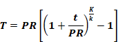
If the conductivity of the proposed insulation does not fall into the conductivity range listed in Table 4-15, the minimum thickness must be adjusted using the following equation:
Equation 4-10 : Insulation Thickness
Where:
T = Minimum insulation thickness for material with conductivity K, inches.
PR = Pipe actual outside radius, inches.
t = Insulation thickness, inches (Table 4-15 for conductivity k).
K = Conductivity of alternate material at the mean rating temperature indicated in Table 4-15 for the applicable fluid temperature range, in Btu-in./(h-ft² -°F).
k = The lower value of the conductivity range listed in Table 4-15 for the applicable fluid temperature, Btu-in/(h-ft² -°F).
|
Fluid Operating Temperature
Range |
Insulation Conductivity |
|
Nominal Pipe Diameter (in inches) |
|||||||||||||||||||||||||
|
Conductivity |
Mean Rating Temperature (°F) |
|||||||||||||||||||||||||||
|
< 1 |
1 to <1.5 |
1.5 to < 4 |
4 to < 8 |
8 and larger |
||||||||||||||||||||||||
|
Space heating and Service Water Heating Systems (Steam, Steam Condensate, Refrigerant, Space Heating, Service Hot Water) |
Minimum Pipe Insulation Required (Thickness in inches or R-value) |
|||||||||||||||||||||||||||
|
Above 350 |
0.32-0.34 |
250 |
Inches |
4.5 |
5.0 |
5.0 |
5.0 |
5.0 |
||||||||||||||||||||
|
R-value |
R 37 |
R 41 |
R 37 |
R 27 |
R 23 |
|||||||||||||||||||||||
|
251-350 |
0.29-0.32 |
200 |
Inches |
3.0 |
4.0 |
4.5 |
4.5 |
4.5 |
||||||||||||||||||||
|
R-value |
R 24 |
R 34 |
R 35 |
R 26 |
R 22 |
|||||||||||||||||||||||
|
201-250 |
0.27-0.30 |
150 |
Inches |
2.5 |
2.5 |
2.5 |
3.0 |
3.0 |
||||||||||||||||||||
|
R-value |
R 21 |
R 20 |
R 17.5 |
R 17 |
R 14.5 |
|||||||||||||||||||||||
|
141-200 |
0.25-0.29 |
125 |
Inches |
1.5 |
1.5 |
2.0 |
2.0 |
2.0 |
||||||||||||||||||||
|
R-value |
R 11.5 |
R 11 |
R 14 |
R 11 |
R 10 |
|||||||||||||||||||||||
|
105-140 |
0.22-0.28 |
100 |
Inches |
1.0 |
1.5 |
1.5 |
1.5 |
1.5 |
||||||||||||||||||||
|
R-value |
R 7.7 |
R 12.5 |
R 11 |
R 9 |
R 8 |
|||||||||||||||||||||||
|
|
Nominal Pipe Diameter (in inches) |
|||||||||||||||||||||||||||
|
< 1 |
1 to <1.5 |
1.5 to < 4 |
4 to < 8 |
8 and larger |
||||||||||||||||||||||||
|
Space cooling systems (chilled water, refrigerant and brine) |
Minimum Pipe Insulation Required (Thickness in inches or R-value)1 |
|||||||||||||||||||||||||||
|
40-60 |
0.21-0.27 |
75 |
Inches |
Nonres 0.5 |
Res 0.75 |
Nonres 0.5 |
Res 0.75 |
1.0 |
1.0 |
1.0 |
||||||||||||||||||
|
R-value |
Nonres R 3 |
Res R 6 |
Nonres R 3 |
Res R 5 |
R 7 |
R 6 |
R 5 |
|||||||||||||||||||||
|
Below 40 |
0.20-0.26 |
50 |
Inches |
1.0 |
1.5 |
1.5 |
1.5 |
1.5 |
||||||||||||||||||||
|
R-value |
R 8.5 |
R 14 |
R 12 |
R 10 |
R 9 |
|||||||||||||||||||||||
|
Footnote to Table 120.3-A: These thickness are based on energy efficiency considerations only. Issues such as water vapor permeability or surface condensation sometimes require vapor retarders or additional insulation. |
| |||||||||||||||||||||||||||
Source: California Energy Commission, Building Energy Efficiency Standards, Table 120.3-A
Example 4-19
Question
What is the required thickness for calcium silicate insulation on a four inch diameter pipe carrying a 300 degree F fluid?
Answer
From Table 4-15, using data for 300 degree F fluid:
PR = 2"
t = 4.5" (from the table for a 4 inch pipe with 300 degree F fluid)
K = 0.40 (Btu-in.)/(h-ft²-°F) (from calcium silicate insulation manufacturer’s conductivity data at 200 degree F)
k = 0.29 (Btu-in.)/(h-ft²-°F) (the lower value of the range for conductivity for 300 degree F fluid)
T = PR[(1 + t/PR)K/k – 1]
T = 2[(1 + 4.5/2)(0.40/0.29)– 1]
T = 8.2 inches
When insulation is not available in the exact thickness calculated, the installed thickness should be the next larger available size.
4.4.1.2 Requirements for Air Distribution System Ducts and Plenums
Poorly sealed or poorly insulated duct work can cause substantial losses of air volume and energy. All air distribution system ducts and plenums, including building cavities, mechanical closets, air handler boxes and support platforms used as ducts or plenums, are required to be in accordance with the California Mechanical Code Sections 601, 602, 603, 604, 605 and ANSI/SMACNA-006-2006 HVAC Duct Construction Standards - Metal and Flexible, 3rd Edition.
Healthcare facilities are exempt from §120.4 and shall comply with the applicable requirements of the California Mechanical Code.
A. Installation and Insulation
Portions of supply-air and return-air ducts or ductwork conveying heated or cooled air shall be insulated to a minimum installed level of R-8 when installed:
1. Outdoors
2. In a space between the roof and an insulated ceiling
3. In a space directly under a roof with fixed vents or openings to the outside or unconditioned spaces
4. In an unconditioned crawlspace
5. In other unconditioned spaces
Portions of supply-air ducts ductwork that are not in one of the above spaces shall be insulated to a minimum installed level of R-4.2 or be exposed in a directly conditioned space. For example, supply-air ducts that are inside the thermal envelope but concealed from view (such as ducts in a chase or above a hard or T-bar ceiling) are required to be insulated with at least R-4.2. However, if the ducts are exposed to directly conditioned space (i.e. ducts are visible to the occupants), then no insulation would be required.
Requirements of the California Mechanical Code
1. Mechanically fasten connections between metal ducts and the inner core of flexible ducts.
2. Joint and seal openings with mastic, tape, aerosol sealant or other duct closure system that meets the applicable requirements of UL 181, UL 181A, UL 181B or UL 723 (aerosol sealant).
All joints must be made airtight by use of mastic, tape, aerosol sealant, or other duct-closure system that meets the applicable requirements of UL 181, UL 181A, UL 181B, or UL 723. Duct systems shall not use cloth-back, rubber adhesive duct tape regardless of UL designation, unless it is installed in combination with mastic and clamps.
When mastic or tape is used to seal openings greater than 1/4 inch, a combination of mastic and mesh or mastic and tape must be used.
The Energy Commission has approved two cloth-backed duct tapes with special butyl or synthetic adhesives rather than rubber adhesive to seal flex duct to fittings. These tapes are:
1. Polyken 558CA or Nashua 558CA, manufactured by Berry Plastics, Tapes and Coatings Division; and
2. Shurtape PC 858CA, manufactured by Shurtape Technologies, Inc.
These tapes passed Lawrence Berkeley National Laboratory tests comparable to those that cloth-back rubber-adhesive duct tapes failed (the Lawrence Berkeley National Laboratory test procedure has been adopted by the American Society of Testing and Materials as ASTM E2342-03). These tapes are allowed to be used to seal flex ducts to fittings without combination with mastic. These tapes cannot be used to seal other duct system joints, such as the attachment of fittings to plenums and junction boxes. On their backing, these tapes have the phrase "CEC Approved," and a drawing of a fitting to plenum joint in a red circle with a slash through it (the international symbol of prohibition) to illustrate where they are not allowed to be used. Installation instructions in the box explains how to install the tape on duct core to fittings and a statement that the tape cannot be used to seal fitting to plenum and junction box joints.
Factory-Fabricated Duct Systems
Factory-fabricated duct systems must meet the following requirements:
1. All factory-fabricated duct systems shall comply with UL 181 for ducts and closure systems, including collars, connections and splices, and be labeled as complying with UL181. UL181 testing may be performed by UL laboratories or a laboratory approved by the Executive Director.
2. Pressure-sensitive tapes, heat-activated tapes, and mastics used in the manufacture of rigid fiberglass ducts comply with UL 181 and UL181A.
3. Pressure-sensitive tapes and mastics used with flexible ducts comply with UL181 and UL181B.
4. Joints and seams of duct systems and their components shall not be sealed with cloth back rubber adhesive duct tapes unless such tape is used in combination with mastic and drawbands.
Field-Fabricated Duct Systems
Field-fabricated duct systems must meet the following requirements:
1. Factory-made rigid fiberglass and flexible ducts for field-fabricated duct systems comply with UL 181. Pressure-sensitive tapes, mastics, aerosol sealants or other closure systems shall meet applicable requirements of UL 181, UL 181A and UL 181B.
2. Mastic Sealants and Mesh:
a. Sealants comply with the applicable requirements of UL 181, UL 181A, and UL 181B, and shall be non-toxic and water resistant.
b. Sealants for interior applications shall pass ASTM C 731(extrudability after aging) and D 2202 (slump test on vertical surfaces), incorporated herein by reference.
c. Sealants for exterior applications shall pass ASTM C 731, C 732 (artificial weathering test) and D 2202, incorporated herein by reference.
d. Sealants and meshes shall be rated for exterior use.
3. Pressure-sensitive tapes shall comply with the applicable requirements of UL 181, UL 181A and UL 181B.
4. Drawbands used with flexible duct shall:
a. Be either stainless-steel worm-drive hose clamps or UV-resistant nylon duct ties.
b. Have a minimum tensile strength rating of 150 lbs.
c. Be tightened as recommended by the manufacturer with an adjustable tensioning tool.
5. Aerosol-Sealant Closures.
a. Aerosol sealants meet applicable requirements of UL 723 and must be applied according to manufacturer specifications.
b. Tapes or mastics used in combination with aerosol sealing shall meet the requirements of this section.
6. Joints and seams of duct systems and their components shall not be sealed with cloth back rubber adhesive duct tapes unless such tape is used in combination with mastic and drawbands.
Duct Insulation R-Values
Since 2001, the Energy Standards have included the following requirements for the labeling, measurement and rating of duct insulation:
1. Insulation R-values shall be based on the insulation only and not include air-films or the R-values of other components of the duct system.
2. Insulation R-values shall be tested C-values at 75 degrees F mean temperature at the installed thickness, in accordance with ASTM C 518 or ASTM C 177.
3. The installed thickness of duct insulation for purpose of compliance shall be the nominal thickness for duct board, duct liner, factory made flexible air ducts and factory-made rigid ducts. For factory-made flexible air ducts, the installed thickness shall be determined by dividing the difference between the actual outside diameter and nominal inside diameter by two.
4. The installed thickness of duct insulation for purpose of compliance shall be 75 percent of its nominal thickness for duct wrap.
5. Insulated flexible air ducts must bear labels no further than three feet apart that state the installed R-value (as determined per the requirements of the Energy Standards).
A typical duct wrap, nominal 1-1/2 inches and 0.75 pound per cubic foot will have an installed rating of R-4.2 with 25 percent compression.
Protection of duct Insulation
The Energy Standards require that exposed duct insulation be protected from damage by moisture, UV and physical abrasion including but not limited to the following:
1. Insulation exposed to weather shall be suitable for outdoor service; e.g., protected by aluminum, sheet metal, painted canvas, or plastic cover. Insulation must be protected by an external covering unless the insulation has been approved for exterior use using a recognized federal test procedure.
2. Cellular foam insulation shall be protected as above or painted with a coating that is water retardant and provides shielding from solar radiation that can cause degradation of the material.
Example 4-20
Question
What are the sealing requirements in a VAV system having a static pressure set point of 1.25 inches water gauge and a plenum return?
Answer
All duct work located within the return plenum must be sealed in accordance with the California Mechanical Code Sections 601, 602, 603, 604, 605 and ANSI/SMACNA-006-2006 HVAC Duct Construction Standards Metal and Flexible 3rd Edition (refer to §120.4 ). Pressure-sensitive tape, heat-seal tape and mastic may be used, if it meets the applicable requirement of UL 181, 181A, 181B, to seal joints and seams which are mechanically fastened per the California Mechanical Code.
Each of these applicable prescriptive requirements must be met. If one or more applicable requirements cannot be met, the performance method may be used as explained in Chapter 11.
4.4.2.1 Duct Leakage
Systems serving nonresidential buildings, including high-rise residential and hotel/motel guest rooms, shall have their ducts sealed when certain criteria are met. Healthcare facilities are exempt from §140.4(l) and shall comply with the applicable requirements of the California Mechanical Code.
Ducts that are part of small single zone systems with portions of the ductwork either outdoors or in uninsulated or vented ceiling spaces are required to be sealed and leak tested as specified in Reference Nonresidential Appendix NA1. This will generally only apply to small commercial projects that are one or two stories with packaged single zone units or split systems. Duct leakage testing only applies when all of the following are true:.
1. The system is constant volume, single zone, and serves an occupiable space.
2. The system serves less than 5,000 sq ft of conditioned floor area.
3. The system ductwork has 25 percent or more of the duct surface area located outdoors, in unconditioned space, in a ventilated attic, or a crawl space; where the U-factor of the roof is greater than the U-factor of the ceiling, or where the roof does not meet the requirements of §140.3(a)1B.
Where duct sealing and leakage testing is required, the ducts must be tested by a HERS certified agency to demonstrate a leakage rate of no more than 6 percent of the nominal supply fan flow.
Alterations to an existing space conditioning system may trigger the duct sealing requirement. For more information, see Section 4.9.4.3.
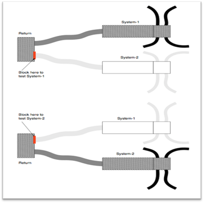
A. Duct Leakage Testing for Multiple Duct Systems With Common Return Ducts
If there are two or more duct systems in a building that are tied together at a common return duct, then each duct system should be tested separately, including the shared portion of the return duct system which should be included in each system test. Under this scenario, the portions of the second duct system that is not being tested must be completely isolated from the portions of the ducts that are being tested, so the leakage from the second duct system does not affect the leakage rate from the side that is being tested.
The diagram below represents the systems that are attached to a shared return boot or remote return plenum. In this case, the point in the return system that needs to be blocked off is readily accessible through the return grille.
The “duct leakage averaging” method where both systems are tested together (as though it is one large system) and the results divided by the combined tonnage to get the target leakage may not be used as it allows a duct system with more the 6 percent leakage to pass if the combined system’s leakage is 6 percent or less.
Figure 4-12: Example of Two Duct Systems with a Common Return
Example 4-21
Question
A new 20-ton single zone system with new ductwork serving an auditorium is being installed. Approximately half of its ductwork is on the roof. Does it need to be leak tested?
Answer
Probably not. Although this system meets the criteria of being single zone and having more than 25 percent of the duct surface area on the roof, the unit probably serves more than 5,000 sq ft of space. Most 15- and 20-ton units will serve spaces that are significantly larger than 5,000 sq ft. If the space is 5,000 sq ft or less the ducts do need to be leak tested per §140.4(l).
Example 4-22
Question
A new 5-ton single zone system with new ductwork serving a 2,000 sq ft office is being installed. The unit is a down discharge configuration and the roof has insulation over the deck. Does the ductwork need to be leak tested?
Answer
Probably not. Although this system meets the criteria of being single zone and serving less than 5,000 sq ft of space, it does not have 25 percent of its duct area in one of the spaces listed in §140.4(l). With the insulation on the roof and not on the ceiling, the plenum area likely meets the criteria of indirectly conditioned so no leakage testing is required.
The Energy Standards have acceptance requirements where duct sealing and leakage testing is required by §140.4(l).
These tests are described in the Chapter 13, Acceptance Requirements and the Reference Nonresidential Appendix NA7.