
The values in this appendix must be used for all residential and nonresidential prescriptive compliance calculations. California Energy Commission approved compliance software may make adjustments to the values in these tables using procedures described in this appendix.
The data tables are organized first by roofs, walls, and floors. For each, the data is further organized by construction type, beginning with wood framed construction, followed by metal framed construction, concrete and special construction assemblies. Each table features a letter/number coordinate system (shaded in gray) that can be used as an identifier for each value, i.e. 4.2.1-A10 indicates Table 4.2.1, Column A, Row 10. Construction assembly descriptions shall be concatenated first by row and then by column. For example, the descriptions of 4.2.1.-A20 and 4.3.1-H3 and shall be as follows (abbreviations are acceptable):
Wood Framed Attic, Trusses@24 inch. OC, R-30 attic
insulation, No
continuous insulation
Wood Framed Wall, Wd 2x4 @16 inch OC, R-13 cavity
insulation, R-14 continuous insulation
The R-value representing the component(s) of a construction assembly may be rounded to the nearest whole R-value. If a construction assembly is not adequately represented in the tables below, the permit applicant or the manufacturer of the product may request the California Energy Commission approve alternative U-factors for the construction assembly. The California Energy Commission Executive Director will grant such approval, after reviewing submittals and supporting information from the applicant and the merits of the information to support the intended use. Acceptable calculation methods for determining a construction component’s R-value or overall assembly U-factor are based on ASHRAE Handbook of Fundamental procedures, such as:
(a) Testing: Guarded Hot Plate (ASTM C177)
Heat Flow Meter (ASTM C518)
Hot Box Apparatus (ASTM C1363)
(b) Series/Parallel Path Calculation Method for wood framed assemblies of roof/ceilings, walls (above and below grade), and floors.
(c) Modified Zone Method for roof/ceilings, walls, and floor constructions that have metal framing.
New component(s) of a construction assembly approved by the Executive Director will be published as an addendum to this appendix for use by all compliance authors. Addenda may consist of new tables or additional rows or columns to existing tables.
California Energy Commission approved software used for performance or prescriptive calculations may make adjustments to the data contained in this appendix to account for the special circumstances of particular constructions. This section defines the rules for making these adjustments. These adjustments may not be made when the tables are used manually. Software may have input screens where the user may choose a construction by entering the cavity insulation (or insulation penetrated by framing); the continuous insulation; and other factors such as framing spacing. To the software user, the process of using these tables may look very much like a traditional U-factor calculation.
JA4.1.2.1 Determining R-value and U-factor of Construction Assemblies
The installer shall provide documentation from the manufacturer supporting the installed R-value. Some products have R-value markings, others do not. For site applied insulation (i.e., loose-fill glass fiber and mineral fiber, cellulose, and spray polyurethane foam insulation), the insulation shall be installed in comformance to the manufacturer’s coverage chart, R-value chart, or similar performance data sheet.
Data presented in the tables is not inclusive of all materials or combinations of materials used in construction of residential and nonresidential buildings. Information presented for framed and nonframed assemblies provides a summary of the reference assembly components representing the R-value and U-factor necessary for determining prescriptive compliance with the Standards. This data is also used by approved compliance software to establish the required thermal efficiencies affecting energy use for the standard design building in performance compliance calculations.
R-value is used to describe insulation effectiveness, but R-value does not describe the overall performance of the complete assembly. Construction assemblies usually have more than one layer and each layer has its own conductance, or rate of heat transfer. The U-factor more fully describes the conductance of every component of the construction assembly.
The prescriptive compliance table values for framed and nonframed assemblies of wood and steel roof and ceilings, walls, and floors are developed from series and parallel path procedures of the American Society of Heating, Refrigerating and Air-Conditioning Engineers, Inc. (ASHRAE). Approved computer software uses more detailed calculations and must be used for all buildings using mass type construction. Prescriptive compliance can be demonstrated when the insulation’s R-value is equal to or greater than the R-value required for the envelope feature in the climate zone which the building is permitted for construction; or has an overall U-factor equal to or less than the U-factor required for the envelope feature in the climate zone which the building is permitted for construction.
For example, the R-value and U-factor of components within assemblies of wood framing that are not represented in the tables can be calculated using the procedure shown below (i.e., substituting for different components). For example, R-values of different insulation types can be inserted into Table 4.1.1 and the assembly’s overall R-value and U-factor can be determined. Each layer of the assembly is entered in sequence at a cross-section through its cavity, from outside to inside.
For more advanced assemblies, and for steel framed assemblies, within the California Building Code Compliance software (CBECC) for both residential and nonresidential buildings, the Energy Commission has developed an assembly calculator to automate ASHRAE procedures in order to help the building community in calculating R-values and U-factors of wood and metal framed assemblies with a higher degree of accuracy and speed. The output forms of this program can be used as part of a residential or nonresidential building permit submittal.
|
Assembly Type: Wall 2x4 16 in. o.c |
R-Value |
Assembly U-Factor |
|
|
Framing Material: Wood |
|||
|
Assembly Components |
Cavity (Rc) |
Frame (Rf) |
|
|
Outside air film |
0.17 |
0.17 |
|
|
3/8 inch 2-coat stucco |
0.08 |
0.08 |
|
|
1 inch, R-4 EPS insulating sheathing |
4.0 |
4.0 |
|
|
Building paper (felt) |
0.06 |
0.06 |
|
|
R-15 insulation |
15 |
-- |
|
|
2x4 inch doug fir framing @ R-0.99 per inch |
-- |
3.47 |
|
|
0.50 inch gypsum board |
0.45 |
0.45 |
|
|
Inside air film |
0.68 |
0.68 |
|
|
Subtotal |
20.44 |
8.91 |
|
|
1/RcX (1–(Frame% / 100))]+[(1/Rf)X(Frame% / 100)] [(1/20.44) X ( 1- (25/100))] + [(1/8.91) X (25/100)] |
|||
|
0.065 |
|||
[ 1/Rc x (1 – (Frame% / 100)) ] + [ (1/Rf) x (Frame% / 100) ] = Assembly U-Factor
Where: Frame percentage (%) determined by Table 4.1.6
JA4.1.2.2 Accounting for Continuous Insulation R-value
Many of the tables in this appendix have columns for varying levels of continuous insulation. Continuous insulation is insulation that is uninterrupted by framing and provides a continuous insulating layer. Limits on the position of the continuous insulation and other factors are specified in each table. When data from a table is used manually, the R-value of the continuous insulation in the proposed construction shall be equal to or greater than the R-value shown in the column heading; no interpolation is permitted. California Energy Commission approved software used for performance or prescriptive calculations may account for any amount of continuous insulation using Equation 4-1. This adjustment may not be used, however, for continuous insulation with thermal resistance less than R-2.
Where:
UWith.Cont.Insul Calculated U-factor of the construction assembly with a specific R-value of continuous insulation.
UCol.A A U-factor selected from column A.
RCont.Insul The R-value of continuous insulation.
If insulation layers are added that are interrupted by furring strips, then the effective R-values from Table 4. 3.13 shall be used in Equation 4-1.
JA4.1.2.3 Accounting for Unusual Construction Layers
The assumptions that are the basis of the U-factors published in this appendix are documented in the paragraphs following each table. California Energy Commission approved software used for prescriptive or performance calculations may be used to make adjustments to these assumptions based on data entered by the software user. Adjustments may only be made, however, when the total R-value of the proposed construction is at least an R-2 greater than the documented assumption. Each table includes the assumptions used to determine the U-factors.
Equation 4-2 shall be used to make these adjustments.
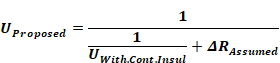
Where:
UProposed Calculated U-factor of the proposed construction assembly.
UWith.Cont.Insul The U-factor adjusted for continuous insulation using Equation 4-1.
∆RAssumed The difference in R-value between what was assumed in the table and the proposed construction for a continuous layer.
There are limits, however, on the types of adjustments that can be made.
(a) The difference in resistance shall be at least R-2. When calculating the difference in R-value, no changes in assumptions shall be made to the framing/insulation layer; the proposed construction shall assume the same values as the table.
(b) The thermal resistance of air layers shall be taken from the 2009 ASHRAE Handbook of Fundamentals, for a mean temperature of 50°F, a temperature difference of 20 °F and an effective emittance of 0.82.
(c) R-values for air layers for roof and ceiling assemblies shall be based on heat flow up. R-values for air layers for floor assemblies shall be based on heat flow down. R-values for other assemblies shall be based on horizontal heat flow. Air layers must be sealed on edges to prevent air layer mixing with ambient air.
(d) One additional air gap may be credited, but not air gaps that are within the framing insulation cavity layer; these are already accounted for in the published data. Air gaps of less than 0.5 inch thickness shall be considered to have an R-value of zero. An example of an acceptable additional air gap would be the space between a brick veneer and the sheathing on the framed wall.
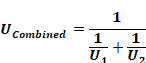
JA4.1.2.4 Double Walls
The U-factor of double walls or other double assemblies may be determined by combining the U-factors from the individual construction assemblies that make up the double wall. The following equation shall be used.
Equation 4-3
If continuous roof insulation is tapered for drainage or other purposes, then the user may determine the overall U-factor in one of two ways:
(a) To determine the U-factor for the roof at the location where the insulation is at a minimum and where it is at a maximum. Take the average of these two U-factors. With the R-value compliance approach (prescriptive method only), calculate the R-value as the inverse of the average U-factor as determined above. R-values may not be averaged.
(b) Divide the roof into sub-areas for each one-inch increment of insulation and determine the U-factor of each sub-area. This approach may only be used with the performance method, and in this case, each sub area shall be modeled as a separate surface.
When roofs have a drain located near the center and when tapered insulation creates a slope to the drain, the surface area at the maximum insulation thickness will be significantly greater than the surface area at the minimum thickness, so the second method will give a more accurate result. The first method yields a conservative estimate for roofs with central drains.
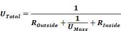
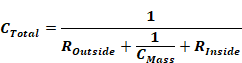
The data in Table 4.3.14 may be used to modify the U-factors and C-factors from Table 4.3.5, Table 4.3.6, and Table 4.3.7 when an additional layer is added to the inside or outside of the mass wall. For exterior insulation finish systems (EIFS) or other insulation only systems, values should be selected from row 26 of Table 4.3.14 In these cases, the R-value of the layer is equal to the R-value of the insulation. The other choices from this table represent systems typically placed on the inside of mass walls. The following equations calculate the total U-factor or C-factor, where Umass and Cmass are selected from Table 4.3.5, Table 4.3.6, or Table 4.3.7 and ROutside and RInside are selected from Table 4.3.14. Routside is selected from row 26 while Rinside is selected from rows 1 through 25.
Equation 4-4
Equation 4-5
The values from Table 4.3.14 may be used to modify the U-factors of other construction assemblies as well, when non-homogeneous layers are added (see Equation 4-1).
For the purpose of calculations for the Joint Appendices plywood, particle board, oriented strand board (OSB) and similar sheathing materials will all be considered Wood Based Sheathing. A single R-value will be used for each thickness listed regardless of the material. This approach simplifies calculations yet has little effect on the overall R-value of assemblies since the differences in sheathing R-value are minimal compared to the overall assembly.
R-values for Wood Based Sheathing
|
Thickness |
R-value (ft2-hr oF/Btu) |
|
3/8 inch |
0.36 |
|
1/2 inch |
0.48 |
|
5/8 inch |
0.60 |
|
3/4 inch |
0.72 |
|
1 inch |
0.96 |
|
1 1/4 inch |
1.20 |
The thermal resistance of framed assemblies is dependent on the assembly’s total R-value, and the quality of construction to limit air intrusion within the assembly that can rob the insulation of its effectiveness. A given assembly type is made of several individual layers and components, each having specific resistance values. However, the assembly’s R-value and overall U-factor is primarily affected by: (1) the R-value of insulation installed within the cavity, (2) the R-value of continuous insulating sheathing added to the interior or exterior face of the framing, and, (3) the amount of framing that interrupts the plane of insulation separating conditioned from unconditioned space. All framed assemblies shall include the framing percentages indicated in Table 4.1.6.
Advanced wall systems (AWS) reduce the amount of material required for wall framing which increases the insulation within the cavity by:
(a) Use of 24” oc framing
(b) Eliminating intermediate framing for cripple and king studs
(c) Use of single top plates
(d) Use of double stud corners
(e) Use of in-line (i.e., stack) framing to maintain continuity of transferring live loads of roof framing to wall framing, allowing roof sheathing and exterior siding to be installed at full widths
(f) Reducing framing for connections at interior partition walls (i.e., T-walls)
(g) Reducing window and door header size
|
Assembly Type |
Framing Spacing |
Framing Percentage |
|
Walls |
16"o.c. |
25 % |
|
24"o.c. |
22 % |
|
|
48"o.c. 24” o.c. |
4 % 17% |
|
|
AWS |
||
|
Walls Metal |
16"o.c. |
15% |
|
24"o.c. |
12% |
|
|
Floors |
16"o.c. |
10 % |
|
24"o.c. |
7 % |
|
|
Roofs |
16"o.c. |
10 % |
|
24"o.c. |
7 % |
|
|
48"o.c |
4 % |
These procedures apply to two types of SPF used as building insulation: medium-density closed cell SPF (ccSPF) and low-density open cell SPF (ocSPF).
(a) ccSPF: A spray applied polyurethane foam insulation having a closed cellular structure resulting in an installed nominal density of 1.5 to less than 2.5 pounds per cubic foot (pcf).
R-value: The total R-value shall be calculated based on the nominal required thickness of the insulation multiplied by an R-value of 5.8 per inch. The R-value of ccSPF insulation shall meet or exceed the installed thickness specified in Table 4.1.7.
Alternatively, the total R-value may be calculated based on the thickness of insulation multiplied by the "tested R-value per inch" as 'listed in the Table of R-values or R-value Chart from the manufacturer's current ICC Evaluation Service Report (ESR) that shows compliance with Acceptance Criteria for Spray-Applied Foam Plastic Insulation--AC377. Based on this calculation, the overall assembly U-factor shall be determined by selecting the assembly that matches the assembly type, framing configuration, and cavity insulation from the appropriate Reference Joint Appendix JA4 table or other approved method specified in Section JA4 of the Reference Appendices.
The R-value of the installed insulation shall be based on the verified thickness at an R-value of 5.8 per inch unless an ESR is provided with compliance documentation that verifies use of other values. Approved compliance software shall make appropriate adjustments to account for the R-value and U-factor effects of the ccSPF assembly.
Nominal Thickness: ccSPF sprayed into framed cavities or on flat surfaces will expand with variable thicknesses, visibly appearing as undulations on the surface of the insulation. The average thickness of the foam insulation must meet or exceed the required R-value. Depressions in the foam insulation’s surface shall not be greater than 1/2-inch of the required thickness at any given point of the surface area being insulated.
Filling of Framed Assemblies: ccSPF insulation is not required to fill the cavities of framed assemblies provided the installed thickness of insulation conforms to compliance documentation and that the bottom and top plates of vertical framing and both ends of horizontal framing, including band and rim joists, are sprayed to completely fill the cavity adjacent to and in contact with the framing to a distance of 2.0 inches away from the framing for ocSPF insulation, or filled to the thickness meeting ASTM testing as an air barrier.
Air Barrier: ccSPF installed as an air barrier shall be a minimum of 2.0 inches in thickness; alternatively, ccSPF insulation shall be installed at a thickness that meets an air permeance no greater than 0.02 L/s-m2 at 75 Pa pressure differential when tested in accordance to ASTM E2178 or ASTM E283.
(b) ocSPF: A spray applied polyurethane foam insulation having an open cellular structure resulting in an installed nominal density of 0.4 to less than 1.5 pounds per cubic foot (pcf).
R-value: The total R-value shall be calculated based on the nominal required thickness of the insulation multiplied by an R-value of 3.6 per inch. The R-value of ocSPF insulation shall meet or exceed the installed thickness specified in Table 4.1.7.
Alternatively, the total R-value may be calculated based on the thickness of insulation multiplied by the "tested R-value per inch" as 'listed in the Table of R-values or R-value Chart from the manufacturer's current ICC Evaluation Service Report (ESR) that shows compliance with Acceptance Criteria for Spray-Applied Foam Plastic Insulation--AC377. Based on this calculation, the overall assembly U-factor shall be determined by selecting the assembly that matches the assembly type, framing configuration, and cavity insulation from the appropriate Reference Joint Appendix JA4 table or other approved method specified in Section JA4 of the Reference Appendices.
The R-value of the installed insulation shall be based on the verified thickness at an R-value of 3.6 per inch unless an ESR is provided with compliance documentation that verifies use of other values. Approved compliance software shall make appropriate adjustments to account for the R-value and U-factor effects of the ocSPF assembly.
Nominal Thickness: ocSPF sprayed into framed cavities or on flat surfaces will expand with variable thicknesses, visibly appearing as undulations on the surface of the insulation. The average thickness of the foam insulation must meet or exceed the required R-value. Depressions in the foam insulation surface shall not be greater than 1-inch of the required thickness provided these depressions do not exceed 10% of the surface area being insulated.
Filling of Framed Assemblies: ocSPF insulation shall completely fill cavities of 2x4 inch framing or less. Cavities greater than 2x4 inch framing dimensions may be filled to the thickness that meets the required R-value used for compliance provided that the bottom and top plates of vertical framing and both ends of horizontal framing, including band and rim joists, are sprayed to completely fill the cavity adjacent to and in contact with the framing to a distance of 5.5 inches away from the framing for ocSPF insulation, or filled to the thickness meeting ASTM testing as an air barrier.
Air Barrier: ocSPF installed as an air barrier shall be a minimum of 5.5 inches in thickness; alternatively, ocSPF insulation shall be installed at a thickness that meets an air permeance no greater than 0.02 L/s-m2 at 75 Pa pressure differential when tested in accordance to ASTM E2178 or ASTM E283.
|
Equivalent R-Values for SPF insulation |
11 |
13 |
15 |
19 |
21 |
22 |
25 |
30 |
38 |
|
Required thickness of ccSPF Insulation @ R5.8/inch |
2.00 |
2.25 |
2.75 |
3.50 |
3.75 |
4.00 |
4.50 |
5.25 |
6.75 |
|
Required thickness of ocSPF insulation @ R3.6/inch |
3.0 |
3.5 |
4.2 |
5.3 |
5.8 |
6.1 |
6.9 |
8.3 |
10.6 |
NOTE:
A HERS rater shall verify the installation of SPF insulation using the procedures specified in RA3.5.5 whenever R-values other than the default R-value per inch 'listed in Table 4.1.7 are used for compliance (see "R-value" in sections RA3.5.5.0.1(a) and RA3.5.5.0.1(b)).