
Some residential projects may not wish to use or do not meet the requirements for prescriptive compliance. The performance approach offers increased flexibility as well as compliance credits for certain assemblies, usually those requiring HERS verification. The designs described below are examples of residential envelope strategies that can be implemented under the performance approach. The proposed design used under the performance approach is compared to the standard design, which is determined by the prescriptive requirements. Remember that when using the performance approach, all applicable mandatory measures must still be met.
Advanced Assemblies. Common strategies for exceeding the minimum energy performance level set by the 2019 Energy Standards include the use of better components such as:
•Higher insulation levels.
•More efficient fenestration.
•Reducing building infiltration.
•Use of cool roof products.
•Better framing techniques (such as the use of raised-heel trusses that accommodate more insulation).
•Reduced thermal bridging across framing members.
•Greater use of nonframed assemblies or panelized systems (such as SIPs and ICFs).
•More efficient heating, cooling, and water-heating equipment.
The performance approach encourages the use of energy-saving techniques for showing compliance with the Energy Standards.
Advanced Building Design. The design of a building, floor plan, and site design layout all affect energy use. A passive solar building uses elements of the building to heat and cool itself, in contrast to relying on mechanical systems to provide the thermal energy needs of the building. Passive solar strategies encompass several advanced high performance envelope techniques, such as:
1. Carefully choosing the size, type, and placement of fenestration and shading.
2. Providing and controlling fresh air ventilation during the day and night.
3. Having internal and external thermal mass components that help store useful heat and cooling energy.
4. Having highly insulated envelope assemblies.
5. Using high performing roofing materials (cool roofs) and radiant barriers.
6. Having very low air leakage.
Some measures designed as part of an advanced assembly system may require specific installation procedures or field verification and diagnostic testing to ensure proper performance. Field verification and diagnostic testing are ways to ensure that the energy efficiency features used in compliance calculations are realized as energy benefits to the occupants.
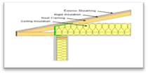
Attic ventilation is the traditional way of controlling temperature and moisture in an attic. In an unvented attic assembly, insulation is applied directly at the roofline of the building, either above or below the structural roof rafter. The roof ‘system becomes part of the insulated building enclosure. For this case, the thermal boundary of the building results in an unvented attic space between the ceiling gypsum board (gypboard) and the insulated roof above (Figure 3-35).
Figure 3-35: Unvented Attic Assembly With Insulation at the Ceiling and Between the Roof Rafters
Source: California Energy Commission
In ‘addition to meeting the mandatory minimum insulation requirements, the provisions of CBC, Title 24, Part 2.5, Section R806.5 must be met.
Check with the local building jurisdiction to determine its specific requirements for unvented attic conditions.
Combining this strategy with the additional design improvement of low air leakage for the rest of the building would achieve energy savings and compliance energy credit.
Furthermore, this design eliminates the need to seal or limit penetrations at the ceiling level, such as recessed cans, because the air and thermal boundary is now located at the roof deck.
Below-Deck Netted Insulation in Unvented Attics
Alternative types of insulation can provide high R-value insulation below the roof deck in an unvented attic. One approach is a boxed netted system that is suspended from the top member of the truss, or top chord, to provide a fill depth that completely encloses the top chord, creating a uniform insulation layer of loose-fill fiberglass across the entire underside of the roof deck. This method can be done with common loose-fill insulation tools and equipment. See Figure 3-36 for details of this type of below-deck netted insulation. Draped netted insulation, another approach to below-deck insulation, results in a nonuniform insulation layer, created by leaving the truss chords exposed and leading to increased thermal bridging (Figure 3-37).
Figure 3-36: Box Netted Insulation
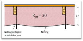
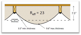
Figure 3-37: Draped Netted Insulation
Source: Owens Corning
Gable Ends in Unvented Attics
In unvented attics, where insulation is applied directly to the underside of the roof deck, framing for gable ends that separate the unvented attic from the exterior or unconditioned space shall be insulated to meet or exceed the wall R-value of the adjacent exterior wall construction. The backside of air-permeable insulation exposed to the unconditioned attic space shall be completely covered with a continuous air barrier.
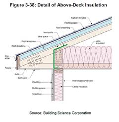
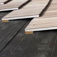
Requires insulation above the roof rafters, directly in contact with the roof deck to add value to the thermal integrity of the roof ‘system. Above-rafter insulation can be implemented with either asphalt shingles or clay/concrete tiles. The R-values for insulation installed above the roof rafters are lower than the R-values for insulation installed below the roof deck due to the added benefit of reduced thermal bridging when continuous insulation is applied to the roof deck. Further, when an air space is present between the roofing and the roof deck, the effect of insulation is greater than when there is no air space.
|
|
Check manufacturer’s specifications for proper nail schedules (fastening patterns); this will change depending on the roof pitch, truss spacing, and roofing material. |
Figure 3-39: Battens (Purlins) Installed With Above-Deck Insulation
Source: Building Science Corporation
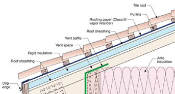
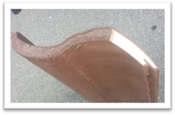
With concrete and clay tiles. Standard construction practice in California for concrete and clay tiles is to have an air gap between the tiles and roof deck due to the shape of the tiles and the way tiles are installed over battens. When adding insulation above the roof deck, there are two options to addressing the air gap. If the air gap is desired, one option is to install rigid insulation over the roof deck and a second roof sheating layer added above the rigid insulation. A vapor retarder would be above the second sheathing layer to host the purlins with the tiles installed over them (Figure 3-39). If the air gap is not desired, there may be insulation products available that can fit directly under concrete/clay or steel tile.
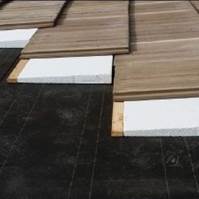
With asphalt shingles. When installing asphalt shingles with roof deck insulation, it is best to implement a ventilation method between the roofing product and the top sheathing or insulation, as shown in Figure 3-40, to prevent the roofing material from experiencing high temperatures and reducing effective product life.
Figure 3-40: Above-Deck Insulation and Spacers Installed With and Without Top Sheathing
![]()
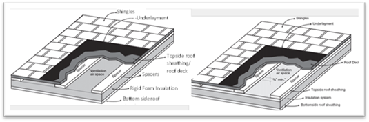
Source: ARMA technical bulletin No. 211-RR-94
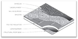
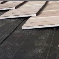
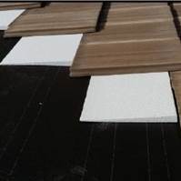
Spacers can be inserted either above or below a second roof sheathing to provide roof deck ventilation and a nailable base for asphalt shingles (Figure 3-41). Manufacturers offer prefabricated insulation products with spacers and top sheathing. Check manufacturers’ and trade association websites for a list of products available that provide an air space and nailable base.
Figure 3-41: Asphalt Shingles and Spacers Installed With Above-Deck Insulation
Source: PIMA Tech Bulletin #106
Example 3-28: Two Layers of Rigid Foam Board Above-Deck
Question: Can two layers of R4 rigid foam board be installed as an equivalent performance to R8 rigid foam insulation above the roof deck? If so, are there best practices for installing the two layers of insulation?
Answer: Yes, installing two R4 rigid foam board layers is equivalent in performance to R8. To prevent water infiltration, it is best to stagger the horizontal and vertical joints of the two layers and take care to seal each joint properly.
Example 3-29: Roof Material Directly Over Rigid insulation
Question: A project plans to install R6 rigid foam insulation above the roof deck with roofing material placed directly over the insulation. What are the best practices for installing the insulation?
Answer: Insulation can be installed directly on the roof deck with no air gap, but performance is improved if an air gap is installed between the rigid insulation and the roof deck. Using spacers or battens (purlins) are two strategies to create this air gap. Products exist that combine insulation, spacers, and additional sheathing for nailing asphalt shingles. Check with insulation manufacturers for available products.
Example 3-30: Fire Ratings Required by CBC, Chapter 15
Question: Does a roof assembly using above deck insulation meet Class A/B/C fire rating specifications, as determined by California Building Code (CBC), Chapter 15?
Answer: Application of above-deck insulation affects the fire rating classification of roof covering products. Roof covering products are rated to Class A/B/C based on the ASTM E108 (NFPA 256, UL790) test. Class A/B/C ratings are done with specific roof assemblies, and ratings are valid only when the installation is the same as the assembly as rated. Under current building code requirement, tile roof products installed directly over the roof deck or over purlins are automatically rated Class A. Chapter 15 in the California Building Code (and International Building Code Section 1505 for Fire Classification) specify that certain roofing materials are Class A without having to test to ASTEM E108. These materials include slate, clay, concrete roof tile, an exposed concrete roof deck, and ferrous and copper shingles; however, asphalt shingles are not covered under this category.
Insulation products, on the other hand, are subject to a different fire test from roof-covering products. The California Building Code and International Building Code (Section 2603 for Foam Plastic Insulation) require foam plastic insulation to be tested to demonstrate a flame-spread index of not more than 75 and a smoke-developed index of not more than 450 according to ASTM E84 (UL723). The requirements apply to roof insulation products, including XPS/polyiso/polyurethane above‐deck insulation and SPF below‐deck insulation products.
To ensure that roof assemblies with insulation meet the proper fire rating classification, roof product manufacturers and insulation manufacturers must test and develop assemblies that meet the CBC testing specifications.
Figure 3-42: Insulated Concrete Tile
Source: Green Hybrid Roofing
Insulated roof tile (IRT) is an option for improving the thermal performance of the roof assembly and lowering attic temperatures. IRT combines concrete or clay tiles with insulation as a packaged product (Figure 3-42). Most of the increase in R-value is due to the integration of insulation into the roofing product itself. Additional thermal performance can be gained by combining IRT with rigid foam insulation inserts (Figure 3-43). These tiles are lighter than typical roof tiles and have better thermal performance than traditional tiles due to the insulating core.
IRT can reduce radiant losses and maintain warmer roof deck temperatures, thereby reducing the potential for condensation. Using one of the options below provides additional R-value when conventional ceiling insulation is installed.
All four configurations (A-D) in Figure 3-43 can be installed without any significant changes to conventional roof or attic design (such as changes to fascia dimensions). IRT can be used in vented and unvented attic configurations.
Some IRT products are ASTM-rated for Class A fire rating (ASTM E108) and have CRRC certification for cool roof tiles in multiple colors. Depending on the configuration selected from the four options (A-D) in Figure 3-43, a U-factor between 0.18 and 0.10 can be achieved, with Option D performing the best. It is best practice to check with manufacturers about the ratings and certifications for each tile. Product manufacturers cite several advantages of the product due to the lightweight construction and increased insulation properties – ease of installation, ability to install similar to traditional roof tiles but at a much faster pace, less weight on the roof structure, increased thermal resistance, and improved thermal performance.
Figure 3-43: Insulated Roof Tile (IRT) (A) Attached Directly to Roof Deck, (B) Attached to Batten, (C) Attached Directly to Roof Deck With Wedged Foam Filling Air Space, and (D) Attached to Battens With Wedged Foam Filling Air Space
(A) (B)
(C) (D)
Source: Green Hybrid Roofing
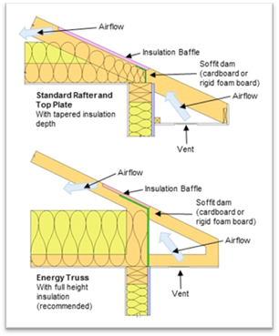
The use of an energy truss, usually referred to as a raised heel or extension truss, allows full depth, uncompressed insulation at the ceiling to continue to the ceiling edge where the roof and ceiling meet. For this strategy, the roof truss is assembled with an additional vertical wood framed section at the point where the top and bottom truss chords meet. The vertical section raises the top chord and provides increased space that can be filled with insulation. See Figure 3-44 for details of a raised heel truss. Benefits of this strategy include:
•Realizing the full benefit of ceiling insulation.
• Providing more space for air handler and duct systems if located in the attic.
The 2019 CBECC-Res compliance software allows for the modeling of raised heel trusses and provides credit for the additional insulation at the edges.
|
|
Other construction methods to achieve a similar outcome include framing with a rafter on raised top plate or using spray foam or rigid foam at the edge. |
Figure 3-44: Standard Truss vs. Raised Heel Energy Truss
Source: California Energy Commission
Figure 3-45: Nail Base Insulation Panel With Radiant Barrier Affixed to Trusses in a Vented Attic Configuration
The nail base insulation panel is an above-roof rafter insulation strategy that consists of exterior-facing OSB or other structural sheathing laminated to continuous rigid insulation, which is fastened directly to roof framing (Figure 3-45). This saves the time and expense of installing a structural sheathing layer above and below the rigid insulation. The nail base insulation panel creates a nailing surface for attaching roof cladding.
Suitable for vented and unvented attic assemblies, the exposed underside of the rigid insulation has a facer that provides a radiant barrier, as well as ignition/thermal barrier protection as required by code.
Example 3-31: Area-Weighted Averaging Insulation Levels
Question: A computer method analysis shows that a new house requires R-19 ceiling insulation to comply using the performance approach, but the minimum mandatory insulation level for ceiling insulation is R-22. Which insulation level should be used?
Answer: The mandatory minimum insulation requirement is an area-weighted average U-factor. Therefore, some areas can have lower insulation, such as R-19, but other areas will need to have higher levels of insulation so that the area-weighted average U-factor is at least 0.043.
Example 3-32: Minimum Insulation Levels When Using Performance Approach
Question: A small addition to an existing house appears to comply using only R-15 ceiling insulation with the performance approach. Does this insulation level comply with the standards?
Answer: No. R-15 would not be sufficient because the required minimum ceiling insulation level established by the mandatory measures is R-22. However, R-15 could be used in limited areas, as follows:
a. Attic roofs must have a weighted average U-factor of 0043 or less for the entire ceiling/roof.
b. Rafter roofs must have a weighted average U-factor of 0.054 or less for the entire ceiling/roof.
Advanced wall systems (AWS), also known as optimum value engineering (OVE) or advanced framing, refer to a set of framing techniques and practices that minimize the amount of wood and labor necessary to build a structurally sound, safe, durable, and energy-efficient building. AWS improves energy and resource efficiency while reducing first costs.
Reducing the amount of wood in wood-framed exterior walls improves energy efficiency through a reduced framing factor, allowing more insulation to be installed, and has greater resource efficiency for the
Figure 3-46: Wood-Framed Wall, 2x6 @ 24” oc, AWF With Three-Stud corners
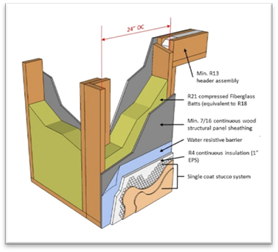
Source: California Energy Commission
materials being used. In ‘addition, using fewer framing studs reduces the effects of “thermal bridging” and increases the amount of insulation in the wall, resulting in a more energy-efficient building envelope. The framing factor assumed for calculating the energy performance of a wood-framed 2x4 wall at 16” on center is 25 percent. When AWS is used, the framing factor is reduced to 17 percent, reflecting the improved energy performance of the advanced wall ‘system.
Calculating Assembly U-Factors. Figure 3-46 depicts one AWS that achieves a U-factor of 0.048 with an exterior insulation of R-4, due to 24” stud spacing and R-13 header assemblies. Table 3-14 lists the assembly components for the AWS in Figure 3-46. These values were calculated using the parallel heat flow calculation method, documented in the 2009 ASHRAE Handbook of Fundamentals and outlined in Joint Appendices JA4.1.2 and JA4.6.
The construction assembly in Table 4.6.1 in JA4.6 assumes an exterior air film of R-0.17, a 3/8-inch layer of stucco of R-0.08 (SC01), building paper of R-0.06 (BP01), sheathing, or continuous insulation layer, if present, the cavity insulation/framing layer, 1/2-inch gypsum board of R-0.45 (GP01), and an interior air film 0.68. The framing factor is assumed to be 25 percent for 16-inch stud spacing, 22 percent for 24-inch spacing, and 17 percent for advanced wall system (AWS). Actual cavity depth is 3.5 inches for 2x4, 5.5 inches for 2x6.
|
Layer |
Assembly Type: Wall 2x6 @ 24” oc AWS |
R-Value | ||
|
Framing Material: Wood | ||||
|
Assembly Components |
Cavity (Rc) |
Frame (Rf) |
Header (Rh) | |
|
0 |
Frame Factor |
78% |
17% |
5% |
|
1 |
Outside Air Film |
0.17 |
0.17 |
0.17 |
|
2 |
Building Paper |
0.06 |
0.06 |
0.06 |
|
3 |
3/8-Inch Single Coat Stucco |
0.08 |
0.08 |
0.08 |
|
4 |
R4 Continuous Insulation (1” EPS) |
4 |
4 |
4 |
|
5 |
7/16-Inch Continuous Oriented Strand Board Sheathing (OSB) |
0.44 |
0.44 |
0.44 |
|
6 |
R-20 Fiberglass Batts |
20.0 |
-- |
-- |
|
7 |
Header Assembly – 2x Wood |
|
|
1.485 |
|
8 |
Header Assembly – 2.5 Inches of R4 Foam |
|
|
10 |
|
9 |
Header Assembly – 2x Wood |
|
|
1.485 |
|
10 |
2x6 Framing @ R-0.99/Inch |
-- |
5.445 |
-- |
|
11 |
½-Inch Gypboard |
0.45 |
0.45 |
0.45 |
|
12 |
Inside Air Film |
0.68 |
0.68 |
0.68 |
|
|
Subtotal R-Values |
25.88 |
11.325 |
18.85 |
|
|
U-Factors (Frame % x 1/R) |
0.0301 |
0.0150 |
0.0027 |
|
|
Assembly U-Factor (UCavity + UFrame + UHeader) |
Assembly |
0.048 | |
|
|
While AWS represents a range of practices, it must be adequately inspected to ensure framing contractors have adhered to all best practice construction techniques throughout the exterior envelope. Examples of construction practices for AWS that can be used as a general guide for building inspectors: |
|
1. Use a minimum 2x6 at 24” on-center wall framing. 2. Use precise engineering of headers on load-bearing walls. 3. Install 2x4, 2x6, or I-joist headers on exterior non-load-bearing walls. 4. Eliminate cripple studs at window and door openings less than 4 feet wide. 5. Align window/door openings with standard stud spacing. 6. The king stud, on at least one side of the window/door opening, must take the place of an on-layout AWS stud. 7. Use an insulated corner, either a two-stud corner or a California (three-stud) corners, as in the examples provided in Figure 3-47. 8. Nailing for interior gypsum board can be accomplished with drywall clips, 1x nailer strip, recycled plastic nailing strip. Drywall clips reduce the potential for drywall cracking. 9. Use ladder block where interior partitions intersect exterior walls, instead of three-stud channels. 10. Eliminate unnecessary double-floor joists underneath nonbearing walls. 11. Use metal let-in T-bracing or other methods on nonshear walls to allow full insulation. 12. Include detailed framing plans and elevations on the construction permit plan set. 13. Optimize house design for efficient material use (for example, reducing header spans, designing exterior surfaces in 2-foot modules, designing clear spans to eliminate interior bearing walls). 14. Build with “insulated headers.” An example of a single-ply insulated header is provided in Figure 3-48. See Reference Appendices RA3.5 for more information. 15. Use engineered lumber. Examples include “I”-joists, open web floor trusses, 2x raised heel roof trusses, glulam beams, laminated veneer lumber (LVL), laminated strand lumber (LSL), parallel strand lumber (PSL), oriented strand board (OSB). 16. Eliminate trimmers at window and door opening headers less than 4 feet wide, only when rated hangers are used and noted on the plans. 17. Use 2x4 or 2x3 interior nonload-bearing walls. 18. Integrate framing design with HVAC system. 19. Use “inset” shear wall panels. | |
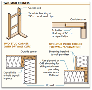
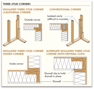
Figure 3-47: Advanced Framing Corners
Source: APA Advanced Framing Guide
Figure 3-48: Headers Designs With Cavity Insulation Space
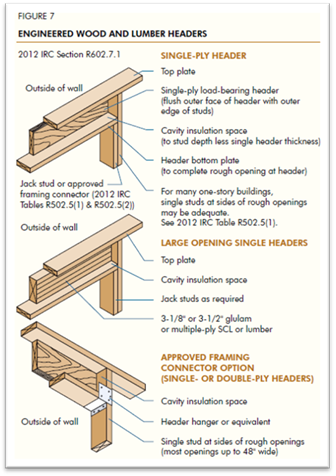
Source: APA Advanced Framing Guide
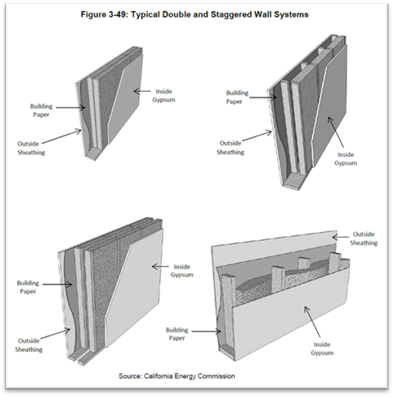
Double and Staggered Wall Assemblies. Double-wall and staggered-wall systems were developed to better accommodate electrical and plumbing systems, allow higher levels of insulation, and provide greater sound reduction. The advantages of these types of wall systems are the following:
1. Smaller dimensional lumber can be used.
2. It is easier to install insulation properly.
3. It eliminates thermal bridging through the framing.
4. It reduces sound transmission through the wall.
With double walls, insulation may be on one side of the wall or on both (higher R-values). It is not uncommon to find double walls with insulation installed within the outside wall cavities, leaving the inside wall sections open for wiring and plumbing (Figure 3-49).
With staggered walls, thermal batt insulation may be installed horizontally or vertically, butting the sides of the insulation until the cavity across the entire wall section is completely filled.
A change from wood framing to metal framing can significantly affect compliance. Metal-framed assemblies are often chosen where greater structural integrity is necessary or in climate conditions where greater durability is necessary to protect from the effects of excessive moisture exposure. Metal-framed wall construction generally requires a continuous layer of rigid insulation to meet the mandatory minimum wall insulation levels and the prescriptive requirements since metal is more conductive than wood. In JA4, Table 4.2.4 and Table 4.2.5 have U-factors for metal-framed ceiling/roof constructions. Table 4.3.4 has U-factors for metal-framed walls. Table 4.4.4 and Table 4.4.5 have U-factors for metal-framed floors.
To comply prescriptively, a non-wood-framed assembly, such as a metal-framed assembly, must have an assembly U-factor that is equal to or less than the U-factor of the wood-framed assembly for that climate zone.
The high performance structural foam wall assembly is an advanced assembly ‘system that consists of closed cell spray foam (ccSPF) placed in the cavity bonded to wood framing and continuous rigid board insulation on the exterior of the frame. The bond that occurs between the ccSPF, the framing, and the continuous rigid insulation can provide code-compliant wind and seismic structural load resistance without the use of OSB sheathing (Figure 3-50).
Figure 3-50: Example Structural Foam Wall System
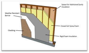
Source: California Energy Commission
A builder can configure the thicknesses of the cavity ccSPF, rigid insulation, and alternative cavity insulation to attain U-factors of 0.050 or better in 2x4 at 24” on center assembly. The structural foam wall assembly can be combined with advanced framing or OVE techniques to increase energy and resource efficiency while reducing material and labor costs.
|
|
Structural foam wall systems use ccSPF to insulate, air seal, and structurally bond exterior foam sheathing with wall framing to allow builders to construct 2x4 at 24” on center, while improving structural and thermal performance. |
An energy credit can be taken in compliance software for controlled ventilation crawl spaces (CVC). This credit requires insulating the foundation stem wall, using automatically controlled crawl space vents, and covering the entire ground soil area with vapor retarder for moisture control on the crawl space floor.
|
|
Raised Floor Insulation Requirem386ents |
|
Buildings that have crawl space foundations must meet mandatory requirements for insulation of a raised floor separating the unconditioned crawl space from conditioned space above (§150.0[d]). There also are prescriptive requirements for insulating raised floors in §150.1(c)1C. | |
An alternative to underfloor insulation is insulating the stem wall of the foundation crawl space. Insulating the crawl space foundation can improve the thermal efficiency of the floor ‘system by:
1. Reducing heat transfer into the unconditioned crawl space.
2. Reducing moisture buildup in the crawl space.
3. Minimizing insulation exposure to adverse weather prior to enclosing the building shell.
Eligibility Criteria. The following eligibility criteria in Residential Appendix RA4.5.1 are required to be met to use the CVC energy compliance credit:
1. Ventilation: All crawl space vents must have automatic vent dampers. Automatic vent dampers must be shown on the building plans and installed. Dampers shall be temperature actuated to be fully closed at about 40°F and fully open at about 70°F. Cross-ventilation consisting of the required vent area shall be distributed between opposing foundation walls.
2. Insulation: The R-value of insulation placed on the foundation stem wall shall be equal to or greater than the wall insulation above the raised floor. Stem wall insulation shall run vertically along the stem wall and horizontally across the crawl space floor for a distance of 2 feet (24 inches).
3. Direct Earth Contact: Foam plastic insulation used for crawl space insulation having direct earth contact shall be a closed–cell, water-resistant material and meet the slab edge insulation requirements for water absorption and water vapor transmission rate specified in the mandatory requirements (§110.8[g]1).
4. Vapor Retarder: A Class I or Class II vapor retarder rated as 1.0 perm or less must be placed over the earthen floor of the crawl space to reduce moisture entry and protect insulation from condensation in accordance with RA4.5.1. This requires essentially a polyethylene-type ground cover having a minimum 6 mil thickness (0.006 inch) or approved equal. The vapor retarder must be overlapped a minimum of 6 inches at joints and shall extend over the top of footings and piers. All overlapping of joints shall be sealed with tape, caulk, or mastic.
•Penetrations, tears, and holes in the vapor barrier shall be sealed with tape, caulk, or mastic.
•Edges of the vapor retarder shall be turned up a minimum of 4 inches at the stem wall and securely fastened and before insulation is installed.
•In sloping crawl space ground soil areas, the vapor retarder shall be securely held in place using fastening methods such as spiked with 5-inch gutter nails, then have proper sealing of penetration holes.
•The vapor retarder shall be shown on the plans.
Figure 3-51: Controlled Ventilation Crawl Space

Source: California Energy Commission
Site Drainage. Crawl space buildings in particular are susceptible to moisture ponding when good drainage and/or moisture removal designs are not employed. All building designs should ensure that proper site engineering and drainage away from the building is maintained. This includes landscaping techniques that emphasize sound water management strategies.
Ground Water and Soils. Local groundwater tables at maximum winter recharge elevation should be below the lowest excavated elevation of the site foundation. Sites that are well-drained and that do not have surface water problems are generally good candidates for this stem wall insulation strategy. However, allowance for this alternative insulating technique is entirely at the enforcement agency’s discretion. The building permit applicant should be prepared to provide supporting information that site drainage strategies (for example, perimeter drainage techniques) will prevent potential moisture concerns.
An energy credit is allowed for single-family buildings through the performance approach when the rate of envelope air leakage of the building is less than the air leakage rate assumed for the standard design building of 5 ACH50.
|
|
A third-party HERS Rater shall verify the air leakage rate shown on compliance documentation through diagnostic testing of the air leakage of the building. |
Figure 3-52: Blower Door Testing

Blower Door Testing. The blower door air leakage testing involves closing all the windows and doors; pressurizing the house with a special fan, usually positioned in a doorway (Figure 3-52); and measuring the leakage rate, measured in cubic feet per minute at a 50 Pa pressure difference (CFM50).
The measurement procedure is described in Residential Appendix RA3.8 and was derived from the Residential Energy Services Network's (RESNET) Mortgage Industry National Home Energy Rating Standards, Standard 800, which is based on ASTM E779 air-tightness measurement protocols. This procedure requires the use of software consistent with ASTM E779. This test method is intended to produce a measure of the airtightness of a building envelope for determining the energy credit allowance for reduced building air leakage.
|
|
Tips for Implementing the Reduced Building Air Leakage Compliance Credit |
|
1. This procedure shall be used only to verify the building air leakage rate before the building construction permit is finalized when an energy credit for reduced air leakage is being claimed on compliance documentation. 2. The HERS Rater shall measure the building air leakage rate to ensure measured air leakage is less than or equal to the building air leakage rate stated on the certificate of compliance and all other required compliance documentation. HERS-verified building air leakage shall be documented on compliance forms. 3. This is a whole-building credit; therefore, no credit is allowed for the installation of envelope measures that may help reduce the air leakage rate of the building, such as for an exterior air retarding wrap or for an air barrier material or assembly meeting the requirements described in Section 3.5.8 under Quality Insulation Installation (QII). | |


