|
|
MANDATORY |
PRESCRIPTIVE |
PERFORMANCE |
|
|
|
| |
|
Insulation |
§110.8(a) - (d), §110.8(g) - (h), §150.0(a) - (d), §150.0(f) |
Table 150.1-A |
The Energy Standards encourage the use of energy-saving techniques and designs for showing compliance. Insulation is one of the least expensive measures to improve building energy efficiency. Insulation requires no maintenance, helps improve indoor comfort, and provides excellent sound control. Adding extra insulation later is more expensive than maximizing insulation levels at the beginning of construction. Innovative construction techniques and building products are being used more often by designers and builders who recognize the value of energy-efficient, high-performance buildings.
When the performance compliance method is used, an energy credit can be taken for design strategies that reduce building energy use below the standard design energy budget (compliance credit). Some strategies may require third-party verification by a HERS Rater; others do not. For more on the performance method, see Section 3.6 and Chapter 8.
Table 3-8: Relevant Sections in the Energy Standards
|
|
MANDATORY |
PRESCRIPTIVE |
PERFORMANCE |
|
|
|
| |
|
Insulation |
§110.8(a) - (d), §110.8(g) - (h), §150.0(a) - (d), §150.0(f) |
Table 150.1-A |
There are four basic types of insulation or “insulation systems" installed in residential buildings: batt and blanket, loose-fill, spray polyurethane foam (SPF), and rigid insulation. The use varies based on the design and type of construction.
3.5.1.1 Batt and Blanket
Batt and blanket insulation is made of mineral fiber and mineral wool (processed fiberglass, rock, slag wool); animal wool or cotton-based products; or cellulose materials. These products are used to insulate below floors, above ceilings, below roofs, and within walls. They offer ease of installation with R-values set by the manufacturer based on size and thickness. They are available with facings, some serve as vapor retarders, and have flanges to aid in installation to framed assemblies. Many are available as unfaced material and can be easily friction-fitted into framed cavities.
Batt and blanket insulation allows easy inspection, and installation errors can readily be identified and remedied, including breeches in the air barrier system that allow air leakage.
|
|
Care should always be taken to install insulation properly, filling the entire cavity and butting ends or sides of the batt material to ensure uniformity of installation. Batt and blanket insulation material must be delaminated or cut to allow for wiring, plumbing, and other penetrations within the cavity. See Section 3.5. |
3.5.1.2 Loose-Fill Insulation
Figure 3-15: Cellulose-Insulated Wall

Loose-fill is insulation that has a pneumatic or blown installation process, including cellulose, fiberglass, mineral wool and natural wool (animal or cotton-based products). Blown wall insulation can be an effective way to deal with the irregularities of wall cavities, especially the spaces around pipes, electric cables, junction boxes, and other equipment embedded in wall cavities (see Figure 3-15). The R-value of blown wall insulation material installed in closed cavities is determined by the installed thickness and density. This differs from manufactured products such as fiberglass or mineral wool batts for which the R-value has been tested and arrives at the construction site in preformed lengths and thicknesses with set R-value thicknesses.
When installed in floors, walls, and other assemblies, these fibrous insulations are held in place in one of three ways:
1. Preinstalled netting or fabric
2. Use of existing cavity walls
3. Use of integral adhesives
|
|
Blown wall insulation must be thoroughly checked to ensure the R-value is achieved. R-value depends on the installed density of the material at the building site, and the building official should ensure that the installed density meets manufacturer specifications. See Section 3.5. |
In closed cavities:
•A line of sight down a wall section can hide imperfections in the installation, leading to underachieving stated R-values.
•Depressions and voids within the insulated cavity are areas lacking in R-value performance.
•Where netting is used, overspraying can result in a higher installed density (higher R-value) but can be troublesome for attaching gypsum board to wall framing.
•Where cavities have been underfilled, there may be voids or “soft” areas under the netting. These areas must be corrected by adding insulation, or the area must be removed, and new material must be blown into the cavity.
In open cavities (attic floor or open wall):
Figure 3-16: Attic Floor

Source: California Energy Commission
•No netting or preexisting wall cladding is needed (Figure 3-16).
•In open horizontal applications, such as attic floors, no adhesives are used, and the R-value is verified by thickness and rated coverage.In open vertical applications, integral adhesives are used to hold the fibers in place. Water-activated adhesives are used for moist-spray cellulose, and water or polymer adhesives are used for fiberglass loose-fill applications. The fiber and/or adhesive formulation cause the insulation to adhere to itself and stick to surfaces of the wall cavity.
•Excess insulation that extends past the wall cavity is scraped off and recycled.
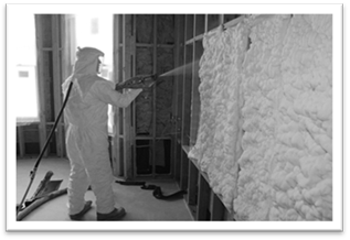
3.5.1.3 Spray Polyurethane Foam (SPF)
SPF is a two-part, liquid-foamed thermoset plastic (such as polyurethane). Polyurethane is formed by the reaction of an isocyanate and a polyol. Blowing agents, catalysts, and surfactants are added to develop a cellular structure before the polyurethane mixture cures. At application, the SPF material forms in place to provide insulation, an air seal, and, in closed-cell SPF, an integral vapor retarder and water barrier.
SPF insulation is a two-component reactive system mixed at a spray gun or a single-component system that cures by exposure to humidity. The liquid is sprayed through a nozzle into the wall, roof, ceiling, and floor cavities. SPF insulation can be formulated to have specific physical properties, such as density, compressive strength, fire resistance, and R-value.
SPF insulation is spray-applied to adhere fully to the substrate and other framing faces to form a complete air seal within the construction cavities.
|
|
SPF must be separated from the interior of the building, including attic spaces, by an approved thermal barrier complying with Section 316.4 of the CRC. |
There are two common types of SPF insulation:
Figure 3-17: Open-Cell SPF Installed in Wall Cavity
Source: SPFA
A. Low-Density Open-Cell SPF (ocSPF) Insulation: A spray-applied polyurethane foam insulation having an open cellular structure resulting in an installed nominal density of 0.4 to 1.5 pounds per cubic foot (pcf), ocSPF has been assigned a default R-value of 3.6 per inch for compliance, but some products can achieve higher R-values. The ocSPF insulation is sprayed then expands to fill the framed cavity (Figure 3-17). Excess insulation may be trimmed by a special tool to simplify interior cladding installation. The average thickness of the foam insulation must meet or exceed the required R-value. Depressions in the foam insulation surface shall not be greater than ½-inch of the required thickness, provided these depressions do not exceed 10 percent of the surface area being insulated. Note: If using the default R-value of 3.6 per inch, the entire wall cavity must be filled to achieve the mandatory minimum wall insulation requirements for 2x4 and 2x6 framing.
Figure 3-18: Closed-Cell SPF Installation in a Wall Cavity

Source: SPFA
C. Medium-Density Closed-Cell SPF (ccSPF) Insulation: A spray-applied polyurethane foam insulation having a closed cellular structure resulting in an installed nominal density of greater than 1.5 to less than 2.5 pounds per cubic foot (pcf), CcSPF has been assigned a default R-value of 5.8 per inch for compliance, but some products can achieve higher R-values. The average thickness of the foam insulation must meet or exceed the required R-value. Depressions in the surface of the foam insulation shall not be greater than ½-inch of the required thickness at any given point of the surface area being insulated. CcSPF is not required to fill the cavity (Figure 3-18).
|
|
SPF R-value depends on the installed thickness, and the building official should ensure the thickness and uniformity of the SPF material within each cavity of framed assemblies meets manufacturer specifications. |
|
Thickness of SPF Insulation |
R11 |
R13 |
R15 |
R19 |
R20 |
R21 |
R22 |
R25 |
R30 |
R38 |
|
Required Thickness of ccSPF Insulation (inches) |
2.00 |
2.25 |
2.75 |
3.25 |
3.50 |
3.75 |
4.00 |
4.50 |
5.25 |
6.75 |
|
Required Thickness of ocSPF Insulation (inches) |
3.00 |
3.50 |
4.20 |
5.30 |
5.50 |
5.80 |
6.10 |
6.90 |
8.30 |
10.6 |
Equation 3-2: Alternative Calculation for Total R-Value:
Thickness of insulation
"Tested R-value per inch" as listed in the Table of R-values or R-value Chart from the manufacturer's current ICC Evaluation Service Report (ESR) that shows compliance with Acceptance Criteria for Spray-Applied Foam Plastic Insulation--AC377
Overall assembly U-factors are determined by selecting the assembly type, framing configuration, and cavity insulation rating from the appropriate JA4 table, other approved method specified in JA4, or using the Energy Commission-approved compliance simulation software.
3.5.1.4 Rigid Insulation
Figure 3-19: Properly Installed Rigid Insulation With Sealant Tape

Source: U.S. Environmental Protection Agency
Rigid board insulation sheathing is made from fiberglass, mineral wool, expanded polystyrene (EPS), extruded polystyrene (XPS), polyisocyanurate (ISO), or polyurethane (PUR). It varies in thickness, and some products can provide up to R-6 per inch of thickness.
This type of insulation is used for above-roof decks, exterior walls, cathedral ceilings, basement walls; as perimeter insulation at concrete slab edges; and to insulate special framing situations such as window and door headers and around metal seismic bracing. Rigid board insulation may also be integral to exterior siding materials. Properly sealed rigid insulation can be used continuously across an envelope surface to reduce air infiltration and exfiltration, and thermal bridging at framing.
|
|
Proper installation of continuous rigid insulation may include button cap nails, furring strips, flashing, sealant tape, and design of the drainage plane. See Figure 3-19. |
The 2019 California Building Code (CBC) provides guidance on fastener penetration depth, diameter, and spacing for exterior foam sheathing in Section R703.11.2. CRC Table 703.15.1, reproduced below in Figure 3-20, shows the fastener spacing for cladding attachment over foam sheathing to wood framing.
Figure 3-20: Fastening Requirements Over Foam Sheathing
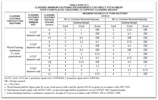
Source: 2019  California Building
Code
California Building
Code
Manufacturers must certify that insulating materials comply with the California Quality Standards for Insulating Materials (CCR, Title 24, Part 12, Chapters 12-13), which ensure that insulation sold or installed in California performs according to stated R-values and meets minimum quality, health, and safety standards.
|
|
Builders and enforcement agencies shall use the California Department of Consumer Affairs Directory of Certified Insulation Material to verify the certification of the insulating material. If an insulating product is not listed in the current edition of the directory, contact the Department of Consumer Affairs, Bureau of Electronic and Appliance Repair, Home Furnishings and Thermal Insulation, at (916) 999-2041 or by email at bear.enf@dca.ca.gov. |
3.5.2.1 Urea Formaldehyde Foam Insulation §110.8(b)
The mandatory measures restrict the use of urea formaldehyde foam insulation. The restrictions are intended to limit human exposure to formaldehyde, a volatile and harmful organic chemical.
If foam insulation is used that has urea formaldehyde, it must be installed on the exterior side of the wall (not in the cavity of framed walls), and a continuous vapor retarder must be placed in the wall construction to isolate the insulation from the interior of the space. The vapor retarder must be 4-mil- thick (0.1 mm) polyethylene or equivalent.
3.5.2.2 Flame Spread Rating of Insulation §110.8(c)
The California Quality Standards for Insulating Materials requires that exposed facings on insulation material be fire resistant and tested and certified not to exceed a flame spread index of 25 and a smoke development index of 450. Insulation facings must be in contact with the finished assembly surface or they are considered exposed applications and cannot be installed. Flame spread indexes and smoke development indexes are shown on the insulation or packaging material or may be obtained from the manufacturer.
3.5.3.1 Loose Fill Insulation in the Attic §150.0(b)
Loose fill insulation must be blown in evenly, and insulation levels must be documented on the certificate of installation (CF2R). The insulation level can be verified by checking that the depth of insulation conforms to the manufacturer’s coverage chart for achieving the required R-value. The insulation also must meet the manufacturer’s specified minimum weight per ft² for the corresponding R-value.
|
|
When installing loose fill insulation, the following guidelines should be followed: 1. For wood trusses that provide a flat ceiling and a sloped roof, the slope of the roof should be 4:12 or greater to provide adequate access for installing the insulation. Insulation thickness near the edge of the attic will be reduced with all standard trusses, but this is acceptable as long as the average thickness is adequate to meet the minimum insulation requirement. 2. If the ceiling is sloped (for instance, with scissor trusses), loose fill insulation can be used as long as the slope of the ceiling is no more than 4:12. If the ceiling slope is greater than 4:12, loose fill should be used only if the insulation manufacturer will certify the installation for the slope of the ceiling. 3. At the apex of the truss, a clearance of at least 30 inches should be provided to simplify installation and inspection. |
3.5.3.2 Wet Insulation Systems §110.8(h)
Wet insulation systems are roofing systems where the insulation is installed above the waterproof membrane of the roof. Water can penetrate this insulation material and affect the energy performance of the roofing assembly in wet and cool climates. In Climate Zones 1 and 16, the insulating R-value of continuous insulation materials installed above the waterproof membrane of the roof must be multiplied by 0.8, and installers must use the result value in choosing the table column in Reference Joint Appendix JA4 for determining assembly U-factor (when using the Joint Appendix JA4 table to comply). See the footnotes for Tables 4.2.1 through 4.2.7 in the Reference Joint Appendix JA4.
3.5.3.3 Recessed Luminaires §150.0(k)1C
Luminaires recessed in insulated ceilings can create thermal bridging through the assembly. Not only does this degrade the performance of the ceiling assembly, but it can permit condensation on a cold surface of the luminaire if exposed to moist air, as in a bathroom. Refer to the Lighting Chapter 6 for more information regarding the applicable requirements for recessed luminaires.
|
|
Luminaires recessed in insulated ceilings must meet three requirements. |
|
Figure 3-21: IC-Rated Luminaire (Light Fixture)
1. They must be listed as defined in the Article 100 of the California Electric Code for zero clearance insulation contact (IC) by Underwriters Laboratories or other testing/rating laboratories recognized by the International Code Council (ICC). This enables insulation to be in direct contact with the luminaire. 2. The luminaire must have a label certified as per §150.0(k)1Cii for airtight (AT) construction. Airtight construction means that leakage through the luminaire will not exceed 2.0 cfm when exposed to a 75 Pa pressure difference, when tested in accordance with ASTM E283. 3. The luminaire must be sealed with a gasket or caulk between the housing and ceiling. Source: California Energy Commission | |
3.5.3.4 Mandatory Requirements
Wood-framed roof/ceiling construction assemblies must have at least R-22 insulation or a maximum U-factor of 0.043 based on 16-inch-on-center wood-framed rafter roofs, as determined from JA4. Some areas of the roof/ceiling can be greater than the maximum U-factor as long as other areas have a U-factor lower than the requirement and the weighted average U-factor for the overall ceiling/roof is 0.043 or less.
Metal-framed and roof/ceiling constructions other than wood-framed must have a U-factor of 0.043 or less to comply with the mandatory measure. If the insulation is not penetrated by framing, such as rigid insulation laid over a structural deck, then the rigid insulation can actually have a rated R-value of less than R-22 so long as the total roof/ceiling assembly U-factor is not greater than U-0.043.
3.5.3.5 Prescriptive Requirements §150.1(c) and Table 150.1-A
The 2019 Energy Standards are designed to offer flexibility to the builders and designers of residential new construction in terms of achieving the intended energy efficiency targets. As such, the Energy Standards offer several options for achieving one of two design objectives related to improving energy performance of homes built with ventilated attics in Climate Zones 4, 8-16, as shown in Figure 3-22.
Figure 3-22: Ventilated Attic Prescriptive Compliance Choices
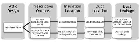
High Performance Ventilated Attic (HPVA). This approach reduces temperature differences between the attic space and the conditioned air being transported through ductwork in the attic. The package consists of insulation below the roof deck (Option B) in addition to insulation at the ceiling, R-8 ducts, and 5 percent total duct leakage of the nominal air handler airflow.
Ducts in Conditioned Space (DCS). Ducts and air handlers are within the thermal and air barrier envelope of the building.
|
|
The Ducts in Conditioned Space (Option C) requires field verification by a HERS Rater to meet the prescriptive requirement. |
All the prescriptive requirements for HPVA or DCS are based on the assumption that the home is built with the following construction practices:
A. The attic is ventilated with an appropriate free vent area as described below.
B. The roof is constructed with standard wood rafters and trusses.
C. For HPVA, the outermost layer of the roof construction is either tiles or a roofing product installed with an air gap between it and the roof deck.
D. The air handler and ducts are in the ventilated attic for HPVA and are in conditioned space for DCS.
E. The air barrier is located at the ceiling (excludes “cathedral” sealed attic roof/ceiling systems).
If a building design does not meet all of these specifications, it must comply through the performance approach.
Example 3-17: Cathedral Ceilings
Question: If 5 percent of a roof will be a cathedral ceiling, can it still comply under the prescriptive requirements?
Answer: No. The entire attic must be a ventilated space with the building air barrier located at the ceiling with standard wood rafter trusses to comply with the prescriptive requirements. This project must comply through the performance approach.
Example 3-18: Sealed (Unventilated) Attics
Question: Does a sealed (unventilated) attic with insulation at the roof deck comply under the prescriptive requirements?
Answer: No. The entire attic must be a ventilated space with the building air barrier located at the ceiling with standard wood rafter trusses to comply with the prescriptive requirements. This project must comply through the performance approach.
Example 3-19: Insulation Above the Roof Deck
Question: Does a ventilated attic with insulation above the roof deck comply under the prescriptive requirements?
Answer: No. The insulation must be located below the roof deck between the roof rafters to comply with the prescriptive requirements. If insulation is above the roof deck, the project must comply through the performance approach.
Example 3-20: Asphalt Shingles
Question: A home with asphalt shingle roofing, having no air gap, has a ventilated attic with insulation installed below the roof deck between the roof rafters (HPVA) and at the ceiling meeting prescriptive insulation levels. Does this home comply with the prescriptive requirements?
Answer: No. The roofing product must be of a type that is installed with an air gap between the product and the roof deck, such as concrete tile, to comply with the prescriptive requirements. If a roofing product with no air gap between the product and the roof deck is installed, the project must comply through the performance approach.
Example 3-21: Gable Ends in High Performance Ventilated Attics
Question: In addition to the roof underdeck, do gable end walls in high performance ventilated attics (HPVA) need to be insulated?
Answer: No. Gable end walls do not need to be insulated when designing and installing a HPVA.
Example 3-22: Attic Insulation Placement
Question: When installing roof/ceiling insulation, does the insulation need to be installed on the entire roof/ceiling, including areas over unconditioned space?
Answer: It depends. The insulation should be installed at the roof/ceiling in one of the following ways:
(1) If the attic is an open or undivided space, then the entire roof/ceiling should be insulated. This includes portions of the roof/ceiling over an unconditioned space such as a garage.
(2) If the attic has a continuous air barrier separating the attic over unconditioned space from the attic over conditioned space, then only the portions of the roof/ceiling over conditioned space should be insulated. It is recommended, but not required, that the air barrier also be insulated.
High Performance Ventilated Attics §150.1(c).1
This section describes the prescriptive requirements and approaches necessary for HPVA as they relate to roof/ceiling insulation. HVAC aspects of the HPVA including duct insulation and duct leakage are described in Chapter 4. Requirements and approaches to meet the ducts in conditioned space (DCS) are described in Chapter 4 of this ‘manual.
Section 150.1(c).1 requires different values of roof and ceiling insulation, depending on whether the HPVA (Option B) or DCS (Option C) is chosen. Figure 3-23 shows a prescriptive requirements checklist for each option based on Tables 150.1-A and 150.1-B.
 Figure 3-23: Prescriptive Insulation
Options
Figure 3-23: Prescriptive Insulation
Options
|
High Performance Ventilated Attics |
Ducts in Conditioned Space | |
|
Option B1 Single-Family |
Option B1 Multifamily |
Option C |
|
¨ Vented attic ¨ R-19 (CZ 4, 8-16) below roof deck batt, spray in cellulose/fiberglass secured with netting, or spray foam ¨ R-38 (CZ 1, 2, 4, 8-16) ceiling insulation or R-30 (CZ 3, 5-7) ¨ Radiant barrier (CZ 2, 3, 5-7) ¨ Air space between roofing and the roof deck ¨ R-6 or R-8 duct insulation (climate zone specific) ¨ 5% total duct leakage |
¨ Vented attic ¨ R-19 (CZ 4, 8-9, 11-15) or R-13 (CZ 10, 16) below roof deck batt, spray in cellulose/fiberglass secured with netting, or spray foam ¨ R-38 (CZ 1, 2, 4, 8-16) ceiling insulation or R-30 (CZ 3, 5-7) ¨ Radiant barrier (CZ 2, 3, 5-7) ¨ Air space between roofing and the roof deck ¨ R-6 or R-8 duct insulation (climate zone specific) ¨ 5% total duct leakage |
¨ Vented attic ¨ R-38 (CZ 1, 11-16) ceiling insulation or R-30 (CZ 2-10) ¨ R-6 or R-8 ducts (climate zone-specific) ¨ Radiant barrier (CZ 2-15) ¨ HERS-verified ducts in conditioned space |
|
Table 150.1-A Assembly Option B |
Table 150.1-B Assembly Option B |
Assembly Option C |
|
1 Option B is the Standard Design used to set the energy budget for the Performance Approach. | ||
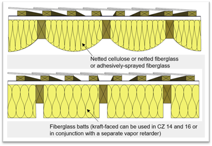
Below Roof Deck Insulation Option B. In a vented attic, air-permeable or air-impermeable insulation (batt, spray foam, loose-fill cellulose, or fiberglass) should be placed directly below the roof deck between the truss members and secured in place to provide a thermal break for the attic space. Insulation must be in direct contact with the roof deck and secured by the insulation adhesion, facing, mechanical fasteners, wire systems, a membrane material, or netting. Batts supported with cabling or other mechanical methods from below shall have supports that are less than or equal to 16” apart and no farther than 8” from the end of the batt.
When batt thickness exceeds the depth of the roof framing members, full-width batts must be used to fit snugly and allow batts to expand beyond the framing members. Full coverage of the top chord framing members by insulation is recommended as best practice but is not required.
Figure 3--24: Details of Option B Assembly
Source: California Energy Commission
Figure 3-25: Placement of Insulation Below the Roof Deck
Source: California Energy Commission
|
|
When insulation is installed below the roof deck to meet the prescriptive requirements of Option B, a radiant barrier is not required. However, a draped radiant barrier may be installed to receive performance credit. |
Vapor Retarders (Option B). Attic vapor retarders are not required by the Energy Standards in most climates when using spray foam, blown-in insulation, or unfaced batts, and when sufficient attic ventilation is maintained. Although not required, the use of vapor retarders can provide additional security against possible moisture buildup in attic and framed assemblies. In Climate Zones 14 and 16, a Class I or Class II vapor retarder must be used to manage moisture as stated in CBC, Title 24, Part 2.5, Section R806.2.
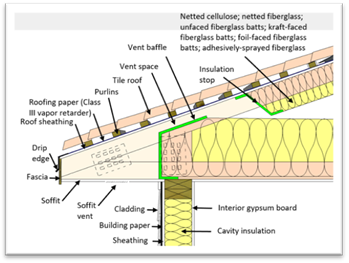
Attic Ventilation (Options B and C)
Figure 3-26: Insulation Air Baffles
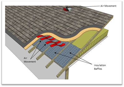
Source: Building Science Corporation
Proper attic ventilation occurs at two points at the roof: the soffit (or eave) vents and the ridge (or eyebrow) vents. Ridge or eyebrow venting must be maintained, as shown in Figure 3-26.
When installing insulation below the roof deck, vent baffles and insulation barriers should be used to maintain proper ventilation space. Proper airflow through the space helps remove moisture and prevents any associated issues.
Figure 3-27: Baffles at the Eave in Attics

Source: California Energy Commission
Where ceiling insulation is installed next to eave or soffit vents, a rigid baffle should be installed at the top plate to direct ventilation air up and over the ceiling insulation. (See Figure 3-27.) The baffle should extend beyond the height of the ceiling insulation and should have sufficient clearance between the baffle and roof deck at the top. There are several acceptable methods for maintaining ventilation air, including preformed baffles made of either cardboard or plastic. In some cases, plywood or rigid foam baffles are used.
The California Building Code (CBC) requires a minimum vent area to be provided in roofs with attics, including enclosed rafter roofs creating cathedral or vaulted ceilings. Check with the local building jurisdiction to determine which of the two CBC ventilation requirements are to be followed:
1. CBC, Title 24, Part 2, Vol. 1, Section 1203.2 requires that the net-free ventilating area shall not be less than 1/300 of the area of the space ventilated.
2. CBC, Title 24, Part 2.5, Section R806.2 requires that the net-free ventilating area shall not be less than 1/150 of the area of the space ventilated. This ratio may be reduced to 1/300 if a ceiling vapor retarder is installed in Climate Zones 14 and 16.
If meeting Option 1 above, a minimum of 40 percent and not more than 50 percent of the vents must be located in the upper portion of the space being ventilated at least 3 feet above the eave or cornice vents.
Insulation shall not block the free flow of air, and a minimum 1-inch air space shall be provided between the insulation and the roof sheathing and at the location of the vent.
Ventilated openings are covered with corrosion-resistant wire cloth screening or similar mesh material. When part of the vent area is blocked by meshes or louvers, the resulting “net-free area” of the vent must be considered to determine if ventilation requirements are met.
Many jurisdictions in California are covered by Wildland Urban Interface (WUI) regulations where specific measures for construction materials must be used to improve fire resistance for the building. These regulations require special vents that are expressly tested to resist the intrusion of flame and burning embers. Check with the building department to ensure compliance with local codes.
Example 3-23: Installation Doesn’t Match Compliant Design Option
Question: A new construction project in Climate Zone 12 with HVAC ducts in the attic was designed to meet the prescriptive requirements for below roof deck and ceiling insulation. Due to miscommunication amongst the team, the roof deck insulation was not installed, and R-49 ceiling insulation was installed instead. Does this project still comply?
Answer: This project no longer meets the prescriptive requirements and must follow the performance approach. For future projects, clearly communicating the project expectations to all team members early in the construction process is the key to succeeding at this design strategy. Having a project initiation meeting with all subcontractors and team members is a best practice, at least for the first few projects, until the entire team is aware of the design needs.
Note: If the design was changed so that the roof deck has a radiant barrier and the HVAC equipment and ducts are verified to be in conditioned space, the altered design will meet the prescriptive requirements under Option C.
|
|
Tips for Successfully Implementing the High Performance Attics Requirements |
|
ü Commit to a compliance strategy early in the building design process. ü Have a kick-off meeting with builder, subcontractor, designer, energy consultant, and HERS Rater to set expectations and express the value of the design. ü Communicate strategy and schedule to subcontractors and other team members early. ü Include insulation specifications according to the CF1R on the building plans. ü Insulation contractor will install insulation below roof deck (ideally at the same time as ceiling insulation). ü All relevant subcontractors must be aware of where the air barrier is located and be conscious of where they make penetrations, especially if designing for verified ducts in conditioned space or reduced building envelope leakage. | |
Duct and Air Handlers Located in Conditioned Space Option C. Allows a project to place and verify that ducts are located in conditioned space instead of installing insulation at the roof deck. If complying with this option, ceiling and duct insulation must be installed at the values specified in Table 150.1-A or Table 150.1-B for Option C, and a radiant barrier is required in most climate zones.
HERS Verification (Option C). Simply locating ducts in conditioned space does not qualify for this requirement; a HERS Rater must test and verify for low leakage ducts within conditioned space and that the ducts are insulated to a level required in Table 150.1-A or Table 150.1-B of the Energy Standards.
|
|
Design strategies that can be used to prescriptively comply with Option C include dropped ceilings (dropped soffit), plenum or scissor truss to create a conditioned plenum box, and open-web floor truss. The key is that the ducts and equipment are placed within the air barrier of the building. Locating ducts within an unvented attic does not meet Option C requirements. |
Ceiling Insulation (Options B and C). Insulation coverage should extend far enough to the outside walls to cover the bottom chord of the truss. However, insulation should not block eave vents in attics because the flow of air through the attic space helps remove moisture that can build up in the attic and condense on the underside of the roof deck. This can cause structural damage and reduce the effectiveness of the insulation.
Based on area-weighted averaging, ceiling insulation may be tapered near the eave, but it must be applied at a rate to cover the entire ceiling at the specified level. An elevated truss is not required but may be desirable in some applications.
3.5.4.1 Mandatory Requirements §150.0(c)
2x4 inch wood-framed walls above grade. Shall have a U-factor not exceeding U-0.102. In a wood-framed wall, this requirement is met with at least R-13 insulation installed in the cavities between framing members.
2x6 inch or greater wood-framed walls above grade. Shall have a U-factor not exceeding 0.071. In a wood-framed wall, this requirement is met with at least R-20 insulation installed in the cavities between framing members.
Masonry walls above grade. Must be insulated to meet the prescriptive requirements in Table 150.1-A or Table 150.1-B for mass walls.
All other wall types above grade. Must meet a maximum U-factor of U-0.102.
Demising partitions and knee walls. Demising and knee walls must meet or exceed minimum insulation requirements listed above, depending on wall type.
Exceptions: There are several cases where the mandatory measures for wall insulation do not apply or apply in a special way. For best practice, the following should be implemented:
1. The mandatory measures apply to framed foundation walls of heated basements or heated crawl spaces that are located above grade, but not to the portion that is located below grade.
2. For additions to existing buildings, existing wood-framed walls that are not being altered and are already insulated to a U-factor of 0.110 or lower, or that have existing R-11 insulation need not comply with the mandatory R-13 wall insulation.
3. Rim joists between floors of a multistory building are deemed to comply with these mandatory measures if they have R-13 insulation installed on the inside of the rim joist and are properly installed between intersecting joist members.
|
Demising Partitions and Knee Walls | |
|
|
Demising partitions and knee walls are not required to meet the prescriptive package requirements. Demising partitions and knee walls shall meet the mandatory minimum wall insulation requirements from §150.0(c) |
3.5.4.2 Prescriptive Requirements (Table 150.1-A)
1. Framed Walls
Figure 3-28: Wood-Framed Wall With Brick Veneer

The prescriptive requirements in Table 150.1-A call for a U-factor of 0.048 for single-family homes and 0.051 for multifamily buildings in Climate Zones 1-5 and 8-16, and a U-factor of 0.065 in Climate Zones 6 and 7 for both building types.
The designer may choose any wall construction from Reference Joint Appendix JA4 (Tables 4.3.1 and 4.3.4) that has a U-factor equal to or less than 0.048 or 0.065, depending on the climate zone.
Wood Frame. JA4 Table 4.3.4 shows that a 2x6 wood-framed wall at 16-inches-on-center can achieve a U-factor of 0.048 with R-21 batt insulation in the cavity and R-5 exterior insulation.
Some examples of various wood-framed wall assemblies, associated construction, and U-values are provided in Table 3-10.
|
Stud |
Cavity Insulation |
Cavity Insulation Type |
Exterior Insulation |
U-Factor |
|
2x4 |
R15 |
High density batt |
R4 |
0.065 |
|
2x4 |
R13 |
Open-cell spray foam (ocSPF) |
R5 |
0.064 |
|
2x4 |
R15 |
High density batt |
R8 |
0.050 |
|
2x6 |
R21 |
Loose-fill cellulose or high density batt |
R4 |
0.051 |
|
2x6 |
R19 |
Low density batt |
R5 |
0.051 |
|
2x6 |
R31 |
Closed-cell spray foam (ccSPF) |
R2 |
0.049 |
|
2x6 |
R23 |
High density batt or mineral wool |
R4 |
0.049 |
|
2x6 |
R21 |
Loose-fill cellulose or high density batt |
R5 |
0.048 |
|
2x6 |
R19 |
Low density batt |
R6 |
0.048 |
|
2x6 |
R23 |
High density bat or mineral wool |
R5 |
0.047 |
Metal Frame. Metal-framed assemblies also will require rigid insulation to meet the maximum U-factor criteria. U-factors for metal-framed walls are given in Reference Joint Appendix JA4 Table 4.3.4 and can also be calculated using Energy Commission-approved compliance software.
Calculating U-factors. U-factors can also be calculated by building the construction assembly in Commission-approved compliance software, including the inside finish, sheathing, cavity insulation, and exterior finish. Find approved compliance software here: http://www.energy.ca.gov/title24/2019standards/2019_computer_prog_list.html.
Example 3-24: Prescriptive or Performance Approach for My Wall Assembly?
Question: A new single-family house will have 2x6 framed walls with R-21 cavity insulation and R-5 continuous rigid insulation on the outside. Can this building comply with the Energy Standards using either the prescriptive or performance approach?
Answer: If the house has wood framing, the assembly U-factor would be U-0.048 as per JA4 Table 4.3.1. This U-factor prescriptively complies with the prescriptive U-factor requirements in all climate zones, and the building would not need to use the performance approach. If the house has metal framing, the assembly U-factor would be U-0.083 as per JA4 Table 4.3.4. This U-factor exceeds the maximum U-factor allowed in the prescriptive package and exceeds the mandatory maximum (U-0.071). The building would not comply regardless of the approach method used.
Example 3-25: Wall Assembly Not Found in Joint Appendix JA4
Question 1: For a new wall, if 2 inches of medium–density, closed-cell spray polyurethane foam (ccSPF) is used in combination with R-13 batt insulation in the cavity of a 2x6 wood framed wall with 16” on center spacing, without continuous insulation added, what is the total U-factor for the wall assembly?
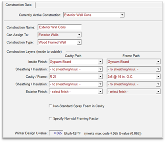
CBECC-Res Software Wall Assembly Construction showing U-0.065 Assembly
Answer 1: Medium-density ccSPF is given a default value of R-5.8 per inch, as per JA4 Table 4.1.7. When 2 inches of ccSPF is added to R-13 batt insulation, the total cavity insulation is rounded to R-25. The assembly U-factor was calculated to be 0.065 using Commission-approved compliance software:
Question 2: Does this assembly meet prescriptive compliance requirements in Climate Zones 6 and 7?
Answer 2: Yes. The assembly does meet the minimum mandatory wall insulation U-factor requirement of 0.071, as well as the prescriptive U-factor requirement of
0.065 in Climate Zones 6 and 7.
Question 3: How about in otherclimate zones?
Answer 3: No. The assembly does not meet the prescriptive compliance U-factor requirement of 0.048 in Climate Zones 1-5 and 8-16 for single-family homes or 0.051 for multifamily buildings. To meet the prescriptive requirement for those climate zones, other wall assemblies may be used, and/or advanced wall ‘system (AWS) techniques may be used to reduce the framing factor. Alternatively, the project may be shown to comply with the Energy Standards using the performance approach. For more on the performance approach, see Section 3.6
2. Mass Walls
Location of Insulation. The prescriptive requirements have separate criteria for mass walls with interior insulation and mass walls with exterior insulation. “Interior” denotes that insulation is installed on the interior surface of the mass wall, and “exterior” denotes that insulation is installed on the exterior surface of the mass wall. Mass walls with insulation applied in locations other than directly to the interior or exterior, such as concrete sandwich panels, must meet the requirements for mass walls with exterior insulation. Mass walls with insulation applied to both the interior and exterior, such as insulated concrete forms (ICF), must meet the requirements for mass walls with interior insulation. Placement of insulation on mass walls will affect the thermal mass properties of a building. When the prescriptive compliance approach is used, the continuous insulation must be installed integral with or on the exterior or interior of the mass wall.
Calculating the U-Factor. To calculate the effective U-factor of a furred wall using the tables in Reference Joint Appendix JA4:
1. Select a U-factor from JA4 Table 4.3.5 (Hollow Unit Masonry) or 4.3.6 (Solid Unit Masonry or Concrete) consistent with the type of wall.
2. Select the appropriate effective R-value for interior or exterior insulation layers from JA4 Table 4.3.14.
3. Use Equation 4-1, and the values selected, to calculate the U-factor of the construction assembly with the continuous insulation.
4. Compare the U-factor; it must be equal to or greater than the mass prescriptive U-factor from Energy Standards Table 150.1-A or Table 150.1-B to comply.
|
|
The U-factor of furred concrete or masonry walls also can be determined by building the construction assembly in Commission-approved compliance software. |
Compliance and Enforcement for Insulation Installation in Framed Assemblies.
Documentation of insulation R-values and assembly U-factors includes product data sheets, manufacturer specifications and installation guidelines, insulation product and assembly testing information, and U-factor calculations following the procedures specified in JA4 or from results of approved performance compliance computer software.
Figure 3-29: Masonry Wall With Furring Details

Source: California Energy Commission
The plans examiner should verify that the insulation R-value for walls (cavity and/or continuous) on the CF1R document is specified on the building plans and compliant with Table 150.1-A or Table 150.1-B.
The building inspector should verify the installed wall insulation meets or exceeds the R-value on the CF1R document.
Batt and loose fill insulation should fill the wall cavity evenly. If kraft or foil-faced insulation is used, it should be installed per manufacturer recommendations to minimize air leakage and avoid sagging of the insulation. Wall insulation should extend into the perimeter floor joist (rim joist) cavities along the same plane as the wall. If a vapor retarder is required, it must be installed on the conditioned space side of the framing.
|
|
Because it is difficult to inspect wall insulation behind tub and shower enclosures after the enclosures are installed, insulation of these wall sections should be inspected during the framing inspection. |
Example 3-26: Minimum Insulation for Block Walls
Question: Do new residential buildings or additions consisting of block walls (for example, converting a garage into living space) have to comply with the R-13 minimum wall insulation requirement? If not, what insulation R-value do they need?
Answer: Block walls are considered masonry walls, and according to §150.0(c)3, the wall must have a U-factor not exceeding that required in Tables 150.1-A or Table 150.1-B.
3.5.5.1 Mandatory Requirements
Wood-framed floors over unconditioned space, regardless of whether there is a crawlspace, must have at least R-19 insulation installed between framing members, or the construction must have a U-factor of 0.037 or less. The equivalent U-factor is based on R-19 insulation in a 2x6, 16 inch on center wood-framed floor with a crawl space.
Other types of raised floors, except for concrete raised floors (concrete raised floors do not have a mandatory requirement, but do have a prescriptive requirement) must also meet the maximum U-factor. In all cases, some areas of the floor can have a U-factor greater than the requirement as long as other areas have a U-factor that is lower than the requirement and the area-weighted average U-factor is less than that described above.
Raised slab floors with radiant heat (heated slab floors) must meet special insulation requirements that are described in Chapter 4 of this manual.
|
|
When a controlled ventilated or an unvented crawlspace is used, raised-floor insulation is not required, although a vapor retarder is required over the ground, and the foundation walls must be insulated. |
3.5.5.2 Prescriptive Requirements
The prescriptive requirements differ for concrete raised floors and wood-framed floors. While the requirements for framed floors are the same in all climate zones, the requirements for concrete raised floors differ.
Framed Raised Floors. Table 150.1-A or Table 150.1-B (prescriptive requirements) call for a minimum of R-19 insulation installed between wood framing or a maximum area-weighted average U-factor of 0.037 for framed raised floors in all climate zones. The requirement may be satisfied by installing the specified amount of insulation in a wood-framed floor or by meeting an equivalent U-factor. U-factors for raised floor assemblies are listed in Reference Joint Appendix JA4.4.
|
R-Value |
Crawlspace? |
Reference Joint Appendix JA4 Construction and Table Cell Entry |
Equivalent U-Factor |
|
R-19 |
No |
4.4.2 A4 |
0.049 |
|
R-19 |
Yes |
4.4.1 A4 |
0.037 |
Concrete Raised Floors. Concrete floors separating multifamily habitable space from a parking garage are also considered a raised floor. Insulation requirements for concrete raised floors differ by climate zone, summarized in Table 3-12.
|
Climate Zone |
1,2,11,13,14,16 |
12,15 |
3-10 |
|
U-Factor |
< 0.092 |
< 0.138 |
< 0.269 |
|
R-Value of Continuous Insulation |
> R-8 |
> R-4 |
No Req. |
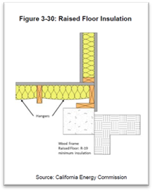
Installation. Floor insulation should be installed in direct contact with the subfloor so that there is no air space between the insulation and the floor. Support is needed to prevent the insulation from falling, sagging, or deteriorating.
Options for support include netting stapled to the underside of floor joists, insulation hangers running perpendicular to the joists, or other suitable means. Insulation hangers should be spaced at 18 inches or less before rolling out the insulation. See Figure 3-30. Insulation hangers are heavy wires up to 48 inches long with pointed ends, which provide positive wood penetration. Netting or mesh should be nailed or stapled to the underside of the joists. Floor insulation should not cover foundation vents.
3.5.6.1 Mandatory Requirements §150.0(f)
Slab Insulation Products
The mandatory requirements state that the insulation material must be suitable for the application. Insulation material in direct contact with soil, such as perimeter insulation, must have a water absorption rate no greater than 0.3 percent when tested in accordance with ASTM C272 Test Method A, 24-Hour Immersion, and a vapor permeance no greater than 2.0 perm/inch when tested in accordance with ASTM E96.
The insulation must be protected from physical and UV degradation by either installing a water-resistant protection board, extending sheet metal flashing below grade, choosing an insulation product that has a hard durable surface on one side, or by other suitable means.
Figure 3-31: Perimeter Slab Insulation

The top of the insulation must be protected with a rigid material to prevent intrusion of insects into the building foundation.
A common location for the slab insulation is on the foundation perimeter (Figure 3-31). Insulation that extends downward to the top of the footing is acceptable. Otherwise, the insulation must extend downward from the level of the top of the slab, down 16 inches (40 cm) or to the frost line, whichever is greater.
For below-grade slabs, vertical insulation shall be extended from the top of the foundation wall to the bottom of the foundation (or the top of the footing) or to the frost line, whichever is greater.
3.5.6.2 Heated Slab Floor Insulation §110.8(g)
Heated slab-on-grade floors must be insulated according to the requirements in Table 110.8-A and Table 3-13.
One option is to install the insulation between the heated slab and foundation wall. In this case, insulation must extend downward to the top of the footing and then extend horizontally inward four feet toward the center of the slab. R-5 vertical insulation is required in all climates except Climate Zone 16, which requires R-10 of vertical insulation and R-7 horizontal insulation.
 Table 3-13: Slab Insulation Requirements for
Heated Slab Floors
Table 3-13: Slab Insulation Requirements for
Heated Slab Floors
|
Insulation Location |
Insulation Orientation |
Installation Requirements |
Climate Zone |
Insulation R-Value |
|
Outside edge of heated slab, either inside or outside the foundation wall |
Vertical |
From the level of the top of the slab, down 16 inches or to the frost line, whichever is greater. Insulation may stop at the top of the footing, where this is less than the required depth. For below-grade slabs, vertical insulation shall be extended from the top of the foundation wall to the bottom of the foundation (or the top of the footing) or to the frost line, whichever is greater. |
1 – 15 |
5 |
|
16 |
10 | |||
|
Between heated slab and outside foundation wall |
Vertical and Horizontal |
Vertical insulation from top of slab at inside edge of outside wall down to the top of the horizontal insulation. Horizontal insulation from the outside edge of the vertical insulation extending 4 feet toward the center of the slab in a direction normal to the outside of the building in plain view. |
1 – 15 |
5 |
|
16 |
10 vertical and 7 horizontal |
3.5.6.3 Prescriptive Requirements
Tables 150.1-A and 150.1-B of the Energy Standards require slab insulation only in Climate Zone 16 for unheated slabs. All heated slabs must meet mandatory insulation requirements in §110.8(g).
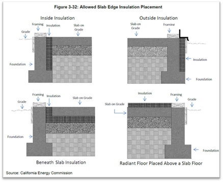
For unheated slabs in Climate Zone 16, a minimum of R-7 slab-edge insulation or a maximum U-factor of 0.58 must be achieved. The insulation must be installed to a minimum depth of 16 inches or to the bottom of the footing, whichever is less. The depth is measured from the top of the insulation, as near the top of slab as ramingpractical, to the bottom edge of the insulation. See Figure 3-32.
|
|
Perimeter insulation is not required along the slab edge between conditioned space and the concrete slab of an attached unconditioned enclosed space such as a garage, covered porch, or covered patio. Neither would it be practical or necessary to insulate concrete steps attached to the outside slab edge. |
Example 3-27: Heated Slab Insulation
Question: What are the slab edge insulation requirements for a hydronic-heating system with the hot water pipes in the slab?
Answer: The requirements for insulation of heated slabs can be found in §110.8(g) of the Energy Standards and are described in Section 3.5.6.1 of this manual. The material and installation specifications are as follows:
1. Insulation values as shown in Table 110.8-A of the Energy Standards
2. Protection from physical damage and UV light deterioration
3. Water absorption rate no greater than 0.3 percent (ASTM C272)
4. Water vapor permeance no greater than 2.0 perm/inch (ASTM E96)
Thermal mass consists of exposed tile floors over concrete, mass walls such as stone or brick, and other heavy elements within the building envelope that stabilizes indoor temperatures. Thermal mass helps temper interior temperature, storing heat or cooling for later use. In California’s Central Valley and desert climates, the summer temperature range between night and day can be 30°F or more, and thermal mass can be an effective strategy to reduce daytime cooling loads.
Mass walls typically fall into two categories:
•Masonry. Masonry includes clay and concrete units, which may be solid or hollow, and glazed or unglazed. Other masonry unit types include cast stone and calcium silicate units. Concrete masonry units (CMU) are made from a mixture of Portland cement and aggregates under controlled conditions. Concrete masonry units can be manufactured in different sizes and with a variety of face textures.
•Concrete and concrete sandwich panels. Concrete and concrete sandwich panels typically use a precast form by casting concrete in a reusable mold or "form" that is then cured in a controlled environment, transported to the construction site, and lifted into place. Precast stone is distinguished from precast concrete by using a fine aggregate in the mixture, giving the appearance of naturally occurring rock or stone.
When thermal mass exists in exterior walls, it stabilizes temperatures in two ways. First, there is a time delay between when the outside temperature of the wall reaches its peak and when the inside of the wall reaches its peak. For an 8-inch to 12-inch concrete wall, this time delay is between 6 to 10 hours. Second, there is a dampening effect whereby the temperature range inside the house is less than the temperature range outside the house. These effects are illustrated in the Figure 3-33.
Figure 3-33: Thermal Mass Performance

Source: California Energy Commission
|
|
When the performance method is used, credit is offered for increasing thermal mass in buildings. This procedure is automated in Energy Commission-approved computer compliance software. See Section 3.6 for the performance method. |
Prescriptive Requirements (Table 150.1-A and Table 150.1-B)
The prescriptive requirements shown in Table 150.1-A and Table 150.1-B call for QII in all climate zones for new construction and additions greater than 700 square feet, except low-rise multifamily buildings in Climate Zone 7.
All insulation shall be installed properly throughout the building. A third-party HERS Rater is required to verify the integrity of the installed insulation. The installer shall provide evidence to the HERS Rater using compliance documentation that all insulation specified is installed to meet specified R-values and assembly U-factors.
To meet QII, two primary installation criteria must be adhered to and they both must be field-verified by a HERS Rater. They include air sealing of the building enclosure (including walls, ceiling/roof, and floors), as well as proper installation of insulation. Refer to Reference Appendices RA3.5 for more details.
|
|
Many residential insulation installations have flaws that degrade thermal performance. Four problems are generally responsible for this degradation: |
|
1. There is an inadequate air barrier in the building envelope or holes and gaps within the air barrier system that inhibit the ability to limit air leakage. 2. Insulation is not in contact with the air barrier, creating air spaces that short-circuit the thermal break of the insulation when the air barrier is not limiting air leakage properly. 3. The insulation has voids or gaps, resulting in portions of the construction assembly that are not properly insulated and, therefore, have less thermal resistance than other portions of the assembly (Figure 3-34). 4. The insulation is compressed, creating a gap near the air barrier and/or reducing the thickness of the insulation. | |
Figure 3-34: Examples of Poor Quality Insulation Installation

QII requires third-party HERS inspection to verify that an air barrier and insulation are installed correctly to eliminate or reduce common problems associated with poor installation. Guidance for QII is provided in Residential Appendix RA3.5. QII applies to framed and nonframed assemblies. Residential construction may incorporate multiple frame types, for example, using a combination of nonframed walls with a framed roof/ceiling. Likewise, multiple insulation materials often are used.
|
Framed Assemblies |
|
Framed assemblies include wood and steel construction insulated with batts of mineral fiber, mineral and natural wool, or cellulose; loose-fill insulation of mineral fiber, mineral and natural wool, cellulose, or spray polyurethane foam (SPF). Rigid board insulation may be used on the exterior or interior of framed or nonframed assemblies. |
|
Nonframed Assemblies |
|
Nonframed assemblies include structural insulated panels (SIP), insulated concrete forms (ICF), and mass walls of masonry, concrete and concrete sandwich panels, log walls, and straw bale. |
|
|
Tips for Implementing QII |
|
Applies to all Insulation |
QII applies to the whole building - roof/ceilings, walls, and floors - and requires field verification by a third-party HERS Rater. |
|
Slab Edge Insulation |
If slab edge insulation is installed, then the integrity of the slab edge insulation must also be field-verified in ‘addition to the air barrier and insulation system for walls and the roof/ceiling. |
|
Various Insulation Types |
Combinations of insulation types (hybrid systems) are allowed. |
|
Air Barriers |
An air barrier shall be installed for the entire envelope. |
|
Additions |
QII is prescriptively required for additions to existing buildings more than 700 square feet. Refer to Chapter 9 for additional information specific to additions. |
|
Alterations |
Compliance credit is allowed for alterations to existing buildings where the “existing, plus addition, plus alteration” approach is used, but credit will only apply to new surfaces in the new zone. |
|
Insulated Headers |
Headers shall meet one of the following criteria for QII: a. Two-member header with insulation in between. The header and insulation must fill the wall cavity. There are prefabricated products available that meet this assembly. Example: a 2x4 wall with two 2x nominal headers, or a 2x6 wall with a 4x nominal header and a 2x nominal header. Insulation is required to fill the wall cavity and must be installed between the headers. b. Two-member header, less than the wall width, with insulation on the interior face. The header and insulation must fill the wall cavity. Example: a 2x6 wall with two 2x nominal headers. Insulation is required to fill the wall cavity and must be installed to the interior face of the wall. c. Single-member header, less than the wall width, with insulation on the interior face. The header and insulation must fill the wall cavity. Example: a 2x4 wall with a 3-1/8-inch-wide header, or 2x6 wall with a 4x nominal header. Insulation is required to fill the wall cavity and must be installed to the interior face of the wall. d. Single-member header, same width as wall. The header must fill the wall cavity. Example: a 2x4 wall with a 4x nominal header or a 2x6 wall with a 6x nominal header. No additional insulation is required because the header fills the cavity. |
|
Panel Box Headers |
Wood structural panel box headers may also be used as load-bearing headers in exterior wall construction, when built in accordance with 2015 CRC Figure R602.7.3 and Table R602.7.3. |
|
Structural Bracing, Tie-Downs, Steel Structural Framing |
Metal bracing, tie-downs, or steel structural framing can be used to connect to wood framing for structural or seismic purposes, and comply with QII if: a. Metal bracing, tie-downs, or steel structural framing is identified on the structural plans. b. Insulation is installed in a manner that minimizes the thermal bridging through the structural framing assembly. c. Insulation fills the entire cavity and/or adheres to all six sides and ends of structural assemblies that separate conditioned from unconditioned space. d. The structural portions of assemblies are airtight. |
QII in the Compliance Modeling Software. QII is not a mandatory requirement; therefore, when using the performance approach, QII may be traded off with other efficiency measures. The compliance modeling software assumes QII and full insulation effectiveness in the standard design. The compliance modeling software automatically reduces the effectiveness of insulation for the proposed design in projects that do not pursue QII. The effect of a poorly installed air barrier system and envelope insulation results in higher wall heat loss and heat gain than standard R-value and U-factor calculations would indicate. Similar increases in heat loss and heat gain are experienced for roof/ceilings where construction and installation flaws are present. The reduction in effectiveness reflects standard industry installation practices and allows for full insulation credit to be taken for HERS verified quality insulation installation.
3.5.8.1 Air Barrier RA3.5.2
An air barrier shall be installed enclosing the entire building. The air barrier must be installed in a continuous manner across all components of framed and nonframed envelope assemblies. The installer shall provide evidence with compliance documentation that the air barrier system meets one or more of the air barrier requirements. More detailed explanation is provided in RA3.5. Documentation for the air barrier includes product data sheets and manufacturer specifications and installation guidelines.
|
|
For QII, a third-party HERS Rater is required to verify that the air barrier has been installed properly and is integral with the insulation being used throughout the building. |
|
|
Continuous Air Barrier Requirements |
|
A combination of interconnected materials and assemblies are joined and sealed together to provide a continuous barrier to air leakage through the building envelope separating conditioned from unconditioned space, or adjoining conditioned spaces of different occupancies or uses. An air barrier must meet one of the following: | |
|
1. Using materials that have an air permeance not exceeding 0.004 cfm/ft2 under a pressure differential of 0.3 in. w.g. (1.57 psf) (0.02 L/s.m2 at 75 pa) when tested in accordance with ASTM E2178. 2. Using assemblies of materials and components that have an average air leakage not to exceed 0.04 cfm/ft2 under a pressure differential of 0.3 in. w.g (1.57 psf) (0.2 L/s.m2 at 75 pa) when tested in accordance with ASTM E2357, ASTM E1677, ASTM E1680 or ASTM E283. 3. Testing the completed building and demonstrating that the air leakage rate of the building envelope does not exceed 0.40 cfm/ft2 at a pressure differential of 0.3 in w.g. (1.57 psf) (2.0 L/s.m2 at 75 pa) in accordance with ASTM E779 or an equivalent approved method. | |
|
The following materials meet the air permeance testing performance levels of 1 above. Manufacturers of these and other product types must provide a specification or product data sheet showing compliance to the ASTM testing requirements to be considered as an air barrier. | |
|
•Plywood – minimum 3/8 inch •Oriented strand board – minimum 3/8 inches •Extruded polystyrene insulation board – minimum 1/2 inch •Foil-backed polyisocyanurate insulation board – minimum 1/2 inch •Foil-backed urethane foam insulation – 1 inch •Closed-cell spray polyurethane foam (ccSPF) with a minimum density of 2.0 pcf and a minimum thickness of 2.0 inches. Alternatively, ccSPF insulation shall be installed at a thickness that meets an air permeance no greater than 0.02 L/s-m2 at 75 Pa pressure differential when tested in accordance to ASTM E2178 or ASTM E283. •Open cell spray polyurethane (ocSPF) foam with a minimum density of 0.4 to1.5 pcf and a minimum thickness of 5½ inches. Alternatively, ocSPF insulation shall be installed at a thickness that meets an air permeance no greater than 0.02 L/s-m2 at 75 Pa pressure differential when tested in accordance to ASTM E2178 or ASTM E283. •Exterior or interior gypsum board – minimum 1/2 inch •Cement board – minimum 1/2 inch •Built-up roofing membrane •Modified bituminous roof membrane •Particleboard – minimum 1/2 inch •Fully adhered single-ply roof membrane •Portland cement/sand parge, or gypsum plaster – minimum 5/8 inch •Cast-in-place and precast concrete •Fully grouted uninsulated and insulated concrete block masonry •Sheet steel or aluminum | |
|
Materials and assemblies of materials that can demonstrate compliance with the air barrier testing requirements must be installed according to the manufacturer's instructions, and a HERS Rater shall verify the integrity of the installation. | |
Source: California Energy Commission


