Rated R-value of Continuous Insulation | |||||||||||
Framing Spacing | Nominal Framing Size | R-Value Cavity Insul. | R-0 | R-2 | R-4 | R-6 | R-7 | R-8 | R-10 | R-14 | |
A | B | C | D | E | F | G | H | ||||
16 in. OC | Any 2 x 6 | None | 1 | 0.097 | 0.081 | 0.070 | 0.061 | 0.058 | 0.055 | 0.049 | 0.041 |
R-11 | 2 | 0.049 | 0.045 | 0.041 | 0.038 | 0.037 | 0.035 | 0.033 | 0.029 | ||
R-13 | 3 | 0.046 | 0.042 | 0.039 | 0.036 | 0.035 | 0.033 | 0.031 | 0.028 | ||
R-19 | 4 | 0.037 | 0.034 | 0.032 | 0.030 | 0.029 | 0.029 | 0.027 | 0.024 | ||
2 x 8 | R-19 | 5 | 0.037 | 0.034 | 0.032 | 0.030 | 0.029 | 0.029 | 0.027 | 0.024 | |
R-22 | 6 | 0.034 | 0.032 | 0.030 | 0.028 | 0.027 | 0.027 | 0.025 | 0.023 | ||
2 x 10 | R-25 | 7 | 0.031 | 0.029 | 0.028 | 0.026 | 0.025 | 0.025 | 0.024 | 0.022 | |
R-30 | 8 | 0.028 | 0.026 | 0.025 | 0.024 | 0.023 | 0.023 | 0.022 | 0.020 | ||
2 x 12 | R-38 | 9 | 0.024 | 0.023 | 0.022 | 0.021 | 0.020 | 0.020 | 0.019 | 0.018 | |
24 in. OC | Any 2 x 6 | None | 10 | 0.098 | 0.082 | 0.070 | 0.062 | 0.058 | 0.055 | 0.049 | 0.041 |
R-11 | 11 | 0.049 | 0.045 | 0.041 | 0.038 | 0.036 | 0.035 | 0.033 | 0.029 | ||
R-13 | 12 | 0.045 | 0.041 | 0.038 | 0.035 | 0.034 | 0.033 | 0.031 | 0.028 | ||
R-19 | 13 | 0.037 | 0.034 | 0.032 | 0.030 | 0.029 | 0.028 | 0.027 | 0.024 | ||
2 x 8 | R-19 | 14 | 0.036 | 0.034 | 0.032 | 0.030 | 0.029 | 0.028 | 0.027 | 0.024 | |
R-22 | 15 | 0.033 | 0.031 | 0.029 | 0.028 | 0.027 | 0.026 | 0.025 | 0.023 | ||
2 x 10 | R-25 | 16 | 0.030 | 0.029 | 0.027 | 0.026 | 0.025 | 0.024 | 0.023 | 0.021 | |
R-30 | 17 | 0.027 | 0.026 | 0.024 | 0.023 | 0.023 | 0.022 | 0.021 | 0.020 | ||
2 x 12 | R-38 | 18 | 0.023 | 0.022 | 0.021 | 0.020 | 0.020 | 0.020 | 0.019 | 0.017 | |
Notes:
1. In order to use the U-factors listed in this section, exterior raised-floor insulation shall be installed between floor joists with a means of support that prevents the insulation from falling, sagging or deteriorating. Two approaches that accomplish this are:
2. Nailing insulation hangers 18 inches apart prior to rolling out the insulation. Hangers are heavy wires up to 48 inches long with pointed ends, which provide positive wood penetration.
3. Attaching wire mesh to form a basket between joists to support the insulation. Mesh is nailed or stapled to the underside of the joists.
This table contains U-factors for wood framed floors built over a ventilated crawlspace. This construction is common for low-rise residential buildings and for Type IV nonresidential buildings.
If continuous insulation is not used, then choices are made from Column A. In this case, the insulation is installed only between the framing members. Continuous insulation is not common for wood floors over a crawlspace, but if credit is taken, the insulation may be installed either above or below the framing members. The continuous insulation is typically a rigid polystyrene or polyisocyanurate foam insulation.
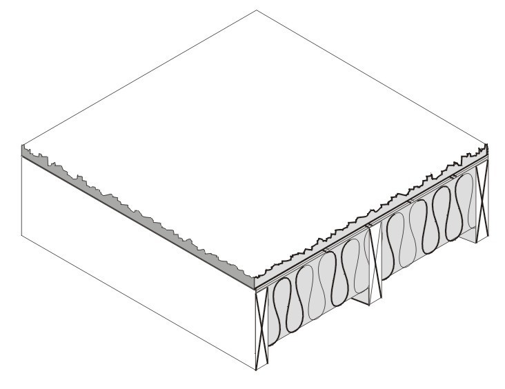
Figure 4.4.1 – Wood Framed Floor with a Crawl Space
When this table is used manually, the R-value of continuous insulation shall be equal to or greater than the R-value published in the continuous insulation columns. Continuous insulation of at least R-2 must exist in order to use columns B and beyond. No interpolation is permitted when data from the table is used manually. Commission approved compliance software, however, may determine the U-factor for any amount of continuous insulation or for unusual construction assemblies using Equation 4-1 and Equation 4-2.
If the crawlspace is not ventilated and is modeled as a controlled ventilation crawlspace (CVC), then values from this table shall not be used. Values from Table 4.21 shall be used instead and the crawlspace shall be modeled as a separate and unconditioned zone.
Assumptions: Calculations use the ASHRAE parallel heat flow method documented in the 2005 ASHRAE Handbook of Fundamentals. These calculations assume an exterior air film of R-0.17, a vented crawlspace for an effective R-6, a continuous insulation layer (if any), the insulation / framing layer, 5/8 inch wood based sheathing (Custom), carpet and pad of R-2.08 (CP01), and an interior air film (heat flow down) of R-0.92. The framing factor is assumed to be 10 percent for 16 inch stud spacing and 7 percent for 24 inch spacing.
Spacing | Nominal Framing Size | R-Value of Cavity Insul. | Rated R-value of Continuous Insulation | ||||||||
R-0 | R-2 | R-4 | R-6 | R-7 | R-8 | R-10 | R-14 | ||||
A | B | C | D | E | F | G | H | ||||
16 in. OC | Any | None | 1 | 0.238 | 0.161 | 0.122 | 0.098 | 0.089 | 0.082 | 0.070 | 0.055 |
2 x 6 | R-11 | 2 | 0.071 | 0.062 | 0.055 | 0.050 | 0.047 | 0.045 | 0.041 | 0.036 | |
(5.50 in) | R-13 | 3 | 0.064 | 0.057 | 0.051 | 0.046 | 0.044 | 0.042 | 0.039 | 0.034 | |
R-19 | 4 | 0.049 | 0.044 | 0.040 | 0.037 | 0.036 | 0.035 | 0.032 | 0.028 | ||
2 x 8 | R-19 | 5 | 0.048 | 0.044 | 0.040 | 0.037 | 0.036 | 0.035 | 0.033 | 0.029 | |
(7.25 in.) | R-22 | 6 | 0.044 | 0.040 | 0.037 | 0.035 | 0.033 | 0.032 | 0.030 | 0.027 | |
2 x 10 | R-25 | 7 | 0.039 | 0.036 | 0.034 | 0.031 | 0.030 | 0.030 | 0.028 | 0.025 | |
(9.25 in.) | R-30 | 8 | 0.034 | 0.032 | 0.030 | 0.028 | 0.028 | 0.027 | 0.025 | 0.023 | |
2 x 12 | R-38 | 9 | 0.029 | 0.027 | 0.026 | 0.024 | 0.024 | 0.023 | 0.022 | 0.020 | |
(11.25 in.) | |||||||||||
24 in. OC | Any | None | 10 | 0.243 | 0.163 | 0.123 | 0.099 | 0.090 | 0.083 | 0.071 | 0.055 |
2 x 6 | R-11 | 11 | 0.070 | 0.061 | 0.054 | 0.049 | 0.047 | 0.045 | 0.041 | 0.035 | |
(5.50 in.) | R-13 | 12 | 0.062 | 0.055 | 0.050 | 0.045 | 0.043 | 0.042 | 0.038 | 0.033 | |
R-19 | 13 | 0.047 | 0.043 | 0.039 | 0.037 | 0.035 | 0.034 | 0.032 | 0.028 | ||
2 x 8 | R-19 | 14 | 0.047 | 0.043 | 0.039 | 0.037 | 0.035 | 0.034 | 0.032 | 0.028 | |
(7.25 in.) | R-22 | 15 | 0.042 | 0.039 | 0.036 | 0.034 | 0.033 | 0.032 | 0.030 | 0.026 | |
2 x 10 | R-25 | 16 | 0.037 | 0.035 | 0.033 | 0.031 | 0.030 | 0.029 | 0.027 | 0.025 | |
(9.25 in.) | R-30 | 17 | 0.033 | 0.031 | 0.029 | 0.027 | 0.027 | 0.026 | 0.025 | 0.022 | |
2 x 12 | R-38 | 18 | 0.027 | 0.026 | 0.025 | 0.023 | 0.023 | 0.022 | 0.021 | 0.020 | |
(11.25 in.) | |||||||||||
This table contains U-factors for wood framed floors that are exposed to ambient (outdoor) conditions. This construction is common for low-rise residential buildings and for Type 4 nonresidential buildings.
If continuous insulation is not used, then choices are made from Column A. In this case, the insulation is installed only between the framing members. If credit is taken for continuous insulation, the insulation may be installed either above or below the framing members.
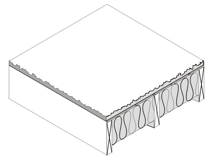
Figure 4.4.2 – Wood Framed Floor without a Crawl SpaceFigure
When this table is used manually, the R-value of continuous insulation shall be equal to or greater than the R-value published in the continuous insulation columns. No interpolation is permitted when data from the table is used manually. Commission approved compliance software, however, may determine the U-factor for any amount of continuous insulation or for unusual construction assemblies using Equation 4-1 and Equation 4-2.
Assumptions: Calculations use the ASHRAE parallel heat flow method documented in the 2009 ASHRAE Handbook of Fundamentals. These calculations assume an exterior air film of R-0.17, a continuous insulation layer (if any), the cavity insulation / framing layer, 5/8 inch wood based sheathing (Custom), carpet and pad of R-2.08 (CP01), and an interior air film (heat flow down) of R-0.92.
Crawlspace | Insulation R-value1 | Wood Framing Spline Connection Type (Splines) | Typical Panel Thickness | Rated R-value of Continuous Insulation3 | |||||||||||||||||||
None | R-2 | R-4 | R-6 | R-7 | R-8 | R-10 | |||||||||||||||||
A | B | C | D | E | F | G | |||||||||||||||||
YES | R-22 | Single 2x | 6.5 in | 1 | 0.033 | 0.030 | 0.029 | 0.027 | 0.026 | 0.026 | 0.024 | ||||||||||||
R-22 | Double 2x | 6.5 in | 2 | 0.034 | 0.031 | 0.029 | 0.028 | 0.027 | 0.026 | 0.025 | |||||||||||||
R-22 | I-Joist | 6.5 in | 3 | 0.032 | 0.030 | 0.028 | 0.027 | 0.026 | 0.025 | 0.024 | |||||||||||||
R-28 | Single 2x | 8.25 in | 4 | 0.027 | 0.026 | 0.024 | 0.023 | 0.023 | 0.022 | 0.021 | |||||||||||||
R-28 | Double 2x | 8.25 in | 5 | 0.028 | 0.026 | 0.025 | 0.024 | 0.023 | 0.023 | 0.022 | |||||||||||||
R-28 | I-Joist | 8.25 in | 6 | 0.027 | 0.025 | 0.024 | 0.023 | 0.022 | 0.022 | 0.021 | |||||||||||||
R-332 | Single 2x | 6.5 in | 7 | 0.024 | 0.023 | 0.022 | 0.021 | 0.021 | 0.020 | 0.019 | |||||||||||||
R-332 | Double 2x | 6.5 in | 8 | 0.026 | 0.024 | 0.023 | 0.022 | 0.021 | 0.021 | 0.020 | |||||||||||||
R-3 2 | I-Joist | 6.5 in | 9 | 0.024 | 0.023 | 0.022 | 0.021 | 0.020 | 0.020 | 0.019 | |||||||||||||
R-36 | Single 2x | 10.25 in | 10 | 0.023 | 0.022 | 0.021 | 0.020 | 0.019 | 0.019 | 0.018 | |||||||||||||
R-36 | Double 2x | 10.25 in | 11 | 0.024 | 0.022 | 0.021 | 0.020 | 0.020 | 0.020 | 0.019 | |||||||||||||
R-36 | I-Joist | 10.25 in | 12 | 0.022 | 0.021 | 0.020 | 0.019 | 0.019 | 0.019 | 0.018 | |||||||||||||
NO | R-22 | Single 2x | 6.5 in | 13 | 0.041 | 0.038 | 0.035 | 0.033 | 0.031 | 0.030 | 0.029 | ||||||||||||
R-22 | Double 2x | 6.5 in | 14 | 0.043 | 0.039 | 0.036 | 0.034 | 0.032 | 0.031 | 0.029 | |||||||||||||
R-22 | I-Joist | 6.5 in | 15 | 0.040 | 0.037 | 0.034 | 0.032 | 0.031 | 0.030 | 0.028 | |||||||||||||
R-28 | Single 2x | 8.25 in | 16 | 0.033 | 0.030 | 0.029 | 0.027 | 0.026 | 0.026 | 0.024 | |||||||||||||
R-28 | Double 2x | 8.25 in | 17 | 0.034 | 0.032 | 0.030 | 0.028 | 0.027 | 0.026 | 0.025 | |||||||||||||
R-28 | I-Joist | 8.25 in | 18 | 0.032 | 0.030 | 0.028 | 0.027 | 0.026 | 0.025 | 0.024 | |||||||||||||
R-332 | Single 2x | 6.5 in | 19 | 0.029 | 0.027 | 0.026 | 0.024 | 0.024 | 0.023 | 0.022 | |||||||||||||
R-332 | Double 2x | 6.5 in | 20 | 0.032 | 0.029 | 0.027 | 0.026 | 0.025 | 0.024 | 0.023 | |||||||||||||
R-332 | I-Joist | 6.5 in | 21 | 0.028 | 0.027 | 0.025 | 0.024 | 0.023 | 0.023 | 0.022 | |||||||||||||
R-36 | Single 2x | 10.25 in | 22 | 0.026 | 0.025 | 0.024 | 0.023 | 0.022 | 0.022 | 0.021 | |||||||||||||
R-36 | Double 2x | 10.25 in | 23 | 0.028 | 0.026 | 0.025 | 0.024 | 0.023 | 0.022 | 0.021 | |||||||||||||
R-36 | I-Joist | 10.25 in | 24 | 0.026 | 0.024 | 0.023 | 0.022 | 0.021 | 0.021 | 0.020 | |||||||||||||
Notes:
1. The insulation R-value must be at least R-21.7 in order to use this table. This table assumes molded expanded polystyrene (EPS) unless noted otherwise. Although other insulation types are used by some SIP manufacturers, such as polyurethane and extruded expanded insulation (XPS), EPS is the most common insulation used in SIP construction.
2. R-33.2 is achievable using polyurethane insulation in 6.5" panels.
3. Continuous insulation shall be at least R-2 and may be installed on either the inside or the exterior of the roof/ceiling.
Structural insulated panels (SIPs) consist of a rigid insulation core, securely bonded between two structural facings, to form a structural sandwich panel. SIPs are considered a non-framed assembly usually with little or no structural framing that penetrates the insulation layer, resulting in less thermal bridging across the insulation when compared to a conventional framed assembly.
If continuous insulation is not used, then choices are made from Column A. When continuous insulation is also used, this is typically installed on the exterior side of the floor, but can also be used on the inside. The continuous insulation is typically a rigid polystyrene or polyisocyanurate foam insulation.
When this table is used manually, the R-value of continuous insulation shall be equal to or greater than the R-value published in the continuous insulation columns. Commission approved compliance software, however, may determine the U-factor for any amount of continuous insulation or for unusual construction assemblies using Equation 4-1 and Equation 4-2.
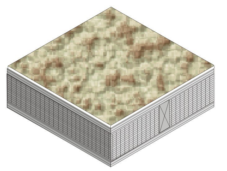
Figure 4.4.3 – Wood Foam Panel (SIP) Floor
Assumptions: These data are calculated using the parallel path method documented in the 2009 ASHRAE Handbook of Fundamentals. These calculations assume an exterior air film of R-0.17, a vented crawlspace of R-6, 7/16 inch of OSB at R-0.44, framing factor of 2%, 7/16 inch of OSB, carpet and pad of R-2.08 and an interior air film of R-0.92.
Framing Spacing | Nominal Framing Size | Cavity Insulation R-Value: | Rated R-value of Continuous Insulation | ||||||||
R-0 | R-2 | R-4 | R-6 | R-7 | R-8 | R-10 | R-14 | ||||
A | B | C | D | E | F | G | H | ||||
16 in. OC | 1 | 0.094 | 0.079 | 0.068 | 0.060 | 0.057 | 0.054 | 0.048 | 0.041 | ||
2 x 6 | R-11 | 2 | 0.065 | 0.058 | 0.052 | 0.047 | 0.045 | 0.043 | 0.039 | 0.034 | |
R-13 | 3 | 0.063 | 0.056 | 0.050 | 0.046 | 0.044 | 0.042 | 0.039 | 0.033 | ||
R-19 | 4 | 0.059 | 0.053 | 0.048 | 0.044 | 0.042 | 0.040 | 0.037 | 0.032 | ||
2 x 8 | R-19 | 5 | 0.058 | 0.052 | 0.047 | 0.043 | 0.041 | 0.040 | 0.037 | 0.032 | |
R-22 | 6 | 0.056 | 0.050 | 0.046 | 0.042 | 0.040 | 0.039 | 0.036 | 0.031 | ||
2 x 10 | R-30 | 7 | 0.051 | 0.046 | 0.042 | 0.039 | 0.038 | 0.036 | 0.034 | 0.030 | |
2 x 12 | R-38 | 8 | 0.048 | 0.044 | 0.040 | 0.037 | 0.036 | 0.035 | 0.032 | 0.029 | |
24 in. OC | Any | None | 9 | 0.094 | 0.079 | 0.068 | 0.060 | 0.057 | 0.054 | 0.048 | 0.041 |
2 x 6 | R-11 | 10 | 0.061 | 0.054 | 0.049 | 0.045 | 0.043 | 0.041 | 0.038 | 0.033 | |
R-13 | 11 | 0.058 | 0.052 | 0.047 | 0.043 | 0.041 | 0.040 | 0.037 | 0.032 | ||
R-19 | 12 | 0.053 | 0.048 | 0.044 | 0.040 | 0.039 | 0.037 | 0.035 | 0.030 | ||
2 x 8 | R-19 | 13 | 0.051 | 0.046 | 0.042 | 0.039 | 0.038 | 0.036 | 0.034 | 0.030 | |
R-22 | 14 | 0.049 | 0.045 | 0.041 | 0.038 | 0.036 | 0.035 | 0.033 | 0.029 | ||
2 x 10 | R-30 | 15 | 0.045 | 0.041 | 0.038 | 0.035 | 0.034 | 0.033 | 0.031 | 0.028 | |
2 x 12 | R-38 | 16 | 0.041 | 0.038 | 0.035 | 0.033 | 0.032 | 0.031 | 0.029 | 0.026 | |
Notes:
In order to use the U-factors listed in this table, exterior raised-floor insulation shall be installed between floor joists with a means of support that prevents the insulation from falling, sagging or deteriorating. Two approaches that accomplish this are:
1. Attaching insulation hangers 18 inches apart prior to rolling out the insulation. Hangers are heavy wires up to 48 inches long with pointed ends.
2. Attaching wire mesh to form a basket between joists to support the insulation. Mesh is nailed or stapled to the underside of the joists.
This table contains U-factors for metal-framed floors built over a crawlspace. The constructions represented are similar to those in Table 4.4.1, except that wood framing is replaced with metal framing. Cavity insulation is installed between the framing members. Since the steel is not as large a cross section as wood, the insulation needs to be wider than that used with wood to fit in between the steel framing members.
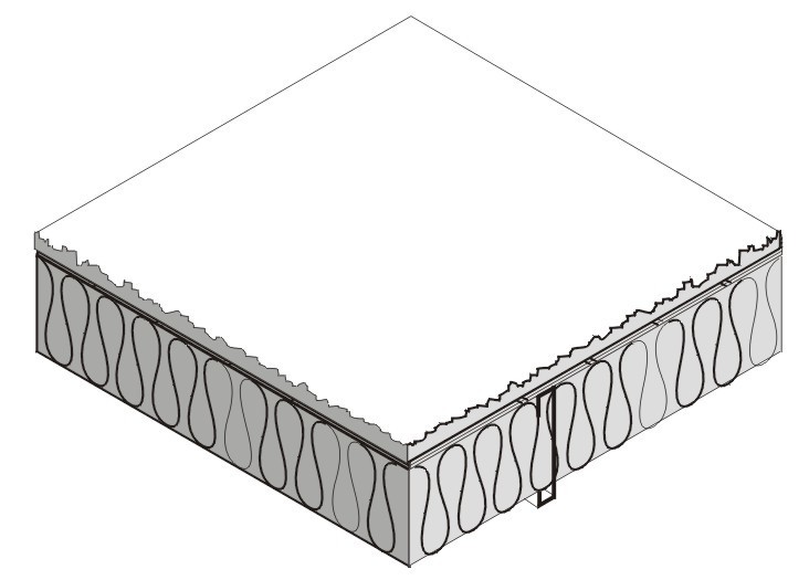
Figure 4.4.4 – Metal Framed Floors with a Crawl Space
For the majority of cases, values will be selected from column A of this table. Column A applies for the common situation where batt insulation is supported between framing members. Builders or designers may increase thermal performance by adding a continuous insulation layer either above or below the framing members.
When this table is used manually, the R-value of continuous insulation shall be equal to or greater than the R-value published in the continuous insulation columns. No interpolation is permitted when data from the table is used manually. Commission approved compliance software, however, may determine the U-factor for any amount of continuous insulation and for unusual construction layers using Equation 4-1 and Equation 4-2.
Assumptions: Calculations are based on the ASHRAE Zone Method Calculation, 2009 ASHRAE Handbook of Fundamentals These calculations assume an exterior air film of R-0.17, a vented crawlspace for an effective R-6, a continuous insulation layer (if any), the insulation / framing layer, 5/8 inch wood based sheathing (Custom), carpet and pad of R-2.08 (CP01), and an interior air film (heat flow down) of R-0.92. The effect of the crawlspace is approximated by an additional R-6 of insulation. The internal default framing percentages are 10 percent for 16 inch on center and 7 percent for 24 inch on center. Steel Framing has a 1.5 inch flange and is 0.075 inch thick steel (14 gauge) with no knockouts. U-factors are calculated using EZ frame 2.0.
Spacing | Nominal Framing Size | Cavity Insulation R-Value | Rated R-value of Continuous Insulation | ||||||||
R-0 | R-2 | R-4 | R-6 | R-7 | R-8 | R-10 | R-14 | ||||
A | B | C | D | E | F | G | H | ||||
16 in. OC | Any | None | 1 | 0.253 | 0.168 | 0.126 | 0.100 | 0.091 | 0.084 | 0.072 | 0.056 |
2 x 6 | R-11 | 2 | 0.108 | 0.089 | 0.075 | 0.066 | 0.062 | 0.058 | 0.052 | 0.043 | |
R-13 | 3 | 0.102 | 0.085 | 0.072 | 0.063 | 0.060 | 0.056 | 0.050 | 0.042 | ||
R-19 | 4 | 0.092 | 0.078 | 0.067 | 0.059 | 0.056 | 0.053 | 0.048 | 0.040 | ||
2 x 8 | R-19 | 5 | 0.088 | 0.075 | 0.065 | 0.058 | 0.054 | 0.052 | 0.047 | 0.039 | |
R-22 | 6 | 0.085 | 0.073 | 0.063 | 0.056 | 0.053 | 0.051 | 0.046 | 0.039 | ||
2 x 10 | R-30 | 7 | 0.075 | 0.065 | 0.058 | 0.052 | 0.049 | 0.047 | 0.043 | 0.037 | |
2 x 12 | R-38 | 8 | 0.068 | 0.060 | 0.053 | 0.048 | 0.046 | 0.044 | 0.040 | 0.035 | |
24 in. OC | Any | None | 9 | 0.253 | 0.168 | 0.126 | 0.100 | 0.091 | 0.084 | 0.072 | 0.056 |
2 x 6 | R-11 | 10 | 0.095 | 0.080 | 0.069 | 0.061 | 0.057 | 0.054 | 0.049 | 0.041 | |
R-13 | 11 | 0.087 | 0.074 | 0.065 | 0.057 | 0.054 | 0.051 | 0.047 | 0.039 | ||
R-19 | 12 | 0.077 | 0.067 | 0.059 | 0.053 | 0.050 | 0.048 | 0.044 | 0.037 | ||
2 x 8 | R-19 | 13 | 0.074 | 0.064 | 0.057 | 0.051 | 0.049 | 0.046 | 0.043 | 0.036 | |
R-22 | 14 | 0.07 | 0.061 | 0.055 | 0.049 | 0.047 | 0.045 | 0.041 | 0.035 | ||
2 x 10 | R-30 | 15 | 0.061 | 0.054 | 0.049 | 0.045 | 0.043 | 0.041 | 0.038 | 0.033 | |
2 x 12 | R-38 | 16 | 0.054 | 0.049 | 0.044 | 0.041 | 0.039 | 0.038 | 0.035 | 0.031 | |
Notes:
In order to use the U-factors listed in this section, exterior raised-floor insulation shall be installed between floor joists with a means of support that prevents the insulation from falling, sagging or deteriorating. Two approaches that accomplish this are:
1. Attaching insulation hangers 18 inches apart prior to rolling out the insulation. Hangers are heavy wires up to 48 inches long with pointed ends.
2. Attaching wire mesh to form a basket between joists to support the insulation. Mesh is nailed or stapled to the underside of the joists.
This table contains U-factors for metal-framed floors built over outdoor conditions. For the majority of cases, values will be selected from column A of this table. Column A applies for the common situation where batt insulation is supported between framing members. Builders or designers may increase thermal performance by adding a continuous insulation layer either above or below the framing members.
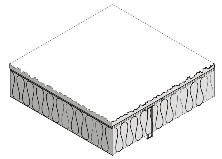
Figure 4.4.5 – Metal Framed Floors without a Crawl Space
When this table is used manually, the R-value of continuous insulation shall be equal to or greater than the R-value published in the continuous insulation columns. No interpolation is permitted when data from the table is used manually. Commission approved compliance software, however, may determine the U-factor for any amount of continuous insulation and for unusual construction layers using Equation 4-1 and Equation 4-2.
Assumptions: Calculations are based on the ASHRAE Zone Method Calculation, 2009 ASHRAE Handbook of Fundamentals Handbook. These calculations assume an exterior air film of R-0.17, a continuous insulation layer (if any), the insulation / framing layer, 5/8 inch wood based sheathing (Custom), carpet and pad of R-2.08 (CP01), and an interior air film (heat flow down) of R-0.92. The internal default framing percentages are 10 percent for 16 inch on center and 7 percent for 24 inch on center. Steel Framing has a 1.5 inch flange and is 0.075 inch thick steel with no knockouts. U-factors calculated using EZ frame 2.0.
R-value of Insulation | Rated R-value of Continuous Insulation | |||
Continuous Insulation Underneath | Continuous Insulation Above Deck1 with no Sleepers | Continuous Insulation Above Deck1 with Sleepers | ||
A | B | C | ||
R-0 | 1 | 0.269 | 0.234 | 0.229 |
R-2 | 2 | 0.183 | 0.159 | 0.157 |
R-4 | 3 | 0.138 | 0.121 | 0.120 |
R-6 | 4 | 0.111 | 0.097 | 0.097 |
R-8 | 5 | 0.092 | 0.081 | 0.081 |
R-10 | 6 | 0.079 | 0.070 | 0.070 |
R-12 | 7 | 0.069 | 0.061 | 0.061 |
R-15 | 8 | 0.058 | 0.052 | 0.052 |
R-20 | 9 | 0.045 | 0.041 | 0.041 |
R-25 | 10 | 0.037 | 0.034 | 0.034 |
R-30 | 11 | 0.031 | 0.029 | 0.029 |
Notes:
1. Above deck case includes a 5/8 inch layer of plywood between the insulation and the carpet and pad. This table may be used only if the HC of the proposed design floor is greater than or equal to 7.0 Btu/ft²-ºF.
Continuous Insulation Underneath
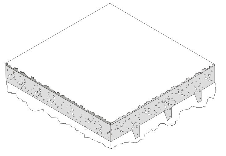
Continuous Insulation Above Deck
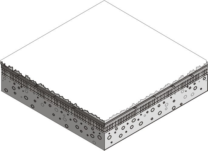
Figure 4.4.6 – Concrete Raised Floors
Assumptions: These calculations assume an exterior air film of R-0.17, a continuous insulation layer (if any), 4 inches of the lightweight concrete (CC14) over metal deck R-0, a continuous insulation layer (if any), 1.5 x 3.5 inch sleeper of R-0.99 per inch, R-0.80 air space between sleepers (2005 ASHRAE Handbook of Fundamentals, Chapter 25, Table 3), 5/8 inches of wood based sheathing (Custom) (if continuous insulation above deck), carpet and pad of R-2.08 (CP01), and an interior air film (heat flow down) of R-0.92. Sleepers have 10 percent framing factor. Below slab insulation assumes 6 inch wide beams 96 inches on center extending 8 inches below the slab.
Insulation Description | Rated R-Value of Insulation | |||||||||||||
R-0 | R-5 | R-7.5 | R-10 | R-15 | R-20 | R-25 | R-30 | R-35 | R-40 | R-45 | R-50 | R-55 | ||
A | B | C | D | E | F | G | H | I | J | K | L | M | ||
None | 1 | 0.73 | ||||||||||||
12 in. horizontal | 2 | 0.72 | 0.71 | 0.71 | 0.71 | |||||||||
24 in. horizontal | 3 | 0.70 | 0.70 | 0.70 | 0.69 | |||||||||
36 in. horizontal | 4 | 0.68 | 0.67 | 0.66 | 0.66 | |||||||||
48 in. horizontal | 5 | 0.67 | 0.65 | 0.64 | 0.63 | |||||||||
12 in. vertical | 6 | 0.61 | 0.60 | 0.58 | 0.57 | 0.567 | 0.565 | 0.564 | ||||||
24 in. vertical | 7 | 0.58 | 0.56 | 0.54 | 0.52 | 0.510 | 0.505 | 0.502 | ||||||
36 in. vertical | 8 | 0.56 | 0.53 | 0.51 | 0.48 | 0.472 | 0.464 | 0.460 | ||||||
48 in. vertical | 9 | 0.54 | 0.51 | 0.48 | 0.45 | 0.434 | 0.424 | 0.419 | ||||||
Fully insulated slab | 10 | 0.46 | 0.41 | 0.36 | 0.30 | 0.261 | 0.233 | 0.213 | 0.198 | 0.186 | 0.176 | 0.168 | 0.161 | |
Note: These values are used for slab edge conditions with and without carpet.
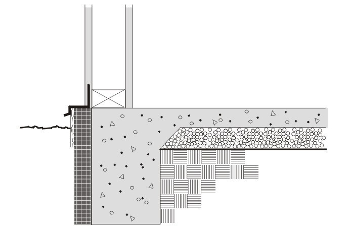
Figure 4.4.7 – Unheated Slab-on-Grade Floor
Horizontal insulation is continuous insulation that is applied directly to the underside of the slab and extends inward horizontally from the perimeter for the distance specified or continuous insulation that is applied downward from the top of the slab and then extends horizontally to the interior or the exterior from the perimeter for the distance specified. Vertical insulation is continuous insulation that is applied directly to the slab exterior, extending downward from the top of the slab for the distance specified. Fully insulated slab is continuous insulation that extends downward from the top to the slab and along the entire perimeter and completely covers the entire area under the slab.
Assumptions: Data of this table is taken from the ASHRAE/IESNA Standard 90.1-2004, Appendix A.
Rated R-Value of Insulation | ||||||||||||||
R-0 | R-5 | R-7.5 | R-10 | R-15 | R-20 | R-25 | R-30 | R-35 | R-40 | R-45 | R-50 | R-55 | ||
A | B | C | D | E | F | G | H | I | J | K | L | M | ||
None | 11 | 1.35 | ||||||||||||
12 in. horizontal | 12 | 1.31 | 1.31 | 1.30 | 1.30 | |||||||||
24 in. horizontal | 13 | 1.28 | 1.27 | 1.26 | 1.25 | |||||||||
36 in. horizontal | 14 | 1.24 | 1.21 | 1.20 | 1.18 | |||||||||
48 in. horizontal | 15 | 1.20 | 1.17 | 1.13 | 1.11 | |||||||||
12 in. vertical | 16 | 1.06 | 1.02 | 1.00 | 0.98 | 0.968 | 0.964 | 0.961 | ||||||
24 in. vertical | 17 | 0.99 | 0.95 | 0.90 | 0.86 | 0.843 | 0.832 | 0.827 | ||||||
36 in. vertical | 18 | 0.95 | 0.89 | 0.84 | 0.79 | 0.762 | 0.747 | 0.740 | ||||||
48 in. vertical | 19 | 0.91 | 0.85 | 0.78 | 0.72 | 0.688 | 0.671 | 0.659 | ||||||
Fully insulated slab | 20 | 0.74 | 0.64 | 0.55 | 0.44 | 0.373 | 0.326 | 0.296 | 0.273 | 0.255 | 0.239 | 0.227 | 0.217 | |
Note: These values are used for slab edge conditions with and without carpet.
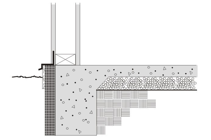
Figure 4.4.8 – Heated Slab-on-Grade Floor
Horizontal insulation is continuous insulation that is applied directly to the underside of the slab and extends inward horizontally from the perimeter for the distance specified or continuous insulation that is applied downward from the top of the slab and then extending horizontally to the interior or the exterior from the perimeter for the distance specified. Vertical insulation is continuous insulation that is applied directly to the slab exterior, extending downward from the top of the slab for the distance specified. Fully insulated slab is continuous insulation that extends downward from the top to the slab and along the entire perimeter and completely covers the entire area under the slab.
Assumptions: Data of this table is taken from the ASHRAE/IESNA Standard 90.1-2004, Appendix A.


