10.6
Refrigerated Warehouses
10.6.1
Overview
This chapter of the nonresidential
compliance manual addresses refrigerated warehouses. The Standards
described in this chapter of the manual address refrigerated space
insulation levels, underslab heating requirements in freezers, infiltration
barriers, evaporator fan controls, condenser sizing and efficiency requirements,
condenser fan controls, and screw compressor variable speed requirements.
A.
Organization and Content
This section of the manual focuses on Standards provisions
unique to refrigerated warehouses. All buildings regulated under Part 6 of Title 24 must
also comply with the General Provisions of the Standards (§100.0 – §100.2,
§110.0
– §110.10,
§120.0 – §120.9, §130.0 – §130.5), and
additions and alterations requirements (§141.1).
These topics are generally addressed in Chapter 3 of this manual.
This chapter is organized as follows:
•
Section 10.6.1 Overview
•
Section
10.6.2 Building Envelope Mandatory Requirements
•
Section
10.6.3 Mechanical Systems Mandatory Requirements
•
Section
10.6.4 Additions and Alterations
•
Section
10.6.5 Compliance Documentation
B.
Mandatory Measures and Compliance Approaches
The energy efficiency requirements for refrigerated
warehouses are all mandatory. There are no prescriptive requirements or
performance compliance paths for refrigerated warehouses. Since the provisions
are all mandatory, there are no trade-offs allowed between the various
requirements. The application must demonstrate compliance with each of the
mandatory measures. Exceptions to each mandatory requirement where provided are
described in each of the mandatory measure sections below.
C.
What’s New in the 2013 Standards
With the update to the Standards, there are several important
changes to the Refrigerated Warehouses requirements. First, refrigerated
warehouses and associated refrigeration equipment are regarded as “covered
processes” in Title 24, which are now covered in Section §120.6.
Other changes to the Refrigerated Warehouses requirements include:
•
Increased freezer roof R-value requirements
•
Reduced freezer floor R-value requirements, with a new exception for
freezers with underslab slab heat that is provided from the refrigeration system
in a manner that produces productive cooling
•
Requirements for infiltration barriers on passageways between spaces
•
Evaporator fan control requirements for suction groups consisting of a
single compressor without variable capacity capability, which were previously
exempted
•
Allow air-cooled refrigeration condensers on systems that utilize ammonia
as the refrigerant
•
Minimum efficiency requirements for air-cooled and evaporative
condensers
•
Application-specific variable-speed requirements for single-compressor
suction groups utilizing a screw compressor instead of equipment part-load
efficiency requirements
Refrigeration system acceptance
requirements
D.
Scope and Application
§120.6(a) of the Standards addresses the energy efficiency of
refrigerated spaces within buildings, including coolers and freezers, as well as
the refrigeration equipment that serves those spaces. Coolers are defined
as refrigerated spaces designed to operate at or above 28°F (-2°C) and at or
below 55°F (13°C). Freezers are defined as refrigerated spaces designed to
operate below 28°F (-2°C). The subsections of §120.6(a) that cover
refrigerated space requirements are 1, 2, 3, 6, and 7. The Building Energy Efficiency Standards do not address walk-in
coolers and freezers, as these are covered by the Appliance
Efficiency Regulations (Title 20). A walk-in is defined as a
refrigerated space that is less than 3,000 ft² in floor area. However,
refrigeration systems (compressors and condensers that have a common refrigerant
supply) that serve a sum total of 3,000 ft² or more are required to
comply with the subsections of §120.6(a) that addresses those components
specifically (subsections 4, 5, and 7). Also note that refrigeration
systems and refrigerated display fixtures in grocery stores are covered in Section
120.6(b) and are described in Section 10.5 of this manual.
Additionally, areas within refrigerated warehouses designed
solely for the purpose of quick chilling or quick freezing of products are
exempt from the Standards. Quick chilling and freezing spaces are defined
as spaces with a design refrigeration evaporator load of greater than 240
Btu/hr-ft² of floor space, which is equivalent to 2 tons per 100 ft² of floor
space. A space used for quick chilling or freezing and also used for
refrigerated storage must still meet the requirements of §120.6(a).
The intent of the Standards is to regulate storage space, not
quick chilling or freezing space, or process equipment. Recognizing
that there is often a variety of space types and equipment connected to a
particular suction group in a refrigerated warehouse,
it is not always possible to identify compressor plant equipment that serves the
storage space only. It would be outside the intent of the Standards to
apply the compressor plant requirements to an industrial process that is not
covered by the Standards simply because a small storage space is also attached
to the suction group. Similarly, it would be outside of the intent of the
Standards to exclude a compressor plant connected to a suction group serving a
large storage space covered by the Standards on the basis of a small process cooler or quick chill
space also connected to the same suction group. For the purposes of
compliance with the Standards, the compressor plant requirements apply when 80
percent or more of the design refrigeration capacity connected to the suction
group is from refrigerated storage space(s). A suction group refers to one
or more compressors that are connected to one or more refrigeration loads, whose
suction inlets share a common suction header or manifold.
A variety of space types and processes may be served by a
compressor plant at different suction pressures. When all of these
compressors share a common condensing loop, it is impossible to address only the
equipment serving refrigerated storage spaces. For the purposes of
compliance with the Standards, the provisions addressing condensers, subsection
4, apply only to new condensers that are part of new refrigeration systems when
the total design capacity of all refrigerated storage spaces served by
compressors using a common condensing loop is greater than or equal to 80
percent of the total design capacity.
'In 'addition to an all-new refrigerated
facility, the Standards cover expansions and modifications to an existing
facility and an existing refrigeration plant. The Standards do not require
that all existing equipment must all comply when a refrigerated warehouse is
expanded or modified using existing refrigeration equipment. Exceptions
are stated in the individual equipment requirements and an explanation of
applicability to Additions and Alterations is included in Section 10.4.
E.
Ventilation
Section §120.1(a)1 of the Standards concerning ventilation
requirements includes an exception for “Refrigerated warehouses and other spaces
or buildings that are not normally used for human occupancy and work”. The
definition of refrigerated warehouses covers all refrigerated spaces at or below
55°F (13°C) which will in some instances include spaces with occupancy levels or
durations, effect of stored product on space conditions, or other factors which
may require ventilation for one or more reasons. Accordingly, while the
Standards do not require ventilation for refrigerated warehouses, it is
acknowledged that ventilation may be needed in some instances and is left to the
determination of the owner and project engineer.
Example
10-27
Question
A space that is part of a
refrigerated facility is used solely to freeze meat products and not for
storage. The design evaporator load is 310 Btu/hr-ft² at the applied
conditions. Does the space have to comply with the space requirements
(subsections 1, 2, 3, 6, and 7) of the Standards?
Answer
No. The design evaporator capacity is more than 240
Btu/hr-ft² and the space is not used for long-term storage. This space
meets the definition of a quick chilling space. Therefore, the space does
not have to comply with the space requirements (subsections 1, 2, 3, 6, and 7)
of the Standards.
Example 10-28
Question
A refrigerated warehouse space
is used to cool and store melons received from the field. After the
product temperature is pulled down, the product is stored in the same space for
a few days until being shipped or sent to packaging. The design evaporator
capacity is 300 Btu/hr-ft2 at the applied conditions. Does the
space have to comply with the space requirements (subsections 1, 2, 3, 6, and 7)
of the Standards?
Answer
Yes. While the design evaporator capacity is greater
than 240 Btu/hr-ft² and the space is used for product pull down for part of the
time, the space is also used for holding product after it has been cooled.
Accordingly, the space has to comply with the space requirements (subsections 1,
2, 3, 6, and 7) of the Standards.
Comment: The Standard does not define a specific time
limit that a quick chill (which for clarity includes quick “freeze”) space could
operate as a holding space (i.e. at full speed and thus full fan power).
The typical high fan power density in a quick chill space, particularly at full
speed after the high cooling load has been removed, is very inefficient.
Thus a reasonable expectation for a dedicated quick chill space is to allow no
more time (at full speed) than is appropriate to remove the product in a normal
business cycle of loading, cooling/freezing, and removing product once it has
been reduced to temperature. If product is to be held any longer, variable speed
is required to reduce fan power. Variable speed requirements are discussed in
under mechanical system requirements (sub-section
10.6.3B) of this Chapter
10.
Example 10-29
Question
A new refrigeration system serves both storage and quick
chilling space. The design refrigeration capacity of the storage space is
500 tons. The design capacity of the quick chilling space is 50
tons. Is the refrigeration system required to meet the requirements of the
Standards?
Answer
Yes. Since more than 80 percent of the design
capacity of the system is serving storage space, the refrigeration system
requirements apply.
Example 10-30
Question
A new refrigerated warehouse is being constructed, which
will include a 1,500 ft² cooler space, and a 2,500 ft² freezer space. Both
the cooler and freezer are served by a common refrigeration system. Is the
refrigeration system required to comply with the Standard?
Answer
Since the cooler and freezer each have less than 3,000 ft²
of floor area, they are not required to comply with the Standard. However,
they are considered walk-ins and must comply with the requirements of the
Appliance Efficiency Regulations (Title 20).
Since the suction group serves a sum total 4,000 ft² of
refrigerated floor area, the compressors and condenser are required to comply
with subsections 4, 5, and 7 of Section §120.6(a),
which specifically address refrigeration system requirements.
10.6.2
Building Envelope Mandatory Requirements
§120.6(a) subsections 1, 2, and 6 of the Standards address
the mandatory requirements for refrigerated space
insulation, underslab heating, and infiltration barriers.
A.
Envelope
Insulation
Wall and Roof Insulation
Manufacturers must certify that insulating materials comply
with California Quality Standards for Insulating
Material (C.C.R., Title 24, Part 12, Chapters 12-13), which ensure that
insulation sold or installed in the state performs according to stated R-values
and meets minimum quality, health, and safety standards. These Standards
state that all thermal performance tests shall be conducted on materials which
have been conditioned at 73.4° ± 3.6°F and a relative humidity of 50 ± 5 percent
for 24 hours immediately preceding the tests. The average testing temperature
shall be 75° ± 2°F with at least a 40°F temperature difference. Builders
may not install insulating materials unless the product has been certified by
the Department of Consumer Affairs, Bureau of Home Furnishing and Thermal
Insulation. Builders and enforcement agencies shall use the Department of
Consumer Affairs Directory of Certified Insulation Material to verify the
certification of the insulating material.
Refrigerated spaces with 3,000 ft² of floor area or more
shall meet the minimum R-Value requirements shown in Table
10-3.
Table 10-3 – Refrigerated
Warehouse Insulation
|
SPACE |
SURFACE |
MINIMUM R-VALUE (°F⋅hr⋅ft²/Btu) |
|
Freezers |
Roof/Ceiling
|
R-40 |
|
Wall |
R-36 |
|
Floor |
R-35 |
|
Floor with all heating from productive
refrigeration capacity |
R-20 |
|
Coolers |
Roof/Ceiling |
R-28 |
|
Wall |
R-28 |
The R-values shown in Table 10-3 apply to all surfaces
enclosing a refrigerated space, including refrigerated spaces adjoining
conditioned spaces, other refrigerated spaces, unconditioned spaces and the
outdoors. If a partition is used between refrigerated spaces that are
designed to always operate at the same temperature, the requirements do not
apply. The R-values are the nominal insulation R-values and do not include
other building
materials or internal or external “film” resistances.
Example
10-31
Question
A refrigerated warehouse
designed to store produce at 45°F (7°C) is constructed from tilt-up concrete
walls and concrete roof sections. What is the minimum R-value of the wall and
roof insulation?
Answer
Since the storage temperature is greater than 28°F (-2°C),
the space is defined as a cooler. The minimum R-value of the wall and roof insulation
according to Table 10-3 is R-28.
Example 10-32
Question
A refrigerated warehouse is constructed of a wall section
consisting of 4 inches of concrete, 6 inches of medium density (2 lb/ft³) foam
insulation and another 4 inches of concrete. The nominal R-value of the foam
insulation is R-5.8 per inch. What is the R-value of this wall section for code
compliance purposes?
Answer
The insulating value of the concrete walls is ignored. The
R-value of this wall section for code compliance purposes is based on the 6
inches of foam insulation at R-5.8 per inch, or R-34.8.
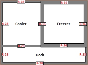
Example 10-33
Question
A 35°F cooler space is adjacent to a -10°F freezer space.
What is the minimum required insulation R-value of the shared wall between the
cooler and freezer spaces?
Answer
The minimum insulation R-value requirements should be
interpreted to apply to all surfaces enclosing the refrigerated space at the
subject temperature. Therefore, since the freezer space walls must be
insulated to the minimum R-value requirements shown in Table 10-3, the R-value
of the shared wall insulation must be at least R-36. The minimum
insulation R-value requirement of the other three cooler walls is R-28.
The figure below illustrates this example.
B.
Freezer Floor Insulation
Freezer spaces with 3,000 ft² of floor area or more shall
meet the minimum floor insulation R-value requirements shown in Table
10-3. The requirement is a minimum R-value of R-35, with an exception
if the underslab heating system increases productive refrigeration capacity, in
which case the minimum R-value is R-20.
The predominant insulating material used in freezer floors is
extruded polystyrene, which is commonly available in 2”-thick increments, but
can optionally be purchased in 1”-thick increments as well. Extruded
polystyrene has an R-value of R-5 per inch at standardized rating conditions,
and extruded polystyrene panels can be stacked, so the freezer floor can be
constructed with R-value multiples of 5 (R-30, R-35, R-40).
A lower floor insulation R-value of R-20 is allowed if all of
the underslab heat is provided by an underslab heating system that increases
productive refrigeration capacity. An example of an underslab heating
system utilizing heat from a refrigerant liquid subcooler is shown in Figure
10-27.
Figure 10-27– Underslab Heating System that Utilizes
Refrigerant Subcooling
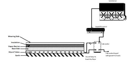
The lower R-value requirement when this type of underslab heating system
is used is justified because the increased underslab heat gain to the space due
to reduced insulation is offset by the heat extracted from the refrigerant
liquid—which is a direct reduction in compressor load. The minimum
requirement of R-20 does not mean that R-20 is the optimum or appropriate
insulation choice in all installations. Rather, R-20 is a cost-effective
trade-off when underfloor heating is obtained via productive
refrigeration. Higher insulation levels combined with heating from
productive refrigeration would further improve efficiency.
B.
Underslab Heating Controls
Underslab heating systems should be used under freezer spaces to
prevent soil freezing and expansion. The underslab heating element might
be electric resistance, forced air, or heated fluid; however, underslab heating
systems utilizing electric resistance heating elements are not permitted unless
they are thermostatically-controlled and disabled during the summer on-peak
period. The summer on-peak period is defined by the supplying electric
utility, but generally occurs from approximately 12 PM to 6 PM weekdays during
the months of May through October. The control system used to control any
electric resistance underslab heating elements must automatically turn the
elements off during this on-peak period. The control system used to
control electric resistance underslab heating elements must be shown on the building drawings,
and the control sequence demonstrating compliance with this requirement must be
documented on the drawings and in the control system specifications.
C.
Infiltration
Barriers
Passageways between freezers and higher-temperature spaces,
and passageways between coolers and non-refrigerated spaces, shall have an
infiltration barrier such as:
•
Strip curtains, or
•
An automatically closing door, or
•
Air curtain
Examples of each are shown below.
Figure 10-28 – Strip Curtains
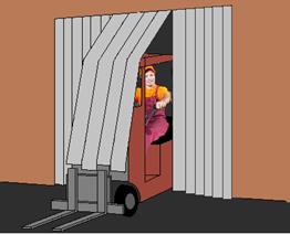
Figure 10-29 – Bi-parting automatic door
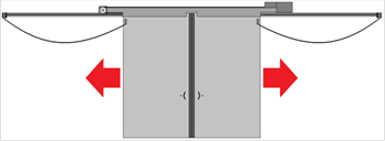
Figure 10-30 – Hinged door with spring-action door
closer and door “tight” closer
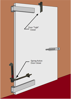
Figure 10-31 – Air Curtain
The passageways may be for, but are not limited to, people,
forklifts, pallet lifts, hand-trucks, or conveyor belts.
Strip curtains are commercial flexible plastic strips made
for refrigerated openings with material type, weight and overlap design,
designed for the size of the passageway opening and the temperatures of the
subject spaces.
An automatically closing door is a door that fully closes under
its own power. Examples include:
•
Single acting or double acting hinge-mounted doors with a spring assembly
or cam-type gravity hinges.
•
Powered single-sliding, bi-parting or rollup doors which open based on a
pull-cord, proximity or similar sensors, or by operator signal and close
automatically through similar actions or after a period of time sufficient to
allow passageway transit.
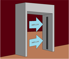
An air curtain is a commercial fan powered assembly intended
to reduce air infiltration and designed by its manufacturer for use on refrigerated warehouse passageways, and for use on the opening
size and the temperatures for which it is applied.
There are two exceptions to the requirements for infiltration
barriers:
1.
Openings with less than 16 square feet of opening area, such as small
passageways for conveyor belts
2. Loading dock
doorways for trailers
Example
10-34
Question
A refrigerated warehouse
includes a freezer, cooler, a refrigerated dock, and a conditioned office, as shown
in the following figure. Where are infiltration barriers required?
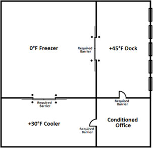
Answer
Infiltration barrier are required between all spaces
including the hinge-mounted doors between the dock and the office. The
dock doors do not require infiltration barriers.
Example 10-35
Question
A refrigerated warehouse is
being constructed for a flower distribution company. Strip curtains cannot
be used on the doors because the strips will damage the flowers when the pallet
jack passes through. Is the warehouse still required to have infiltration
barriers?
Answer
Yes, the warehouse is required
to have infiltration barriers. If strip curtains cannot be used, the
designer may choose another method, such as double-acting hinged doors, sliding
or rollup doors with automatic door closers.
D.
Acceptance Requirements
The Standards include acceptance test requirements for
electric resistance underslab heating systems in accordance with NA7.10.1.
The test requirements are described in Chapter 13 and the Reference
Nonresidential Appendix
NA7.10. The test requirements are described briefly in the following
paragraph.
E.
Electric Resistance Underslab Heating System
The acceptance requirements include functional tests that are
to be performed to verify that the electric resistance underslab heating system
automatically turns off during a test on-peak period.
10.6.3
Mechanical Systems Mandatory Requirements
A.
Overview
This section addresses mandatory requirements for mechanical
systems serving refrigerated spaces. Mechanical system components
addressed by the Standards include evaporators (air units), compressors,
condensers, and refrigeration system controls. The requirements for each
of these components are described in the following sections. The
requirements apply to all system and component types with the exception of the
specific exclusions noted in §120.6(a). The following figures identify
some of the common system and component configurations that fall under
§120.6(a).
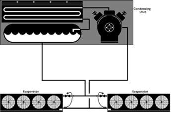
Figure
10-32 is a schematic of a single stage system with direct expansion (DX)
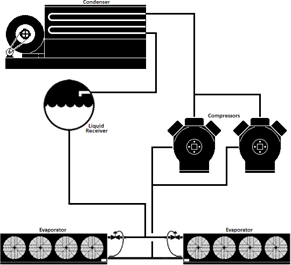
evaporator coils. Figure
10-33 identifies a single stage system with flooded evaporator coils; while
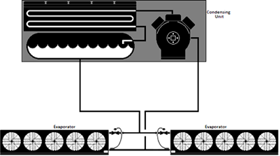
Figure
10-34 shows a single stage system with pump recirculated evaporators. Figure
10-35 is a schematic of a typical two-stage system with an intercooler
between the compressor stages. Figure
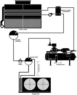
10-36 is a single-stage system with a water-cooled condenser and fluid cooler.
Figure 10-32 – Single Stage System with DX
Evaporator Coil
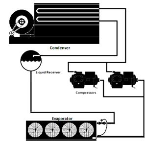
Figure 10-33– Single Stage System with Flooded Evaporator
Coil
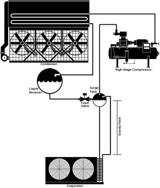
Figure 10-34 – Single Stage System with Pump
Recirculated Evaporator Coils
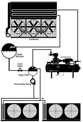
Figure 10-35 – Two-Stage System with Flooded
Evaporator Coil
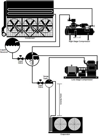
Figure 10-36 – Single System with Water-Cooled
Condenser Served by Fluid Cooler
B.
Evaporators
New fan-powered evaporators used in coolers and freezers must
meet the fan motor type, efficiency, and fan control requirements outlined in
the Standards.
a.
Allowed Fan Motor Types
Single phase fan motors less than 1 horsepower and less than
460 Volts must be either electronically-commutated (EC, also known as Brushless
DC) or must have an efficiency of 70 percent or more when rated in accordance
with NEMA Standard MG 1-2006 at full load rating conditions. This
requirement is designed to reduce fan power in small evaporator fans.
b.
Fan Motor Control
The speed of all evaporator fans served by either a suction
group with multiple compressors or by a single compressor with variable capacity
capability must be controlled in response to space temperature or humidity using
a continuously variable speed control method. Two-speed control of
evaporator fans is not an acceptable control method.
The fan speed is controlled in response to space temperature
or humidity. Fan speed should increase proportionally when the space
temperature is above setpoint and decrease when the space temperature is at or
below setpoint, with refrigerant supply and pressure being maintained in the
evaporator cooling coil. Fan speed is equivalent to air volume being
circulated, resulting in direct control of cooling capacity, analogous to “variable air
volume” cooling in commercial buildings. The control logic requires
design and tuning
to provide “variable” capacity operation.
The use of humidity as the control variable for speed control
is very limited in practice but is included in the Standards to accommodate
special strategies for humidity-sensitive perishable product. Control
logic is these applications often will employ humidity in conjunction with
temperature.
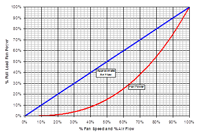
The intent of this requirement is to take advantage of the
“third-power” fan affinity law, which states that the percentage of required fan
motor power is approximately equal to the cube of the percentage of fan speed,
while the airflow is linearly proportional to the fan speed. For example,
a fan running at 80 percent speed requires approximately 51 percent
(80%3 = 51%) power while providing approximately 80 percent airflow.
(Figure 10-37) Actual power is somewhat higher due to inefficiencies and drive
losses. This shows the relationship between fan speed and both required
fan power and approximate airflow.
There is no requirement in the Standards for the minimum
speed setting (i.e. how low the fan speed must go at minimum load).
Variable speed controls of evaporator fans has commonly used minimum speeds of
80 percent or lower on direct expansion coils and 70 percent or lower on flooded
or recirculated coils. The allowable minimum fan speed setting is to be
determined by the refrigeration system designer. The fan speed may be
adjusted or controlled to maintain adequate air circulation in order to ensure
product integrity and quality.
Figure 10-37– Relationship between Fan Speed and
Required Power
Correct fan speed control requires the associated system
suction pressure to be controlled such that evaporator capacity is sufficient to
meet space loads. If the evaporator suction pressure is too high relative
to the desired room temperature, the evaporator fans will run at excessively
high speed and energy savings will not be realized. If floating suction
pressure automation is used to optimize the suction pressure setpoint, suction
pressure should only be allowed to float up after fan speeds are at minimum and
should be controlled to float back down prior to increasing fan speeds.
The Standards have three exceptions to the evaporator
variable speed requirement:
1.
In case of a replacement, addition or alteration of existing evaporators with no variable speed
control, the variable speed control of the evaporators is mandatory only if the
replacement, addition or alteration is done for all the evaporators in an
existing space. [Exception 1 to §120.6
(a) 3B]
2.
A Controlled Atmosphere (CA) storage where products that require
100 percent of the design airflow at all times are stored may be exempt from the
variable speed control requirement. A licensed engineer must certify that
the products in the cooler require continuous airflow at 100 percent speed.
Variable speed control must be implemented if the space will also be used for
non-CA product or operation. [Exception 2 to §120.6 (a) 3B]
3.
The variable speed control is not mandatory for spaces that are used solely for
quick chilling or quick freezing of products. Such spaces have design
cooling capacities that are greater than 240 Btu/hr-ft² of floor area, which is
equivalent to 2 tons per 100ft² of floor area. However, variable speed
control must be implemented if the spaces are used for storage for any length of
time, regardless of how much refrigeration capacity is installed in the space.
[Exception 3 to §120.6 (a) 3B].
Example
10-36
Question
A split system with a packaged air-cooled condensing unit
with a single 30 HP compressor with unloaders serves two direct expansion
evaporators in a 3,200 ft² cooler. Are the evaporator fans required to
have variable speed control?
Answer
Yes. Since the compressor has a variable capacity
capability in the form of unloaders, the evaporator fans are required to have
variable speed control.
Example 10-37
Question
A refrigeration system utilizes two reciprocating
compressors without variable capacity capability connected in parallel, and
serves multiple evaporators in a 10,000 ft² cooler. Are the evaporator fans
required to have variable speed control?
Answer
Yes. Since the evaporators are served by more than
one compressor, they must have variable speed control, even though the
compressors are not equipped with capacity control devices (e.g. unloaders).
In practice, the designer should consider the steps of
capacity necessary to allow stable control. For small systems, the
designer may consider use of control that proportionally controls both
compressor capacity steps and speed steps in unison. As long as this
control scheme is in response to space temperature, it would be consistent with
the Standards.
Example 10-38
Question
A -20°F (-29°C) freezer has a number of recirculated
evaporator coils that were selected to meet the design load at a 10°F (5.5°C)
temperature difference (TD). The evaporator fan motors utilize variable speed
drives and the control system varies the fan speed in response to space
temperature. What should the freezer saturated suction temperature be in
order to achieve proper control and savings – by allowing fan speed control to
act as the primary means of temperature control.
Answer
Since the coils were designed at a 10°F (5.5°C) TD and the
target freezer temperature is -20°F (-29°C), the saturated evaporating
temperature should be -30°F (-34°C) (-20°F minus 10°F); with the compressor
controlled at a lower temperature, based on the design piping pressure
drop. For example with 2°F (1°C) of piping losses, the compressor control
setpoint would be -32°F (-36°C).
The purpose of this example is to show how evaporator
temperature and coil capacity can be considered and maintained in order to
achieve proper variable speed fan operation and savings. Settings could be
further fine-tuned through observation of the required suction pressure to meet
cooling loads and achieve minimum fan speeds average load periods, yet with a
suction pressure no lower than necessary.
Example 10-39
Question
An existing refrigerated warehouse
space has eight existing evaporators that do not have variable speed
control. Six of the eight evaporators are being replaced with new
evaporators. Do the new evaporators require variable speed control?
Answer
No. Since all the evaporators are not being replaced,
the new evaporators do not require variable speed control.
The reason for this is that
effective space temperature control would often require that the entire space
utilize a consistent control scheme which could require a disproportional
cost. While not required by the Standards, in many instances it may still
be very cost effective to add variable speed control to existing as well as new
evaporators in this situation.
Continuously variable speed control is not mandatory for
evaporators that are served by a single compressor that does not have variable
capacity capability (i.e. the compressor cycles on and off in response to space
temperature). For these systems, evaporator airflow must be reduced by at
least 40 percent when the compressor is off. This can be accomplished in a
number of ways, for example:
•
Two speed evaporator fan control, with speed reduced by at least 40% when
cooling is satisfied and the compressor is off.
•
Turning off a portion of the fans in each evaporator to accomplish at
least 40% reduction in fan power. Typically baffles are required to
prevent reverse flow through fans that are turned off.
•
Turning off all fans when the compressor is off. With this strategy
a duty cycle can be employed to provide period forced fan operation to maintain
air circulation, if the “on” period is limited to 25% of the duty cycle while
the compressor is off.
Example
10-40
Question
A split system with a packaged
air-cooled condensing unit utilizing a single cycling compressor without
unloaders serves two evaporators in a cooler. Each evaporator has five
fans. What options does the system designer have to meet the requirements
for evaporator coils served by a single cycling compressor?
Answer
Multiple methods can be used to reduce airflow by at least
40% when the compressor is off, or turn all fans off with a 25% duty cycle.
Example 1: The designer may specify two-speed fans, or
utilize variable frequency drives or other speed-reduction devices to reduce the
fan speed to 60% or less when the compressor is off.
Example 2: The designer may
utilize controls that cycle at least four of the ten fans off when the
compressor is cycled off. This would most likely be accomplished by
cycling two fans off on each evaporator.
C.
Condensers
New condensers on new refrigeration systems must follow the
condenser sizing, fan control, and efficiency requirements as described in
§120.6(a)4.
Condenser Sizing
Sections §120.6(a)4A and §120.6(a)4B describe minimum sizing
requirements for new condensers serving new refrigeration systems.
Fan-powered evaporative condensers, as well as water-cooled condensers served by
fluid coolers and cooling towers are covered in Section §120.6(a)4A.
Fan-powered air-cooled condensers are covered by Section §120.6(a)4B.
Condensers must be sized to provide sufficient heat rejection
capacity under design conditions while maintaining a specified maximum
temperature difference between the refrigeration system saturated condensing
temperature (SCT) and ambient temperature. The design condenser
capacity shall be greater than the calculated combined Total Heat of Rejection
(THR) of the dedicated compressors that are served by the condenser. If
multiple condensers are specified, then the combined capacity of the installed
condensers shall be greater than the calculated heat of rejection. When
determining the design THR for the purpose of this requirement, reserve or
backup compressors may be excluded from the calculations.
There is no limitation on the type of condenser that may be
used. The choice may be made by the system designer, considering the
specific application, climate, water availability, etc.
The Standards include an exception to Sections §120.6(a)4A
and 4B for condensers serving refrigeration systems for which more than 20% of
the design cooling load comes from quick chilling or freezing space, or process (non-space)
refrigeration cooling. Title 24 defines quick chilling or freezing space
as a space with a design refrigeration evaporator capacity greater than 240
Btu/hr-ft² of floor area, which is equivalent to 2 tons per 100ft² of floor
area, at system design conditions.
The sizing requirements for air-cooled condensers (Sections
§120.6(a)4B) do not apply to the condensers included in air-cooled condensing
units. Condensing units include compressor(s), condenser, liquid receiver,
and control electronics are packaged in a single product. However, this
exception applies only if the compressor(s) in the condensing units have a
nameplate size totaling less than 100HP.
Example 10-41
Question
A new food processing facility is being constructed that
will include an 800ft² blast freezer, a holding freezer, and a loading
dock. The design evaporator capacity of the blast freezer is 40 TR (tons
of refrigeration). The combined evaporator capacity of the freezer and
loading dock is 60 TR. Does the condenser group have to comply with the
sizing requirements in §120.6(a)4A?
Answer
The blast freezer evaporator capacity divided by the floor
area is 100TR/800ft², which is equal to 12.5 TR/100ft². That means this
particular blast freezer is deemed quick freezing space by the Standards.
Therefore, the condenser group serving the refrigeration system does not have to
comply with §120.6(a)4A, since 40% (i.e. greater than 20%) of the design
refrigeration capacity is from quick freezing.
Example 10-42
Question
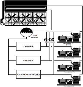
The refrigerated warehouse
system shown below has a backup or “swing” compressor. Does the heat
rejection from this compressor need to be included in the condenser sizing
calculations?
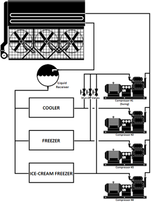
Answer
It depends.
A swing compressor may be
designed solely for back-up of multiple suction groups or it may be included in
one suction group and necessary to meet the design load of that suction group,
but in an emergency is also capable of providing back-up for other
compressors. If the compressor is solely for use as back-up, it would be
excluded from the heat rejection calculation for the purposes of the Standards.
In this case, the calculations would include the heat of rejection from
Compressors 2, 3, and 4 and would exclude Compressor 1.
Section
120.6(a)4A Sizing of Evaporative Condensers, Fluid Coolers, and Cooling
Towers
Section §120.6(a)4A provides maximum design SCT values for
evaporative condensers as well as systems consisting of a water-cooled condenser
served by a cooling tower or fluid cooler. For the purpose of this Section, designers
should use the 0.5 percent design wet-bulb temperature (WBT) from Table 10-4 –
Design Day Data for California Cities in the Reference Joint Appendices JA2 to
demonstrate compliance with this requirement. The maximum design SCT
requirements are 'listed in Table 10-4 below:Table 10-4
–Maximum Design SCT Requirements for Evaporative Condensers and Water-Cooled
Condensers Served by Cooling Towers and Fluid Coolers
|
0.5% DESIGN WET-BULB
TEMPERATURE |
MAXIMUM DESIGN
SCT |
|
≤
76°F (24°C) |
Design WBT plus 20°F
(11°C) |
|
Between 76°F (24°C) and
78°F (26°C) |
Design WBT plus 19°F
(10.5°C) |
|
≥
78°F (26°C) |
Design WBT plus 18°F
(10°C) |
Example 10-43
Question
A refrigerated
warehouse is being constructed in Fresno, California. The refrigeration
system will be served by an evaporative condenser. What is the sizing
requirement for the condenser selected for this system?
Answer
The 0.5% design
wetbulb temperature (WBT) from Joint Appendix JA-2 for Fresno,
California, is 73°F. Therefore, the maximum design SCT for the refrigerant
condenser is 73°F + 20°F = 93°F. The selected condenser for this system
must be capable of rejecting the total system design THR at 93°F SCT, and 73°F
WBT.
Example 10-44
Question
What is the minimum
size for a condenser for a refrigeration system with the following
parameters?
Located in
Fresno, California
Design SST:
10°F
Suction group: 3
equal-sized dedicated screw compressors (none are backup units)
Evaporative
condenser
200 TR (tons
refrigeration) cooling load
Answer
From the previous
example, it was determined that the design wetbulb temperature (WBT) to
demonstrate compliance for Fresno, California is 73°F and the maximum design SCT
for the evaporative condenser is 93°F (73°F + 20°F). We will assume the
system designer determined a 2°F loss between the compressors and
condenser. The designer first calculates the total heat of rejection (THR)
for the suction group at the design conditions of 10°F SST and 95°F SCT.
The selected compressors each have a rated capacity of 240 tons of refrigeration
and will absorb 300 horsepower at the design conditions. Therefore, the
calculated THR for one compressor is:
240 TR /Compressor
x 3 compressor x 12,000 Btuh/TR + 300HP x 2,545 Btuh/HP = 10,930,500
Btuh
To comply with
the Standards, a condenser (or group of condensers) must be selected that is
capable of rejecting at least 10,930,500 Btu/hr at 93°F SCT and 73°F
WBT.
Section
120.6(a)4B Sizing of Air-Cooled Condensers
Section
120.6(a)4B provides maximum design SCT values for air-cooled
condensers. For the purpose of this Section, Designers should use the 0.5
percent design dry-bulb temperature (DBT) from Table 10-4– Design Day Data for
California Cities in the Reference Joint Appendices JA2 to
demonstrate compliance with this requirement.
Standard practice is for published condenser ratings to
assume the capacity of air-cooled condensers is proportional to the temperature
difference (TD) between SCT and DBT, regardless of the actual ambient
temperature entering the condenser. For example, the capacity of an
air-cooled condenser operating at an SCT of 80°F with a DBT of 70°F is assumed
to be equal to the same unit operating at 110°F SCT and 100°F DBT, since the TD
across the condenser is 10°F in both examples. Thus, unlike evaporative
condensers, the requirement for air-cooled condensers does not have varying
sizing requirements for different design ambient temperatures.
However, the Standards have different requirements for
air-cooled condensers depending on the space temperatures served by the
refrigeration system. The maximum design SCT requirements are 'listed in
Table 10-5 below:.
Table 10-5 – Maximum Design SCT Requirements for
Air-Cooled Condensers
Often, a single refrigeration system and its associated
condenser will serve a mix of cooler and freezer spaces. In this instance,
the maximum design SCT shall be a weighted average of the requirements for
cooler and freezer spaces, based on the design evaporator capacity of the spaces
served.
Example
10-45
Question
An air-cooled condenser is
being sized for a system that has half of its installed capacity serving cooler
space and the other half serving freezer space. What is the design TD to
be added to the design dry bulb temperature?
Answer
Using air-cooled condensers for coolers have a design
approach of 15°F (8.3°C) and for freezers a design approach of 10°F
(5.6°C). When a system serves freezer and cooler spaces, a weighted
average should be used based on the installed capacity. To calculate the
weighted average, multiply the percent of the total installed capacity dedicated
to coolers by 15°F (8.3°C). Next, multiply the percent of the total
installed capacity dedicated to freezers by 10°F (5.6°C). The sum of the
two results is the design condensing temperature
approach. In this example, the installed capacity is evenly split between
freezer and cooler space. As a result, the design approach for the
air-cooled condenser is 12.5°F (6.9°C).
(50% x 15 oF) +
(50% x 10oF) = 7.5 oF + 5 oF = 12.5
oF
Fan Control
Condenser fans for new air-cooled or evaporative condensers,
or fans on cooling towers or fluid coolers used to reject heat on new
refrigeration systems, must be continuously variable speed. Variable
frequency drives are commonly used to provide continuously variable speed
control of condenser fans although controllers designed to vary the speed of
electronically commutated motors may be used to control these types of
motors. All fans serving a common high side, or cooling water loop for
cooling towers and fluid coolers, shall be controlled in unison. Thus, in
normal operation, the fan speed of all fans within a single condenser or set of
condensers serving a common high-side should modulate together, rather than
running fans at different speeds or staging fans off. However, when fan
speed is at the minimum practical level usually no higher than 10-20%, the fans
may be staged off to further reduce condenser capacity. As load increases,
fans should be turned back on prior to significantly increasing fan speed,
recognizing a control band is necessary to avoid excessive fan cycling.
To minimize overall system energy consumption, the condensing
temperature setpoint must be continuously reset in response to ambient
temperatures, rather than using a fixed setpoint value. This strategy is
also termed ambient-following control, ambient-reset, wetbulb following and
drybulb following—all referring to control logic which changes the condensing
temperature target in response to ambient conditions at the condenser. The
control system calculates a target saturated condensing temperature that is
higher than the ambient temperature by a predetermined temperature difference
(i.e. the condenser control TD). Fan speed is then modulated according to
the calculated target SCT. The target SCT for evaporative condensers or
water-cooled condensers (via cooling towers or fluid coolers) must be reset
according to ambient wet bulb temperature, and the target SCT for air-cooled
condensers must be reset according to ambient dry bulb temperature.
The condenser control TD is not specified in the
Standards. The nominal control value is often less than the condenser
design TD; however the value for a particular system is left up to the system
designer. Since the intent is to utilize as much condenser capacity as
possible without excessive fan power, common practice for refrigerated warehouse
systems is to optimize the control TD over a period of time such that the fan
speed is in a range of approximately 60-80% during normal operation (i.e. when
not at minimum SCT). While not required, evaporative condensers and
systems utilizing fluid coolers and cooling towers may also vary the condenser
control TD as a function of actual WBT, to account for the properties of moist
air, which reduce the effective condenser capacity at lower wetbulb
temperatures.
The minimum saturated condensing temperature setpoint must be
70°F (21°C) or less. For systems utilizing halocarbon refrigerants with
glide, the SCT setpoint shall correlate with a midpoint temperature (between the
refrigerant bubble-point and dew point temperatures) of 70°F (21°C) or
less. As a practical matter, a maximum SCT setpoint is also commonly
employed to set an upper bound on the control setpoint in the event of a sensor
failure and to force full condenser operation during peak ambient
conditions. This value should be set high enough that it does not
interfere with normal operation.
Split air-cooled condensers are sometimes used for separate
refrigeration systems, with two circuits and two rows of condenser fans.
Each condenser half would be controlled as a separate condenser. If a
condenser has multiple circuits served by a common fan or set of fans, the
control strategy may utilize the average condensing temperature or the highest
condensing temperature of the individual circuits as the control variable for
controlling fan speed.
Alternative control strategies are permitted to the
condensing temperature reset control required in Section
§120.6(a)4E. The alternative control strategy must be demonstrated to
provide equal or better performance, as approved by the Executive Director.
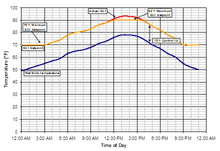
Example 10-46
Question
A refrigerated warehouse with evaporative condensers is
being commissioned. The control system designer has utilized a wet
bulb-following control strategy to reset the system saturated condensing
temperature (SCT) setpoint. The refrigeration engineer has calculated that
adding a TD of 15°F (8.3°C) above the ambient wet bulb temperature should
provide a saturated condensing temperature setpoint that minimizes the combined
compressor and condenser fan power usage throughout the year. What might
the system SCT and SCT setpoint trends look like over an example day?
Answer
The following figure illustrates what the actual saturated
condensing temperature and SCT setpoints could be over an example day using the
wet bulb-following control strategy with a 15°F (8.3°C) TD and also observing
the 70°F (21°C) minimum condensing temperature requirement. As the figure
shows, the SCT setpoint is continuously reset to 15°F (8.3°C) above the ambient
wet bulb temperature until the minimum SCT setpoint of 70°F is reached. The
figure also shows a maximum SCT setpoint (in this example, 90°F (32.2°C) which
may be utilized to limit the maximum control setpoint, regardless of the ambient
temperature value or TD parameter.
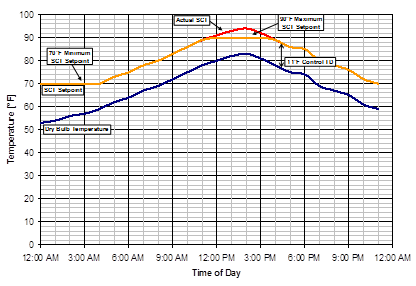
Example 10-47
Question
A cold storage facility with an air-cooled condenser is
being commissioned. The control system designer has utilized a
drybulb-following control strategy to reset the system saturated condensing
temperature (SCT) setpoint. The refrigeration engineer has calculated that
adding a TD of 11°F (6.1°C) above the ambient drybulb temperature should provide
a saturated condensing temperature setpoint that minimizes the combined
compressor and condenser fan power usage throughout the year. What might
the system SCT and SCT setpoint trends look like over an example day?
Answer
The following figure illustrates the actual saturated
condensing temperature and SCT setpoints over an example day using the
drybulb-following control strategy with an 11°F (6.1°C) TD and also observing
the 70°F (21°C) minimum condensing temperature requirement. As the figure
shows, the SCT setpoint is continuously reset 11°F (6.1°C) above the ambient
drybulb temperature, but is bounded by the minimum and maximum SCT
setpoints. The figure also shows a maximum SCT setpoint (in this example,
90°F (32.2°C) which may be utilized to limit the maximum control setpoint,
regardless of the ambient temperature value or TD parameter.
Section
120.6(a)4F Condenser Specific
Efficiency
Requirements for Design Condensing Temperatures relative to
design ambient temperatures, as described above for §120.6(a)4A&B, help
assure that there is enough condenser capacity to keeping condensing
temperatures compressor head pressures at reasonable levels. However the
sizing requirements do not address condenser efficiency. For example,
rather than providing amply sized condenser surface area, a condenser selection
could consist of a small condenser area using a large motor to blow a large
amount of air through the heat exchanger surface to achieve the design condenser
TD. However, this would come at the expense of excessive fan motor
horsepower. Also, relatively high fan power consumption can result from
using condenser fans that have poor fan efficiency or low fan motor
efficiency. Section 120.6(a)4F addresses these and other factors affecting
condenser fan power by setting minimum specific efficiency requirements for
condensers.
All newly installed indoor and outdoor evaporative
condensers, and outdoor air-cooled condensers to be installed on new
refrigeration systems shall meet the minimum specific efficiency requirements
shown in Table 10-6.
Table 10-6 – Fan-powered Condensers – Minimum Specific
Efficiency Requirements
|
CONDENSER TYPE |
REFRIGERANT TYPE |
MINIMUM SPECIFIC EFFICIENCY |
RATING CONDITION |
|
Outdoor Evaporative-Cooled with THR Capacity >
8,000 MBH |
All |
350 Btuh/Watt |
100°F Saturated Condensing
Temperature (SCT), 70°F Outdoor Wetbulb Temperature |
|
Outdoor Evaporative-Cooled with THR Capacity <
8,000 MBH and Indoor Evaporative-Cooled |
All |
160 Btuh/Watt |
|
Outdoor
Air-Cooled |
Ammonia |
75 Btuh/Watt |
105°F Saturated Condensing Temperature (SCT), 95°F
Outdoor Drybulb Temperature |
|
Halocarbon |
65 Btuh/Watt |
|
Indoor Air-Cooled |
All |
Exempt |
Condenser specific
efficiency is defined as:
Condenser Specific Efficiency = Total Heat Rejection (THR)
Capacity / Input Power
The total heat rejection capacity is at the rating conditions
of 100°F Saturated Condensing Temperature (SCT) and 70°F outdoor wetbulb
temperature for evaporative condensers, and 105°F SCT and 95°F outdoor drybulb
temperature for air-cooled condensers. Input power is the electric input
power draw of the condenser fan motors (at full speed), plus the electric input
power of the spray pumps for evaporative condensers. The motor power is
the manufacturer’s published applied power for the subject equipment, which is
not necessarily equal to the motor nameplate rating. Power input for
secondary devices such as sump heaters shall not be included in the specific
efficiency calculation.
As shown in Table 10-6 the Standards have different minimum
efficiencies depending on the type of condenser that is being used. The
different classifications of condenser are:
•
Outdoor, evaporative, THR greater than 8,000 MBH at specific efficiency
rating conditions
•
Outdoor, evaporative, THR less than 8,000 MBH at specific efficiency
rating conditions
•
Indoor, evaporatively cooled
•
Outdoor, air-cooled, ammonia refrigerant
•
Outdoor, air-cooled, halocarbon refrigerant
•
Indoor, air-cooled
The data published in the condenser manufacturer’s published
rating for capacity and power shall be used to calculate specific
efficiency. For evaporative condensers, manufacturers typically provide
nominal condenser capacity, and tables of correction factors that are used to
convert the nominal condenser capacity to the capacity at various applied
condensing temperatures and wetbulb temperatures. Usually the manufacturer
publishes two sets of correction factors: one is a set of “heat rejection”
capacity factors, while the others are “evaporator ton” capacity factors.
Only the “heat rejection” capacity factors shall be used to calculate the
condenser capacity at the efficiency rating conditions for the purpose of
determining compliance with this section.
For air-cooled condensers, manufacturers typically provide
the capacity at a given temperature difference (TD) between SCT and drybulb
temperature. Manufacturers typically assume that air-cooled condenser
capacity is linearly proportional to TD; the catalog capacity at 20°F TD is
typically twice as much as at 10°F TD. The condenser capacity for
air-cooled condensers at a TD of 10°F shall be used to calculate
efficiency. If the capacity at 10°F TD is not provided, the capacity shall
be scaled linearly.
Depending on the type of condenser, the actual manufacturer’s
rated motor power may vary from motor nameplate in different ways. Air
cooled condensers with direct-drive OEM motors may use far greater input power
than the nominal motor horsepower would indicate. On the other hand,
evaporative condenser fans may have a degree of safety factor to allow for
higher motor load in cold weather conditions (vs. the 100°F SCT/70°F WBT
specific efficiency rating conditions). Thus, actual motor input power
from the manufacturer must be used for direct-drive air-cooled condensers while
for large (i.e. > 8,000 MBH) evaporative condensers and other belt drive
condensers, the full load motor rating is generally conservative but
manufacturer’s applied power should be used whenever possible to more accurately
determine specific efficiency.
Example 10-48
Question
An evaporative condenser is being considered for use in an
outdoor application on a new refrigerated
warehouse. The refrigerant is ammonia. The condenser
manufacturer’s catalog provides the following information:
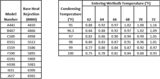
For this example, model number D551 is being
considered. Elsewhere in the catalog, it states that condenser model D551
has two 7.5 HP fan motors and one 5 HP pump motor. Fan motor efficiencies
and motor loading factors are not provided. Does this condenser meet the
minimum efficiency requirements?
Answer
First, the condenser capacity must be calculated at the
efficiency rating condition. From Table 10-4, we see that the rating conditions
for an outdoor evaporative condenser are 100°F SCT, 70°F WBT. From the
Base Heat Rejection table above, we see the nominal capacity for model D551 is
5,513 MBH. From the Heat Rejection Capacity Factors table, we see that the
correction factor for 100°F SCT, 70°F WBT is 0.88. The capacity of this
model at specific efficiency rating conditions is 5,513 MBH / 0.88 = 6,264
MBH. Since 6,264 MBH is less than 8,000 MBH, we can see from Table10-4that
the minimum specific efficiency requirement is 160 (Btu/hr)/Watt.
To calculate input power, we will assume 100% fan and pump
motor loading and minimum motor efficiency since the manufacturer has not yet
published actual motor input power at the specific efficiency rating
conditions. We look up the minimum motor efficiency from Nonresidential Appendix NA3:
Fan Motor Efficiencies. For a 7.5 HP 4-pole open fan motor, the minimum
efficiency is 91.0%. For a 5 HP 6-pole open pump motor, the minimum
efficiency is 89.5%. The fan motor input power is calculated to be:
2 Motors x 7.5 HP/Motor x 746 Watts/HP x 100% assumed
loading/ 91% Efficiency = 12.297 Watts
The pump
motor input power is calculated to be:
1 Motors x 5 HP/Motor x 746 Watts/HP x 100% assumed
loading/ 89.5% Efficiency = 4.168 Watts
The combined input power is therefore:
12.297 Watts + 4.168 Watts = 16.464 Watts
Note: Actual motor power should be used when available (see
notes in text).
Finally, the efficiency of the condenser is:
(6,264 MBH x 1000 Btuh/MBH) / 16.464 Watts = 381
Btuh/Watt
381 Btu/hr per Watt is higher
than the 160 Btu/hr per Watt requirement. This condenser meets the minimum
efficiency requirements.
Condenser Fin Spacing
According to Section
120.6(a)4G air-cooled condensers shall have a fin density no greater than 10
fins per inch. Condensers with higher fin densities have a higher risk of
fouling with airborne debris. This requirement does not apply to
air-cooled condensers that utilize a micro-channel heat exchange surface, since
this type of surface is not as susceptible to permanent fouling in the same
manner as traditional tube-and-fin condensers with dense fin spacing.
D.
Compressors
Compressors on new refrigeration systems must follow the
design and control requirements as described in §120.6(a)5.
Minimum Condensing Temperature
Floating head control is one of the largest energy savings
measures applied to refrigeration systems. This control attempts to keep
condensing temperatures as low as possible (while not consuming too much
condenser fan energy) as this reduces compressor head pressure which directly
impact compressor energy. When ambient temperatures are low the primary
constraint on how low the condensing temperature can be reset is the design
requirements of the compressor and associated system components.
Section
120.6 (a)5A addresses the compatibility of the compressor design and
components with the requirements for floating head control. All
compressors that discharge to the condenser(s) and all associated components
(coalescing oil separators, expansion valves for liquid injection oil cooling,
etc.) must be capable of operating at a condensing temperature of 70°F (21°C) or
less. Note that oil separator sizing is often governed by the minimum
condensing temperature as well as other factors, such as the maximum suction
temperature. Suction temperatures above the design value may occur under
floating suction temperature control schemes.
The system designer should also keep in mind that other
design parameters such as piping run-lengths or evaporator defrost requirements
must be considered to meet this requirement.
Screw Compressor Control at Part-Load
New open-drive screw compressors in new refrigeration systems
with a design saturated suction temperature (SST) of 28°F or lower shall vary
compressor speed as the primary means of capacity control. The compressor
speed shall reduce to the manufacturer-specified minimum speed before unloading
via slide valve. Similarly, when the load increases, the compressor shall
increase to 100% slide valve before increasing speed. This requirement
applies only to compressors discharging to the condenser (i.e. single stage or
the high stage of a two-stage system) and only to suction groups that consist of
a single compressor.
An exception to §120.6(a)5
is provided for compressors on a refrigeration system with more than 20% of the
design cooling load from quick chilling or freezing space, or non-space process refrigeration
cooling. The “refrigeration system” refers to the entire associated
system, (i.e. the refrigerant charge) not the suction group. While
variable speed compressor control may be cost effective in many instances and
may be considered by the system designer, this exception exists to allow for
situations such as seasonal processes with low operating hours or loads that may
be precisely matched to a fully loaded compressor.
New screw compressors with a motor nameplate power greater
than 150HP shall incorporate the capability to automatically vary the volume
ratio (i.e. variable Vi) in order to optimize efficiency at off-design operating
conditions.
Example
10-49
Question
The system shown below has three 200 HP open-drive screw
compressors serving three different suction levels and one 200 HP backup or
swing open-drive screw compressor that can be connected by valve into any of the
three suction lines. Does this count as having more than one compressor
per suction group and exempt the compressors from the requirements in
§120.6(a)5B?
Answer
Probably not. The Exception 1 to §120.6(a)5B
only applies when a suction group has two or more dedicated compressors. A
compressor that is used solely as backup does not count as a dedicated
compressor. As a result, all compressors (1, 2, 3, and 4) in the example
above must comply with §120.6(a)5B and use variable speed control as the primary
means of capacity control.
However, if Compressor 1 is actually required to meet the
design load of one of the suction groups, it could be considered part of that
suction group and variable speed control would not be required. Whether a
swing compressor is really a back-up compressor or part of a suction group
should be apparent from the design loads and capacities 'listed in
the design documents.
E.
Acceptance Requirements
The Standards have acceptance test requirements for:
1.
Electric underslab heating controls
2.
Evaporator fan motor controls
3.
Evaporative condensers
4.
Air-cooled condensers
5.
Variable speed compressors
These test requirements are described in Chapter 13 and the Reference
Nonresidential Appendix
NA7.10. They are described briefly in the following paragraphs.
Electric Underslab
Heating Controls
Controls for underslab electric heating controls, when used
for freeze protection on freezer floors, are tested to ensure heat is automatically
turned off during summer on-peak electric periods.
Evaporator Fan Motor
Controls
Evaporator equipment and controls are checked for proper
operation. The controls are tested to ensure the fan speed automatically varies
in response the temperature and/or humidity of the space.
Evaporative
Condensers
Evaporative condensers and variable speed fan controls are
checked to ensure the required minimum SCT setpoint of 70°F or lower is
implemented, and the condenser fans continuously vary in unison to maintain a
target temperature difference between the SCT and the wet bulb temperature.
Trends of wet bulb temperature and SCT can be used to verify the controls over
time.
The condenser control TD or offset is a key parameter in
fine-tuning the
operation of the fans and maximizing the energy savings. In best practice,
this control setting should be adjusted during average loaded so that the fan
average 60-80% speed when in the control range (i.e. between the minimum and
maximum SCT setpoints).
Air-cooled
Condensers
Air-cooled condensers and variable speed fan controls are
checked to ensure the required minimum SCT setpoint of 70°F or lower is
implemented, and the condenser fans continuously vary in unison to maintain a
target temperature difference between the SCT and dry bulb temperature.
Trends of dry bulb temperature and SCT can be used to verify the controls over
time.
The condenser control TD is a key parameter in fine-tuning
the operation of the fans and maximizing the energy savings. This control
setting should be adjusted during average loaded so that condenser capacity is
effectively utilized but fan speed is not excessive.
Variable Speed Compressors
The controls and equipment for the variable speed control of
screw compressors is checked and certified as part of the acceptance
requirements. The compressor should unload capacity by reducing speed to
the minimum speed setpoint before unloading by slide valve or other means.
Control system trend screens can also be used to verify that the speed varies
automatically in response to the load.
10.6.4
Additions and Alterations
A.
Requirements
Requirements related to refrigerated warehouse
additions and alterations are covered by the Standards in §141.1(a).
The specific requirements for additions and alterations for commercial
refrigeration are included in 120.6(a).
Definitions relevant to refrigerated warehouses include:
•
An addition is a change to an existing refrigerated warehouse that
increases refrigerated floor area and volume. Additions are treated like
new construction.
•
When an unconditioned or conditioned building; or unconditioned or
conditioned part of a building adds refrigeration equipment so that it becomes
refrigerated, this area is treated as an addition.
•
An alteration is a change to an existing building that is not an
addition or repair.
An alteration could include installing new evaporators, a new lighting system,
or a change to the building envelope, such as adding insulation.
•
A repair is the reconstruction or renewal of any part of an existing
building or equipment for the purpose of its maintenance. For example, a repair
could include the replacement of an existing evaporator or condenser.
Any addition or altered space must meet all applicable
mandatory requirements. Repairs must not increase the preexisting energy
consumption of the repaired component, system, or equipment; otherwise, it is
considered to be an alteration.
Example
10-50
Question
The new construction is an
addition to an existing refrigerated warehouse. The new space is served by an
existing refrigeration plant. Does the refrigeration plant need to be updated to
meet the Standards?
Answer
No. The new construction must comply with the Standards;
however, the existing refrigeration plant equipment is exempt from the
Standards.
Example 10-51
Question
The new construction includes an addition to refrigerated
space and expansion of the existing refrigeration plant. Is the existing
refrigeration equipment subject to the Standards requirements?
Answer
No. Only the new equipment installed in the added
refrigerated space and any new compressors added to the existing plant are
subject to the requirements of the Standards. If a new refrigeration system was
installed with a new condenser for the addition then the new condenser must also
comply with the Standards.
Example 10-52
Question
An upgrade to an existing refrigerated storage space
includes replacing all of the existing evaporators with new evaporators. Do the
new evaporators need to comply with the Standards?
Answer
Yes. A complete renovation of the evaporators in the space
is considered to be an alteration. The alteration requirements apply when all of
the evaporators in the space are changed.
Example 10-53
Question
An existing refrigerated storage space is adding additional
evaporators to meet an increase in the refrigeration load. Do the new
evaporators need to comply with the Standards?
Answer
No. The alteration requirements apply only when all of the
evaporators in the space are changed.
Example 10-54
Question
An existing evaporator is being replaced by a new
evaporator as part of system maintenance. Does the new evaporator need to comply
with the Standards?
Answer
No. Replacement of an evaporator
during system maintenance is considered a repair. However, the energy
consumption of the new evaporator must not exceed that of the equipment it
replaced.
10.6.5
Compliance Documentation (NRCC-PRC-06-E through NRCC-PRC-08-E) for Refrigerated
Warehouses
At the time a building permit application is
submitted to the enforcement agency, the applicant also submits plans and energy
compliance documentation. This section describes the forms and recommended
procedures documenting compliance with the requirements of the Standards for
refrigerated warehouses. The following discussion is addressed to the designer
preparing construction documents and compliance documentation, and to the
enforcement agency plan checkers who are examining those documents for
compliance with the Standards.
A.
NRCC-PRC-06-E for Refrigerated Warehouses: Certificate of Compliance
NRCC-PRC-06-E is the primary form for Refrigerated
Warehouses, which provides compliance information for the use of the enforcement
agency’s field inspectors. This form must be included on the plans,
usually near the front of the assembly drawings. A copy of these forms should
also be submitted to the enforcement agency along with the rest of the
compliance submittal at the time of building permit application. With
enforcement agency approval, the applicant may use alternative formats of these
forms (rather than the Energy Commission’s forms), provided the information is
the same and in similar format.
Project Description
PROJECT NAME is the title of the project, as shown on the
plans and known to the enforcement agency.
CLIMATE ZONE is the California Climate zone in which the
project is located. See Reference Joint Appendix JA2 for a listing
of climate
zones.
CONDITIONED FLOOR AREA has a specific meaning under the
Standards. The number entered here should match the floor area entered on
the other forms.
PROJECT ADDRESS is the address of the project as shown on the
plans and known to the enforcement agency.
DATE is the last revision date of the plans. If the
plans are revised after this date, it may be necessary to re-submit the
compliance documentation to reflect the altered design. Note that it is
the enforcement agency’s discretion whether or not to require new compliance
documentation.
General Information
PHASE OF CONSTRUCTION indicates the status of the building
project described in the compliance documents. Refer to Section 1.7 for detailed
discussion of the various choices.
NEW CONSTRUCTION should be checked for all new buildings, newly
conditioned space or for new construction in existing buildings (tenant
improvements, see Section
1.7.11, 1.7.12)
that are submitted for envelope compliance.
ADDITION should be checked for an addition which is not treated
as a stand-alone building, but which uses option 2 described in Section
1.7.14. Tenant improvements that increase conditioned floor area and
volume are additions.
ALTERATION should be checked for alterations to an existing
building mechanical systems (see Section
1.7.13). Tenant improvements are usually alterations.
Documentation Author’s Declaration Statement
The CERTIFICATE of COMPLIANCE is signed by both the Documentation Author and the Principal Refrigerated Warehouse
Designer who is responsible for preparation of the plans of building. This
latter person is also responsible for the energy compliance documentation, even
if the actual work is delegated to a different person acting as Documentation
Author. It is necessary that the compliance documentation be consistent
with the plans.
DOCUMENTATION AUTHOR is the person who prepared the energy
compliance documentation and who signs the Declaration Statement. The
person’s telephone number is given to facilitate response to any questions that
arise. A Documentation Author may have additional certifications such as
an Energy Analyst or a Certified Energy Plans Examiner certification
number. Enter number in the EA# or CEPE# box.
Principal Refrigerated Warehouse
Designer’s Declaration Statement
The Declaration Statement is signed by the person responsible
for preparation of the plans for the building. This principal designer is
also responsible for the energy compliance documentation, even if the actual
work is delegated to someone else (the Documentation Author as described
above). It is necessary that the compliance documentation be consistent
with the plans. The Business and Professions Code governs who is qualified
to prepare plans and therefore to sign this statement. See Section
2.2.2 Permit Application for applicable text from the Business and
Professions Code.
Mandatory Measures Note Block
The person with overall responsibility must ensure that the
Mandatory Measures that apply to the project are 'listed on
the plans. The format of the list is left to the discretion of the
Principal Refrigerated Warehouse Designer.
|
Insulation Requirements (§120.6(a)1) |
|
□ Exterior surfaces shall
be insulated at least to the R-values of Table
120.6-A |
|
Underslab Heating
(§120.6(a)2) |
|
□ Electric
resistance heat shall not be used for the purposes of underslab
heating. |
|
Evaporators
(§120.6(a)3) |
|
□ Single phase fan
motors less than 1 hp and less than 460 Volts in newly installed
evaporators shall be electronically commutated motors or shall have a
minimum motor efficiency of 70 percent when rated in accordance with NEMA
Standard MG 1-2006 at full load rating conditions. |
|
□ Evaporator fans
served either by a suction group with multiple compressors, or by a single
compressor with variable capacity capability shall be variable speed and
the speed shall be controlled in response to space temperature or
humidity. |
|
□ Evaporator fans
served by a single compressor that does not have variable capacity shall
utilize controls to reduce airflow by at least 40 percent for at least 75
percent of the time when the compressor is not running. |
|
Condensers
(§120.6(a)4) |
|
□ Design saturated
condensing temperature for evaporative-cooled condensers
and water-cooled condensers served by fluid coolers or cooling towers
shall be less than or equal to:
§ Design wb +20oF in
locations where the design wb temperature is ≤ 76oF or
§ Design wb +19oF in
locations where the design wb temperature is between 76oF and
78oF or
§ Design wb +18oF in
locations where the design wb temperature is ≥ 78oF
or |
|
□ The increase in
hydrofluorocarbon (HFC) refrigerant charge associated with refrigeration
heat recovery equipment and piping shall be no greater than 0.35 lbs. per
1,000 Btu/h of heat recovery heating capacity. |
|
□ Design saturated
condensing temperatures for air-cooled condensers shall be less than or
equal to the design db temperature +10oF for systems serving
freezers and shall be ≤ the design db temperature +15oF for
systems serving coolers. |
|
□ All condenser fans
for evaporative-cooled condensers or fans on cooling towers or fluid
coolers shall be continuously variable speed and the condensing
temperature control system shall control the speed of all fans serving a
common condenser high side in unison. The minimum condensing
temperature setpoint shall be ≤ 70oF. |
|
□ All condenser fans
for air-cooled condensers shall be continuously variable speed and the
condensing temperature or pressure control system shall control the speed
of all condenser fans serving a common condenser high side in
unison. The minimum condensing temperature setpoint shall be ≤
70oF. |
|
□ Condensing
temperature reset. The condensing temperature setpoint of systems
served by air-cooled condensers shall be reset in response to ambient db
temperature. The condensing temperature setpoint of systems served
by evaporative-cooled condensers or water-cooled condensers shall be reset
in response to ambient wb temperatures. |
|
□ Fan-powered
condensers shall meet the condenser efficiency requirements 'listed in Table
120.6-B |
|
□ Air-cooled
condensers shall have a fin density no greater than 10 fins per
inch. |
|
Compressors
(§120.6(a)5) |
|
□ Compressors shall
be designed to operate at a minimum condensing temperature of
70oF or less. |
|
□ Open-drive screw
compressors in new refrigeration systems with a design saturated suction
temperature (SST) of 28oF or lower that discharges to the
system condenser pressure shall control compressor speed in response to
the refrigeration load. |
|
□ Screw compressors
with nominal electric motor power greater than 150 HP shall include the
ability to automatically vary the compressor volume ratio (Vi) in response
to operating pressures. |
|
Infiltration
Barriers (§120.6(a)6) |
|
□ Passageways
between freezers and higher-temperature spaces, and passageways between
coolers and non-refrigerated spaces, shall have an infiltration barrier
consisting of strip curtains, an automatically-closing door, or an air curtain designed by
the manufacturer for use in the passageway and temperature for which it is
applied. |
|
Refrigeration System Acceptance
(§120.6(a)7) |
|
□ Electric
resistance underslab heating systems shall be tested in accordance with NA
7.10.1. |
|
□ Evaporator fan
motor controls shall be tested in accordance with NA
7.10.2. |
|
□ Evaporative
condensers shall be tested in accordance with NA
7.10.3.1. |
|
□ Air-cooled
condensers shall be tested in accordance with NA
7.10.3.2. |
|
□ Variable speed
compressors shall be tested in accordance with NA
7.10.4. |
Refrigerated Warehouse Compliance Forms and Worksheets
Block
Principle Refrigerated Warehouse Designer should indicate the
compliance forms and worksheets that are applicable to the project.
Required Acceptance Tests
This form is new to the set of compliance forms for
Refrigerated Warehouses.
PROJECT NAME is the title of the project, as shown on the
plans and known to the enforcement agency.
DATE is the last revision date of the plans. If the
plans are revised after this date, it may be necessary to re-submit the
compliance documentation to reflect the altered design. Note that it is
the enforcement agency‘s discretion whether or not to require new compliance
documentation.
The form includes a fill-in-the-blank table to indicate which
acceptance tests apply to the project. Acceptance tests for Refrigerated
Warehouses are described in Nonresidential Appendix
NA7 and are 'listed in Table 10-7 below.
Table10-7 - Acceptance Tests for Refrigerated
Warehouses
|
Test per Section NA7 |
Applicable Equipment or System |
|
NA7.10.1 |
Electric resistance underslab heating
system |
|
NA7.10.2 |
Evaporator fan motor controls |
|
NA7.10.3.1 |
Evaporative condensers |
|
NA7.10.3.2 |
Air-cooled condensers |
|
NA7.10.4 |
Variable speed
compressors |
The Principle Refrigerated Warehouse
Designer should list the equipment and systems that require acceptance tests and
check the boxes next to the acceptance tests that apply to the respective
equipment and systems. The Enforcement Agency should
not accept the form unless the correct boxes are checked and/or filled in and
the form is signed by the persons performing the tests.
NRCC-PRC-06-E for Refrigerated Warehouses: Condenser Specific Efficiency
Worksheet
Page 1 of 3
Evaporative Condensers
This page includes the specific efficiency calculations for
evaporative condensers. Fluid coolers are exempt from the specific
efficiency requirements.
TAG/ID indicates the identification name of the condenser
that matches the building plans.
FANS – MOTOR POWER (HP) indicates the fan motor power in HP
on the name plate of the fan motor.
FANS – MOTOR EFFICIENCY indicates the fan motor efficiency on
the name plate of the fan motor.
FANS – MOTOR POWER INPUT (KW) indicates the fan motor input
power in kW calculated by using FANS – MOTOR POWER (HP) and FANS – MOTOR
EFFICIENCY.
FANS – TOTAL FAN POWER (KW) indicates the sum of the fan
motor power inputs of all fans of the condenser in kW.
PUMPS – MOTOR POWER (HP) indicates the pump motor power in HP
on the name plate of the pump motor.
PUMPS – MOTOR EFFICIENCY indicates the pump motor efficiency
on the name plate of the pump motor.
PUMPS – MOTOR POWER INPUT (KW) indicates the pump motor input
power in kW calculated by using PUMPS – MOTOR POWER (HP) and PUMPS – MOTOR
EFFICIENCY.
PUMPS – TOTAL FAN POWER (KW) indicates the sum of the total
pump motor input powers of all pumps of the condenser in kW.
CONDENSER - CAPACITY (MBH) indicates the condenser heat
rejection capacity from the manufacturer’s catalog at 100ºF saturated condensing
temperature and 70ºF ambient wetbulb temperature.
CONDENSER - TOTAL INPUT POWER (KW) indicates the sum of the
input powers of all fans and pumps of the condenser in kW.
CONDENSER – SPECIFIC EFFICIENCY (BTUH/WATT) indicates the
specific efficiency of the condenser calculated from CONDENSER - CAPACITY (MBH)
and CONDENSER - TOTAL INPUT POWER (KW).
Page 2 of 3
Air-cooled condensers
This page includes the specific efficiency calculations for
air-cooled condensers.
TAG/ID indicates the identification name of the condenser
that matches the building plans.
NUMBER OF FANS indicates the number of fans on the
condenser.
MOTOR POWER (HP) indicates the fan motor power in HP on the
name plate of the fan motor.
MOTOR EFFICIENCY indicates the fan motor efficiency on the
name plate of the fan motor.
TOTAL INPUT POWER (KW) indicates the sum of the input powers
of all fans of the condenser in kW. It is calculated by using NUMBER OF
FANS, MOTOR POWER (HP) and MOTOR EFFICIENCY.
CONDENSER - CAPACITY (MBH) indicates the condenser heat
rejection capacity from the manufacturer’s catalog at 105ºF saturated condensing
temperature and 95ºF ambient drybulb temperature (10ºF TD).
CONDENSER – SPECIFIC EFFICIENCY (BTUH/WATT) indicates the
specific efficiency of the condenser calculated from CONDENSER - CAPACITY (MBH)
and TOTAL INPUT POWER (KW).
NRCC-PRC-07-E for Refrigerated Warehouses: Refrigerated
Warehouse Space
Requirements
Page 1 of 3
Page 1 of 3 includes Insulation Details.
PROJECT NAME is the title of the project, as shown on the
plans and known to the enforcement agency.
DATE is the last revision date of the plans. If the
plans are revised after this date, it may be necessary to re-submit the
compliance documentation to reflect the altered design. Note that it is
the enforcement agency‘s discretion whether or not to require new compliance
documentation.
BUILDING TYPE indicates the area of the warehouse. If
the Refrigerated Warehouse space is less than 3,000 square feet then does not
have to comply with the space requirements of the Standards. However, it
must meet the requirements of the Appliance
Efficiency Regulations for walk-in coolers or freezers contained in the
Appliance Efficiency Regulations (California Code of Regulations, Title 20,
Sections 1601 through 1608).
TAG/ID indicates the identification name that matches the
building plans.
SPACE indicates the area type, either cooler (design temperature greater than
or equal to 28oF, but less than 55oF) or freezer (less than
28oF).
PRODUCTIVE UNDERSLAB HEATING indicates whether underslab
heating is provided in such a way that produces productive refrigeration
capacity for an associated refrigeration system.
ASSEMBLY TYPE indicates whether the assembly is a wall, roof, ceiling or
floor.
INSTALLED INSULATION R-VALUE is the actual installed R-value
of insulation as shown on the referenced assembly drawings of the plans.
MINIMUM REQUIRED INSULATION R-VALUE
is the minimum insulation R-value specified in Table
120.6-A of the Standards.
ASSEMBLY COMPLIANCE is determined by comparing the installed
R-value versus the minimum required R-value and should be indicated in the
Pass/Fail checkboxes provided.
Page 2 of 3
Page 2 of 3 includes mandatory
requirements for underslab heating and evaporators. As stated on the page,
the required information should be either 'listed on the form or the page from the
plans or specifications section and the paragraph displaying the required
information should be indicated on the form.
Page 3 of 3
Page 3 of 3 includes Infiltration Barrier
Details
PROJECT NAME is the title of the project, as shown on the
plans and known to the enforcement agency.
DATE is the last revision date of the plans. If the
plans are revised after this date, it may be necessary to re-submit the
compliance documentation to reflect the altered design. Note that it is
the enforcement agency‘s discretion whether or not to require new compliance
documentation.
BARRIER NAME indicates the name of the infiltration barrier
that matches the building plans.
AREA indicates the area of the opening filled by the
infiltration barrier.
EXEMPT indicates whether the opening is exempt from having an
infiltration barrier.
BARRIER TYPE indicates whether the barrier is a strip
curtain, an automatically-closing door, or an air curtain.
PASS/FAIL – The barrier passes If it is exempt or if it
complies with section 120.6(a)6.
Otherwise, it fails
NRCC-PRC-08-E for Refrigerated Warehouses: Refrigerated
Warehouse System
Requirements
This form includes mandatory
requirements for condensers and compressors. As stated on the form, the
required information should be either 'listed on the form or the page from the
plans or specifications section and the paragraph displaying the required
information should be indicated on the form.
Documentation Author’s Declaration Statement
The CERTIFICATE of COMPLIANCE is signed by both the Documentation Author and the Principal Refrigerated Warehouse
Designer who is responsible for preparation of the plans of building. This
latter person is also responsible for certifying all the mandatory requirements
for the condensers and compressors are met as 'listed in
the previous pages of this form, even if the actual work is delegated to a
different person acting as Documentation Author. It is necessary that the
compliance documentation be consistent with the plans.
DOCUMENTATION AUTHOR is the person who prepared this
compliance documentation and who signs the Declaration Statement. The
person’s telephone number is given to facilitate response to any questions that
arise. A Documentation Author may have additional certifications such as
an Energy Analyst or a Certified Energy Plans Examiner certification
number. Enter number in the EA# or CEPE# box.
Principal Refrigerated Warehouse Designer’s Declaration
Statement
The Declaration Statement is signed
by the person responsible for preparation of the plans for the building.
This principal designer is also responsible for the compliance documentation,
even if the actual work is delegated to someone else (the Documentation Author
as described above). It is necessary that the compliance documentation be
consistent with the plans. The Business and Professions Code governs who
is qualified to prepare plans and therefore to sign this statement. See Section
2.2.2 Permit Application for applicable text from the Business and
Professions Code.