
All of the ventilation and indoor air quality requirements are mandatory measures. Some measures require acceptance testing, which is addressed in Chapter 13.
Within a building, all occupied space that is normally used by humans must be continuously ventilated during occupied hours with outdoor air, using either natural or mechanical ventilation as specified in §120.1(c). Ventilation requirements for healthcare facilities should conform to the requirements in Chapter 4 of the California Mechanical Code.
Attached dwelling units in high-rise residential buildings are subject to the requirements of §120.1(b) while all other occupied spaces in a high-rise residential building are subject to the requirements of §120.1(c). The requirements of §120.1(b)2 are based on ASHRAE Standard 62.2, "Ventilation and Acceptable Indoor Air Quality in Residential Buildings" with certain amendments.
“Spaces normally used by humans” refers to spaces where people can be reasonably expected to remain for an extended period of time. Spaces where occupancy will be brief and intermittent that do not have any unusual sources of air contaminants do not need to be directly ventilated. For example:
•A closet, provided it is not normally occupied
•A storeroom that is only infrequently or briefly occupied. However, a storeroom that can be expected to be occupied for extended periods for clean-up or inventory must be ventilated, preferably with systems controlled by a local switch so that the ventilation system operates only when the space is occupied.
“Continuously ventilated during occupied hours” implies that minimum ventilation must be provided throughout the entire occupied period. Meaning variable air volume (VAV) systems must provide the code-required ventilation over the full range of operating supply airflow. Some means of dynamically controlling the minimum ventilation air must be provided.
For dwelling units’ subject to ASHRAE 62.2 requirements, the mechanical ventilation system must operate as designed in order for the dwelling to be in compliance. The ventilation system must be verified in accordance with the applicable procedures in NA2.2. When supply or exhaust systems are used, the dwelling unit enclosure leakage must be verified in accordance with the procedures in NA2.3.
§120.1(b)1 and (c)1
Occupied spaces may be subjected to poor indoor air quality if poor quality outdoor air is brought in without first being cleaned. Particles less than 2.5 µm are referred to as “fine” particles, and because of their small size, can lodge deeply into the lungs. There is a strong correlation between exposure to fine particles and premature mortality. Other effects of particulate matter exposure include respiratory and cardiovascular disease. Because of these adverse health effects, advances in filtration technology and market availability, removal of fine particulate contaminants by use of filtration is reasonable and achievable. The Energy Standards require that filters have a particle removal efficiency equal to or greater than the minimum efficiency reporting value (MERV) 13 when tested in accordance with ASHRAE Standard 52.2, or a particle size efficiency rating equal to or greater than 50 percent in the 0.3-1.0 µm and 85 percent in the 1.0-3.0 µm range when tested in accordance with AHRI Standard 680.
The following system types are required to provide air filtration:
a. Mechanical space conditioning (heating or cooling) systems that utilize forced air ducts greater than 10 feet in length to supply air to an occupied space. The total is determined by summing the lengths of all the supply and return ducts for the force air system.
b. Mechanical supply-only ventilation systems that provide outside air to an occupied space.
c. The supply side of mechanical balanced ventilation systems, including heat recovery ventilator and energy recovery ventilators that provide outside air to an occupied space.
4.3.1.1 Air Filter Requirements for Space Conditioning Systems in High-Rise Residential Dwelling Units
Space conditioning systems in high-rise residential dwelling units may use either of the two following compliance approaches:
a. Install a filter grille or accessible filter rack that accommodates a minimum 2 inch depth filter, and install the appropriate filter.
b. Install a filter grille or accessible filter rack that accommodates a minimum 1 inch depth filter, and install the appropriate filter. The filter/grille must be sized for a velocity of less than or equal to 150 feet (ft) per minute. The installed filter must be labeled to indicate the pressure drop across the filter at the design airflow rate for that return is less than or equal to 0.1 inch water column (w.c.) (25 PA).
Use the following method to calculate the 1 inch depth filter face area required: Divide the design airflow rate (ft3/ min) for the filter grille/rack by the maximum allowed face velocity 150 ft per min. This yields a value for the face area in square feet (sq ft). Since air filters are sold using nominal sizes in terms of inches, convert the face area to sq inches by multiplying the face area (sq ft) by a conversion factor of 144 sq inches by sq ft. Summarizing:
Equation 4-7
Filter Nominal Face Area (sq inch) = airflow (cu ft per minute [CFM]) ÷ 150 x 144
Air Filter Requirements for Ventilation Systems in High-Rise Residential Dwelling Units
Ventilation system filters in high-rise residential dwelling units must conform to the following requirements:
a. Filters with a depth of 1 inch or greater are allowed
b. The design airflow rate and maximum allowable clean-filter pressure drop at the design airflow rate applicable to each air filter device must be determined by the system designer or installer.
c. The ventilation systems must deliver the volume of air specified by §120.1(b)2 with filters in place as verified by field verification and diagnostic testing in accordance with the procedures in NA1, and NA2.2.
4.3.1.2 Air Filter Requirements for Space Conditioning Systems and Ventilation Systems in Nonresidential and Hotel/Motel Buildings
Space conditioning systems and ventilation systems in nonresidential and hotel/motel occupancies may use either of the two following compliance approaches:
a. Install a filter grille or accessible filter rack sized by the system designer that accommodates a minimum 2 inch depth filter, and install the appropriate filter.
b. Install a filter grille or accessible filter rack that accommodates a minimum 1 inch depth filter, and install the appropriate filter. The filter/grille must be sized for a velocity of less than or equal to 150 ft per minute. The installed filter must be labeled to indicate the pressure drop across the filter at the design airflow rate for that return is less than or equal to 0.1 inch w.c. (25 PA).
Use the following method to calculate the 1 inch per min. This yields a value for the face area in sq ft. Since air filters are sold using nominal sizes in terms of inches, convert the face area to sq in by multiplying the face area (sq ft) by a conversion factor of 144 sq inch/sq ft. Refer also to Equation 4-7 above.
Field verification and diagnostic testing of system airflow in accordance with the procedures in NA1 (HERS verification) is not required for nonresidential and hotel/motel occupancies.
4.3.1.3 Air Filter Compliance for High-Rise Residential Dwelling Units
Standards Section 120.1(b)1D requires all systems to be designed to accommodate the clean-filter pressure drop imposed by the system air filter device(s). This applies to space conditioning systems and to the ventilation system types described in Section 4.3.1.1 and 4.3.1.2 above. A designer or installer must determine the design airflow rate and maximum allowable clean-filter pressure drop. It must then be posted by the installer on a sticker or label inside the filter grille or near the filter rack, according to Section 4.3.1.3.2 below.
Designers of space conditioning systems must determine the total of the system external static pressure losses from filters, coils, ducts, and grilles, such that the sum is not greater than the air handling unit's available static pressure at the design airflow rate. Therefore, air filters should be sized to minimize static pressure drop across the filter during system operation.
Air filter pressure drop can be reduced by increasing the amount of air filter media surface area available to the system’s airflow. Increased media surface area can be accomplished by adjusting one, two, or three of the following factors:
a. Adjust the number of pleats of media per inch inside the air filter frame. The number of pleats per inch inside the filter frame is determined by the manufacturer’s filter model design, and is held constant for all filter sizes of the same manufacturer’s model. For example, all 3M Filtrete 1900 filters will have the same media type, the same MERV rating, and the same number of pleats of media per inch inside the filter frame, regardless of the nominal filter size (20 inches by 30 inches or 24 inches by 24 inches, etc.). Generally, as the number of pleats per inch is increased, the pressure drop is reduced, if all other factors remain constant. The pressure drop characteristics of air filters vary widely between air filter manufacturers and between air filter models, largely due to the number of pleats per inch in the manufacturer’s air filter model design. System designers and system owners cannot change the manufacturer's filter model characteristics. They can select a superior air filter model from a manufacturer that provides greater airflow at a lower pressure drop by comparing the filter pressure drop performance shown on the air filter manufacturer's product label (see example label in Figure 4-3).
b. Adjust the face area of the air filter and filter grille. Face area is the nominal cross-sectional area of the air filter, perpendicular to the direction of the airflow through the filter. Face area is also the area of the filter grille opening in the ceiling or wall. The face area is determined by multiplying the length times width of the filter face (or filter grille opening). The nominal face area for a filter corresponds to the nominal face area of the filter grille in which the filter is installed. For example, a nominal 20 inch by 30 inch filter has a face area of 600 sq inches and would be installed in a nominal 20 inch by 30 inch filter grille. Generally, as the total system air filter face area increases, the pressure drop is reduced if all other factors remain constant. Total system air filter face area can be increased by specifying a larger area filter/grille, or by using additional/multiple return filters/grilles, summing the face areas. The filter face area is specified by the system designer or installer.
c. Adjust the depth of the filter and filter grille. Air filter depth is the nominal filter dimension parallel to the direction of the airflow through the filter. Nominal filter depths readily available for purchase include one, two, four, and six inches. Generally, as the system air filter depth increases, the pressure drop is reduced if all other factors remain constant. For example, increasing filter depth from one inch to two inches nominally doubles the filter media surface area without increasing the filter face area. The filter depth is specified by the system designer or installer.
All filters must be accessible to facilitate replacement.
a. Air filter grille sticker. A designer or installer must determine the design airflow rate and maximum allowable clean-filter pressure drop. It must then be posted by the installer on a sticker inside or near the filter grille/rack. The design airflow and initial resistance posted on this sticker should correspond to the conditions used in the system design calculations. This requirement applies to space conditioning systems and also to the ventilation system types described in Sections 4.3.1.1 and 4.3.1.2 above.
An example of an air filter grille sticker showing the design airflow and pressure drop for the filter grille/rack is shown in Figure 4-2.
b. Air filter manufacturer label. Space conditioning system filters are required to be labelled by the manufacturer to indicate the pressure drop across the filter at several airflow rates. The manufacturer's air filter label (see Figure 4-3) must display information that indicates the filter can meet the design airflow rate for that return grille/rack at a pressure drop less than or equal to the value shown on the installer's
Figure 4-2: Example of Installer's Filter Grille Sticker
|
Air Filter Performance Requirement |
Maintenance Instructions | |
|
Airflow Rate (CFM) Must be greater than or equal to the value shown |
Initial Resistance (IWC) Must be less than or equal to the value shown |
Use only replacement filters that are rated to simultaneously meet both of the performance requirements specified on this sticker. |
|
750 |
0.1 | |
Source: California Energy Commission
Figure 4-3: Example Manufacturer's Filter Label
Source: California Energy Commission
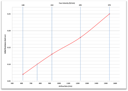
In order for a filter to meet the system's specifications for airflow and pressure drop, it must be rated by the manufacturer to simultaneously provide more than the specified airflow at less than the specified pressure drop. It is unlikely that a filter will be available that is rated to have the exact airflow and pressure drop ratings specified, so filters should be selected that are rated to have less than the specified pressure drop at the specified airflow rate, otherwise select filters that are rated to have greater than the specified airflow rate at the specified pressure drop. See Figure 4-4 for an example of an installer's filter grille sticker that provides an air filter rating specification for minimum airflow of 750 cfm at maximum pressure drop 0.1 inch w.c..
Air filter manufacturers may make supplementary product information available to consumers to assist with selecting the proper replacement filters. This product information may provide more detailed information about their filter model airflow and pressure drop performance - details such as airflow and pressure drop values that are intermediate values that lie between the values shown on their product label. The information may be published in tables, graphs, or presented in software applications available on the internet or at the point of sale.
Figure 4-4 below shows a graphical representation of the initial resistance (pressure drop) and airflow rate ordered pairs given on the example air filter manufacturer's label shown in Figure 4-3 above. The graph in Figure 4-4 makes it possible to visually determine the airflow rate at 0.1 inch w.c. pressure drop for which the values are not shown on the manufacturer's filter label.
If there is no supplementary manufacturer information available and it is necessary to determine a filter model's performance at an airflow rate or pressure drop, linear interpolation may be used. Example formulas for are shown below.
This method may be used to determine an unknown pressure drop corresponding to a known airflow rate by use of Equation 4-8a, or it may also be used to determine an unknown airflow rate corresponding to a known pressure drop by use of Equation 4-8b.
Equation 4-8a
p = p1 + [(f-f1) ÷ (f2-f1)] x (p2 – p1)
where:
f = a known flow value between f1 and f2
p = the unknown pressure drop value corresponding to f
p1 and p2 = known values that are less than and greater than p respectively
f1 and f2 are the known values corresponding to p1 and p2
Equation 4-8b
f = f1 + [(p-p1) ÷ (p2-p1)] x (f2 – f1)
where:
p = a known pressure drop value between p1 and p2
f = the unknown flow value corresponding to p
f1 and f2 = known values that are less than and greater than f respectively
p1 and p2 are the known values corresponding to f1 and f2
See Example 4-7 for sample calculations that determine the filter's rated airflow corresponding to a known pressure drop specification (0.1 inch w.c.).
Figure 4-4: Plot of Pressure Drop vs. Airflow for a 20" X 30" X 1" Depth Air Filter
From Manufacturer Label Information
Source: California Energy Commission
Example 4-7: Filter Selection Using Linear Interpolation
Question
Does the air filter label in Figure 4-3 indicate the filter would meet the airflow (750 cfm) and pressure drop (0.1 inch w.c.) requirements shown on the installer filter grille sticker in figure 4-2? How the airflow rate at 0.1 inch w.c. for the manufacturer's filter label shown in Figure 4-3 be determined?
Answer
The filter must be rated to provide greater than 750 cfm at the specified 0.1 inch w.c. pressure drop, or equivalently: the filter must be rated to provide a pressure drop less than 0.1 inch w.c at the specified 750 cfm.
Referring to equation 4-8b, calculate the unknown value "f" in cfm that corresponds to the known value "p" of 0.1 inch w.c..
Referring to Figure 4-4: p1=0.7, p2=0.13, f1=615, f2=925, and applying Equation 4-8b:
615 + [(0.1-0.07) ÷ (0.13-0.07)] x (925-615) yields 770 cfm
Therefore, since the filter is rated for greater than 750 cfm at 0.1 inch w.c, the filter complies.
Example 4-8: Filter Sizing
Question
A 1,200 cfm furnace is being installed in a new dwelling unit. It has a 20" x 20" x 1” inch filter rack furnished with a 1 inch depth filter installed in the unit. Is this filter in compliance?
Answer
The nominal face area of the filter rack is 20 inches by 20 inches to equal 400 sq in and since it is a 1 inch filter, the face area may not be less than 1200 (cfm)/150 (ft/min) x144 (in2 / ft2) = 1,152 sq in. Therefore, this filter installation does not comply.
Example 4-9
Question
For the same 1200 cfm furnace, what other options are there?
Answer:
The filter will be in compliance if it has a depth of 2” or more, and is properly sized by the system designer such that the duct system as a whole will be capable of meeting the HERS verification for fan efficacy specified in Section 150.0(m)13.
Otherwise, the required total system filter face area of 1,152 sq inches must be met using multiple remote wall or ceiling filter grilles for which the sum of the face areas are equal to or greater than 1152 sq inches, and the filters must be rated for pressure drop of 0.1 inch w.c. or less at the design airflow rates of each filter grille.
For any filter, the pressure drop, efficiency, and length of time the filter can remain in operation without becoming fully loaded with dust can all be improved by using filters that are deeper than 1 inch. As the depth of the filter is increased, the pressure drop across the filter at the same face area will be greatly reduced.
Example 4-10
Question
A ductless split system is being installed in a home. Must a designated MERV 13 filter be used?
Answer
No, the filtration requirements do not apply unless there is at least 10 feet of duct is attached to the unit.
Example 4-11
Question
If a customer has allergies and wants a MERV 16 or better filter. Is this in compliance?
Answer
Yes, a filtration greater than MERV 13 meets (exceeds) the minimum particle removal efficiency requirement, thus may be used provided all other applicable requirements in 120.1(b)1 are complied with.
This section will cover compliance and enforcement, typical design solutions, energy consumption issues, and the requirements specified by ASHRAE 62.2 as amended in the 2019 Energy Standards. The key changes from 2016 to 2019, applicable to high-rise residential dwelling units, of ASHRAE 62.2 and Title 24 Part 6 amendments to 62.2 include:
a. ASHRAE 62.2 now covers mid-rise and high-rise residential occupancies as well as single-family detached and low-rise attached multifamily dwellings.
b. Compliance with required dwelling unit ventilation using variable mechanical ventilation systems (intermittent or variable operation) requires the average mechanical ventilation rate (in cfm) over a three-hour period to be greater than or equal to the ventilation rate used for continuous ventilation. More complicated control strategies may be used if the system operation complies with the “relative exposure” calculations in normative Appendix C of ASHRAE 62.2.
c. Two options for compliance with dwelling unit ventilation are allowed for multifamily attached dwelling units: (1) installation of a balanced ventilation system, or (2) installation of an exhaust or supply-only system accompanied by sealing to a leakage rate of not more than 0.3 cfm 50 per sq. ft. of dwelling unit enclosure surface area. Home Energy Rating System (HERS) verification of dwelling unit ventilation and any applicable envelope leakage is required in accordance with NA1 and NA2 procedures. Certified Acceptance Test Technicians (ATT) may perform these field verifications only if the Acceptance Test Technician Certification Provider (ATTCP) has been approved to provide this service.
d. Kitchen range hood fans are now required to be verified by a HERS rater. The new verification protocol requires comparing the installed model to ratings in the HVI directory of certified ventilation products to confirm the installed range hood is rated to meet the required airflow and sound requirements specified in ASHRAE 62.2. Kitchen range hood fans that exhaust more than 400 cfm at their minimum speed are exempt from this requirement. Kitchen range hoods are required to discharge the exhaust airflow to outside. Recirculation range hood types are not allowed.
Compliance with the dwelling unit ventilation airflow specified in ASHRAE 62.2 is required in new dwelling units. Alterations to components of existing buildings that previously met any requirements of ASHRAE 62.2 must continue to meet requirements upon completion of the alteration(s).
4.3.2.1 Key Requirements for Most Newly Constructed Buildings
a. A dwelling unit mechanical ventilation system shall be provided. Typical solutions are described in Section 4.3.2.5 below. The airflow rate provided by the system shall be confirmed through field verification and diagnostic testing in accordance with the applicable procedures specified in Reference Nonresidential Appendix NA2.2.
b. Kitchens and bathrooms shall have local exhaust fans vented to outdoors.
c. Clothes dryers shall be vented to outdoors.
4.3.2.2 Other Indoor Air Quality Design Requirements
a. Ventilation air shall come from outdoors. It should not be transferred from adjacent dwelling units, garages, unconditioned attics or crawl spaces.
b. Ventilation system controls should be labeled. The dwelling occupant should be provided with instructions on how to operate the system.
c. Combustion appliances should be properly vented. Exhaust systems should be designed to prevent back drafting.
d. Walls and openings between the dwelling and a garage should be sealed or gasketed.
e. Habitable rooms should have windows with an opening ventilation area of at least 4 percent of the floor area.
f. Mechanical systems including heating and air-conditioning systems that supply air to habitable spaces shall have MERV 13 filters or better and be designed to accommodate the system's air filter's rated pressure drop at the system's design airflow rate.
g. Dedicated air inlets (not exhaust) that are part of the ventilation system design should be located away from known sources of outdoor contaminants.
h. A carbon monoxide alarm should be installed in each dwelling unit in accordance with NFPA Standard 720.
4.3.2.3 Air-Moving Equipment Requirements
Air-moving equipment used to meet the dwelling unit ventilation requirement and the local ventilation exhaust requirement should be rated in terms of airflow and sound:
a. Dwelling unit ventilation and continuously operating local exhaust fans must be rated at a maximum of 1.0 sone.
b. Demand controlled local exhaust fans must be rated at a maximum of 3.0 sone.
c. Kitchen range hood fans must be rated at a maximum of 3.0 sone at one or more airflow settings greater than or equal to 100 cfm.
d. Remotely located air-moving equipment (mounted outside habitable spaces) are exempt from the sound requirements provided there is at least four feet of ductwork between the fan and the interior grille.
4.3.2.4 Compliance and Enforcement
Compliance with ASHRAE 62.2 requirements must be verified by the enforcement agency, except for the following requirements that must be HERS verified in accordance with the procedures in Nonresidential Appendix NA1 and NA2.2:
a. Dwelling unit ventilation airflow rate
b. HVI ratings for kitchen range hood fans
All applicable certificates of compliance, installation, and acceptance need be completed before the certificate of verification must be registered with an approved HERS provider.
4.3.2.5 Typical Solutions for Multifamily Dwelling Unit Ventilation
There are generally three system types available for meeting the dwelling unit ventilation requirement (refer to Residential Compliance Manual Section 4.6.2 for descriptions of the system types identified below):
a. Exhaust ventilation - air is exhausted from the dwelling unit and replaced by infiltration.
b. Supply ventilation - outdoor air is supplied directly to the dwelling unit after being filtered.
c. Balanced ventilation – may be a single packaged unit containing supply and exhaust fans that moves approximately the same airflow through a heat or energy recovery core, or may utilize separate fans without heat exchange. In both cases air supplied from outdoors must be filtered (see Section 4.3.1 for air filter requirements).
Exhaust and balanced systems are most frequently used in multifamily buildings, but supply ventilation may also be used. Exhaust (or supply) systems in low-rise buildings typically use individual fans located in the dwelling units that exhaust directly to outdoors.
Use of central ventilation fans/shafts that are shared with multiple dwelling units in the building are more common in mid-rise and high-rise buildings. When a supply or exhaust system provides dwelling unit ventilation to more than one dwelling unit, the airflows in each dwelling unit must be equal to or greater than the required (minimum) ventilation rate, and the airflows for each dwelling unit must also be balanced to be no more than 20 percent greater than the specified rate (see Standards Section 120.1(b)2Av). The specified rate for the systems that share a common fan/shaft may be the minimum rate required for compliance, in which case each of the dwellings receiving airflow from a common fan/shaft must have ventilation airflow no more than 20 percent greater than the minimum dwelling unit ventilation airflow required by Equation 120.1-B. If the lowest airflow provided to any of the dwellings served by the common fan/shaft is a specific percent value greater than the minimum required for compliance, then the each of the dwellings receiving airflow from that common fan/shaft must have ventilation airflow no more than 20 percent greater than that lowest dwelling unit ventilation airflow. For example, if the lowest ventilation airflow among all dwellings served by the common fan/shaft is 2 percent greater than the minimum required for compliance, then all dwellings served by the common fan/shaft must be balanced to have ventilation airflow that is no more than 22 percent greater than the minimum ventilation airflow required for compliance.
These systems must utilize balancing devices to ensure the dwelling-unit airflows can be adjusted to meet this balancing requirement. These system balancing devices may include but are not limited to constant air regulation devices, orifice plates, and variable speed central fans.
Since supply and exhaust ventilation system types are required to operate continuously in multifamily dwellings (see Section 120.1(b)2Aivb2), and since Central Fan Integrated (CFI) systems are prohibited from operating continuously to provide the required dwelling unit ventilation (see Section 120.1(b)2Aii, the CFI ventilation system type is not allowed to be used in multifamily dwellings. Refer to residential compliance manual Section 4.6.2.3 for descriptions of the CFI ventilation system type. Certified Acceptance Test Technicians (ATT) may perform these field verifications only if the Acceptance Test Technician Certification Provider (ATTCP) has been approved to provide this service.
Transfer air is the airflow between adjacent dwelling units in a multifamily building, which can be a major contributor to poor indoor air quality in the dwelling units. Transfer airflow is caused by differences in pressure between adjacent dwelling units, which forces air to flow through leaks in the dwelling unit enclosure. The pressure differences may be due to stack effects and wind effects, but unbalanced mechanical ventilation is also a major contributor to this problem. It is desirable to minimize or eliminate leaks in all of the dwelling enclosures in the building – to compartmentalize the dwellings - to prevent pollutants such as tobacco smoke, pollution generated from food preparation in the kitchen, odors, and other pollutants from being transferred to adjacent dwellings in the building.
Title 24 provides two compliance paths for mechanical ventilation that improve compartmentalization in multifamily buildings (choose one):
a. Install a balanced ventilation system. This may consist of either a single ventilation unit such as an energy recovery ventilator or heat recovery ventilation (HRV), or may consist of separate supply and exhaust fans that operate simultaneously and are controlled to balance the supply and exhaust airflows. The outdoor ventilation supply air must be filtered (MERV 13 or better).
b. Verify that the dwelling unit leakage is not greater than 0.3 cfm per sq. ft of dwelling unit enclosure area using the procedures in NA2.3 (blower door test). If the dwelling unit enclosure passes this blower door test, use of continuously operating supply ventilation systems, or continuously operating exhaust ventilation systems in that dwelling is allowed.
Nonresidential Appendix NA2.2.4 provides direction for measurement of supply, exhaust, and balanced system types. These measurement procedures are applicable when there is a fixed airflow rate required for compliance, such as for systems that operate continuously at a specific airflow rate or systems that operate intermittently at a fixed speed (averaged over any three-hour period), according to a fixed timer pattern for which the programmed pattern is verifiable by a HERS rater on site (Refer to ASHRAE 62.2 Section 4.5.1 Short Term Average Ventilation).
Variable or intermittent operation that complies with ASHRAE 62.2 Sections 4.5.2, and 4.5.3 complies with the dwelling unit mechanical ventilation requirements by use of varying ventilation airflow rates based on complicated calculations for relative exposure as specified in ASHRAE 62.2 normative appendix C. These calculation procedures provide the basis for "smart" ventilation controls implemented by use of digital controls that rely on the manufacturer's product-specific algorithms or software. Any ventilation system models that use these complex ventilation system controls in a ventilation product designed to be used to comply with Energy Standards Section 120.1 must submit an application to the Energy Commission to have the ventilation technology approved. These manufacturers are expected to provide with their applications, evidence that the system will perform to provide the required dwelling unit mechanical ventilation, and also provide a method that could be used by a HERS rater to verify that an installed system is operating as designed.
Listings of systems approved by the Energy Commission and certified by the manufacturer are located at the following URL:
http://www.energy.ca.gov/title24/equipment_cert/imv/
Dwelling unit ventilation systems may operate continuously or on a short-term basis. If fan operation is not continuous, the average ventilation rate over any three-hour period must be greater than or equal to the Qtot value calculated using Equation 4-9 in this section.
ASHRAE 62.2 provides for scheduled ventilation and real time control, but these control approaches require “equivalent exposure” calculations using methods in Normative Appendix C and complex controls would be required to operate the fan.
Use of a building infiltration credit is not applicable to calculation of the required dwelling unit mechanical ventilation for multifamily dwelling units.
When the performance compliance approach is used, the compliance software automatically calculates the ventilation rate based on Equations 4-9, and Qtot is reported on the NRCC-PRF-01-E.
The total ventilation rate is the combined volume of ventilation air provided by infiltration and the mechanical ventilation provided from fans, as follows:
Equation 4-9
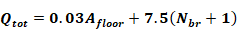
Where:
Qtot = total required ventilation rate (cfm)
Afloor = conditioned floor area (ft2)
Nbr= number of bedrooms (not less than one)
For multifamily units, the installed ventilation system must deliver the total ventilation rate Qtot calculated from Equation 4-9.
Example 4-12: Required Ventilation
Question
What is the required continuous ventilation rate for a three-bedroom, 1,800 sq. ft. dwelling unit?
Answer:
Equation 4-9 yields a total ventilation rate of 84 cfm

Example 4-13
Question
An HRV that delivers 80 cfm of outdoor air and exhausts 90 cfm of indoor air is being installed. The dwelling is required to have 86 cfm of ventilation airflow. Can this system be used?
Answer:
No. For balanced systems the supply and exhaust airflows can be averaged, and in this case, they average 85 cfm, which is slightly less than required 86 cfm.
The nominal rating of a fan can be very different than what it actually delivers when installed and connected to ductwork. Designers should always include some safety margin when sizing equipment. The length and size of ducting should be used to calculate the pressure drop. This is why dwelling unit ventilation rates must be verified by a HERS rater.
Example 4-14
Question
A 2,300 sq. ft. dwelling unit has exhaust fans running continuously in two bathrooms providing a total exhaust flow rate of 90 cfm, but the requirement is 98 cfm. What are the options for providing the additional 8 cfm?
Answer:
The required additional cfm could be provided either by increasing the size of either or both exhaust fans such that the combined airflow exceeds 98 cfm. Some fan models have speed adjustments which allow adjusting the fan airflow in the field after installation.
Example 4-15
Question
A builder wants to provide controls that disable the ventilation system so it does not bring in outside air during the hottest two hours of the day. Equation 4-9 determined the system needs to be 80 cfm continuous. How large must the fan be?
Answer:
If the average rate over three hours is 80 cfm and the fan only operates one hour, then it must be capable of delivering 3 x 80 = 240 cfm. ASHRAE 62.2 does not allow averaging ventilation over more than a three-hour period.
4.3.2.6 Control and Operation
From ASHRAE 62.2, Section 4.4, Control and Operation. A readily
accessible manual on/off control, including but not limited to a fan
switch or a dedicated branch-circuit overcurrent device, shall be provided.
Controls shall include text or an icon indicating the system’s
function.
Exception: For multifamily dwelling units, the manual on/off control shall not be required to be readily accessible.
From Standards Section 150.0(o)1I: Compliance with ASHRAE 62.2 Section 4.4 (Control and Operation) shall require manual switches associated with dwelling unit ventilation systems to have a label clearly displaying the following text, or equivalent text: "This switch controls the indoor air quality ventilation for the home. Leave it on unless the outdoor air quality is very poor."
ASHRAE 62.2 requires that the ventilation system have an override control that is accessible to the occupants. The control must be capable of being accessed quickly and easily by the occupants. It can be a labeled wall switch, a circuit breaker located in the electrical panel, or it may be integrated into a labeled wall-mounted control. It cannot be buried in the insulation in the attic or inside the installed ventilation fan cabinet. The dwelling unit occupant must have easy access to modify the fan control settings or turn off the system if necessary.
For multifamily dwelling units, the manual on/off control is not required to be readily accessible to the dwelling unit occupant(s). Instead, the ventilation control may be located such that it is readily accessible to the person in charge of the multifamily building maintenance. This control strategy may be appropriate for multifamily buildings that use unbalanced (supply-only or exhaust-only) system types for which the Energy Standards require that all of the ventilation systems in the building operate continuously. Continuous operation of all ventilation fans in the building tends to minimize ventilation fan-induced pressure differences between adjoining dwellings, thus to reduce the leakage of transfer air between dwelling units. Transfer airflows that that originate in one dwelling unit may adversely affect the indoor air quality of the other dwelling units in the building if the transfer air contains pollutants such as tobacco smoke and PM2.5 from kitchen range cooking activities.
Balanced dwelling unit ventilation systems may operate continuously. If fan operation is not continuous, the average ventilation rate over any three-hour period must be greater than or equal to the minimum dwelling unit ventilation rate calculated by Equation 4-9 above.
Bathroom exhaust fans may serve a dual purpose to provide whole-dwelling unit ventilation operating at a low constant airflow rate, and also provide local demand controlled ventilation (DCV) at a higher "boost" airflow rate when needed. For these system types, the continuous whole-building airflow operation must have an on/off override which may be located in the bathroom or in a remote accessible location. The "boost" function is controlled by a separate wall switch located in the bathroom, or by a motion sensor or humidistat located in the bathroom.
Time-of-day timers or duty cycle timers can be used to control intermittent dwelling unit ventilation. Manual crank timers cannot be used, since the system must operate automatically without intervention by the occupant.
See Section 4.3.2.4.4 for additional information about Energy Commission approval of ventilation controls.
Example 4-16: Control Options
Question
A bathroom exhaust fan is used to provide dwelling unit ventilation. The fan is designed to be operated by a typical wall switch. Is a label on the wall plate necessary to comply with the requirement that controls be “appropriately labeled”?
Answer:
Yes. Since the fan is providing the required dwelling unit ventilation, a label is needed to inform the occupant that this switch controls the indoor air quality ventilation for the home, and directs the occupant to leave it on unless the outdoor air quality is very poor. If the exhaust fan were serving only the local exhaust requirement for the bathroom, then a label would not be required.
4.3.2.7 Local Exhaust (Section 5 of ASHRAE 62.2)
From ASHRAE 62.2,
5.1 Local Mechanical Exhaust. A local mechanical exhaust system shall be installed in each kitchen and bathroom. Nonenclosed kitchens shall be provided with a demand-controlled mechanical exhaust system meeting the requirements of Section 5.2. Each local ventilation system for all other kitchens and bathrooms shall be either one of the following two:
a. A demand-controlled mechanical exhaust system meeting the requirements of Section 5.2
b. A continuous mechanical exhaust system meeting the requirements of Section 5.3.
Exception: Alternative Ventilation. Other design methods may be used to provide the required exhaust rates when approved by a licensed design professional.
5.2 Demand-Controlled Mechanical Exhaust. A local mechanical exhaust system shall be designed to be operated as needed.
5.2.1 Control and Operation. Demand-controlled mechanical exhaust systems shall be provided with at least one of the following controls:
a. A readily accessible occupant-controlled on/off control.
b. An automatic control that does not impede occupant on control.
5.2.2 Ventilation Rate. The minimum airflow rating shall be at least the amount indicated in Table 5.1.
5.3 Continuous Mechanical Exhaust. A mechanical exhaust system shall be installed to operate continuously. The system may be part of a balanced mechanical system. See Chapter 10 of ASHRAE Guideline 24 for guidance on selection of methods.
5.3.1 Control and Operation. A readily accessible manual on/off control shall be provided for each continuous mechanical exhaust system. The system shall be designed to operate during all occupiable hours.
Exception: For multifamily dwelling units, the manual on/off control shall not be required to be readily accessible.
5.3.2 Ventilation Rate. The minimum delivered ventilation shall be at least the amount indicated in Table 5.2 during each hour of operation.
From ASHRAE 62.2 - Table 5-1 Demand-Controlled Local Ventilation Exhaust Airflow Rates
|
Application |
Airflow |
|
Enclosed Kitchen |
•Vented range hood (including appliance-range hood combinations): 100 cfm (50 L/s) •Other kitchen exhaust fans, including downdraft: 300 cfm (150 L/s) or a capacity of 5 ach |
|
Non-Enclosed Kitchen |
•Vented range hood (including appliance-range hood combinations): 100 cfm (50 L/s) •Other kitchen exhaust fans, including downdraft: 300 cfm (150 L/s) |
|
Bathroom |
50 cfm (25 L/s) |
From ASHRAE 62.2 - TABLE 5.2 Continuous Local Ventilation Exhaust Airflow Rates
|
Application |
Airflow |
|
Enclosed Kitchen |
5 ach, based on kitchen volume |
|
Bathroom |
20 cfm (10 L/s) |
Local exhaust (sometimes called spot ventilation) has long been required for bathrooms and kitchens to remove moisture and odors at their source. Building codes have required an operable window or an exhaust fan in bathrooms for many years and have generally required kitchen exhaust either directly through a fan or indirectly through a recirculating range hood and an operable window. The Energy Standards recognize the limitations of these indirect methods of reducing moisture and odors and requires that these spaces be mechanically exhausted directly outdoors, even if windows are present. Moisture condensation on indoor surfaces is a leading cause of mold and mildew in buildings. The occurrence of asthma is also associated with high interior relative humidity. Therefore, it is important to exhaust the excess moisture from bathing and cooking directly at the source.
The Energy Standards require that each kitchen and bathroom have an exhaust fan. Generally, this will be a dedicated exhaust fan in each room that requires local exhaust. Ventilation systems that exhaust air from multiple rooms using a duct system connected to a single exhaust fan are allowed as long as the minimum local exhaust requirement is met in all rooms served by the system. The standards define kitchens as any room containing cooking appliances. The definition of a bathroom is any room containing a bathtub, shower, spa, or other similar source of moisture. A room containing only a toilet is not required to have an exhaust fan; ASHRAE 62.2 assumes there is an adjacent bathroom with local exhaust.
Building codes may require that fans used for kitchen range hood exhaust ventilation be safety-rated by Underwriters Laboratories Inc. (UL) or some other testing agency for the particular location and/or application. Typically, these requirements address fire safety issues of fans placed within an area defined by a set of lines at 45 degrees F outward and upward from the cooktop. Few bathroom exhaust fans will have this rating, so cannot be used in these locations.
Example 4-17: Local Exhaust Required for Toilet
Question
A home is being built with 2.5 baths. The half-bath consists of a room with a toilet and sink. Is local exhaust required for the half bath?
Answer
No. Local exhaust is required only for bathrooms, which are defined by the Energy Standards as rooms with a bathtub, shower, spa or some other similar source of moisture. This does not include a simple sink for occasional hand washing.
Example 4-18
Question
The master bath suite in a dwelling has a bathroom with a shower, spa and sinks. The toilet is in a separate, adjacent room with a full door. Where do I need to install local exhaust fans?
Answer
The standards require local exhaust only in the bathroom, not the separate toilet room.
The Energy Standards require that local exhaust fans be designed to be operated by the occupant. This usually means that a wall switch or some other control is accessible and obvious. There is no requirement to specify where the control or switch needs to be located, but bathroom exhaust fan controls are generally located next to the light switch, and kitchen exhaust fan controls are generally integrated into the range hood, mounted on the wall or counter adjacent to the range hood.
Bathrooms can use a variety of exhaust strategies. They can use ceiling-mounted exhaust fans or may use a remotely mounted fan ducted to two or more exhaust grilles. Demand-controlled local exhaust can be integrated with the dwelling unit ventilation system to provide both functions. Kitchens can have range hood exhaust fans, down-draft exhausts, ceiling- or wall-mounted exhaust fans, or pickups for remote-mounted inline exhaust fans. Generally, HVR/ energy recovery ventilator manufacturers do not allow exhaust ducting from the kitchen, because of the heat, moisture, grease, and particulates that should not enter the heat exchange core. Building codes require kitchen exhaust fans to be connected to metal ductwork for fire safety.
Example 4-19: Ducting Kitchen Exhaust to the Outdoors
Question
How does one know what kind of duct to use? If a builder is familiar with recirculating hoods and now needs to vent to outdoors, what should he or she look for?
Answer
A kitchen range hood or downdraft duct is generally a smooth metal duct that is sized to match the outlet of the ventilation device. It is often a six-inch or seven-inch-round duct, or the range hood may have a rectangular discharge. If it is rectangular, the fan will typically have a rectangular-to-round adapter included. Always use a terminal device on the roof or wall that is sized to be at least as large as the duct. Try to minimize the number of elbows used.
Question
What are the requirements in a specific area?
Answer
Ask a local code enforcement agency for that information. Some enforcement agencies will accept metal flex, some will not.
The choice of control is left to the designer. It can be a manual switch or automatic control, like an occupancy sensor. Some exhaust fans have multiple speeds, and some fan controls have a delay-off function that operates the exhaust fan for a set time after the occupant leaves the bathroom. New control strategies continue to come to the market. The only requirement is that there is a control. Title 24, Part 11 may specify additional requirements for the control and operation of intermittent local exhaust.
A minimum exhaust airflow of 100 cfm is required for vented kitchen range hoods, and 300 cfm or 5 ACH is required for other kitchen exhaust fans. A minimum exhaust airflow of 50 cfm is required for bathroom fans.
The 100 cfm requirement for the range hood or microwave/hood combination is the minimum to adequately capture the moisture, particulates, and other products of cooking and/or combustion. In kitchens that are enclosed, the exhaust requirement can also be met with either a ceiling or wall-mounted exhaust fan or with a ducted fan or ducted ventilation system that can provide at least five air changes of the kitchen volume per hour. Recirculating range hoods that do not exhaust pollutants to the outside cannot be used to meet the requirements of ASHRAE Standard 62.2 unless paired with an exhaust system that can provide at least five air changes of the kitchen volume per hour.
The Energy Standards require verification that range hoods are HVI certified to provide at least one speed setting at which they can deliver at least 100 cfm at a noise level of 3 sones or less. Verification must be in accordance with the procedures in Reference Nonresidential Appendix NA2.2.4.1.3. Range hoods that have a minimum airflow setting exceeding 400 cfm are exempt from the noise requirement. HVI listings are available at:
https://www.hvi.org/proddirectory/CPD_Reports/section_1/index.cfm
ASHRAE Standard 62.2 limits exhaust airflow when atmospherically vented combustion appliances are located inside the pressure boundary. This is particularly important to observe when large range hoods are installed. Refer to the Residential Compliance Manual Section 4.6.8.4 for more information.
Example 4-20: Ceiling or Wall Exhaust vs Demand-Controlled Range Hood in an Enclosed Kitchen
Question:
A dwelling has an enclosed kitchen that is 12 ft. by 14 ft. with a 10 ft. ceiling. What size ceiling exhaust fan or range hood fan is required?
Answer
If a range hood exhaust is not used, either 300 cfm or 5 ACH minimum airflow is required. The kitchen volume is 12 ft. x 14 ft. x 10 ft. = 1680 ft3. Five air changes are a flow rate of 1680 ft³ x 5/ hr ÷ 60 min/hr = 140 cfm. This kitchen must have a ceiling or wall exhaust fan of 140 cfm. Otherwise a vented range hood fan that provides at least 100 cfm is required.
The Energy Standards allow the designer to install a local exhaust system that operates without occupant intervention continuously and automatically during all occupiable hours. Continuous local exhaust may be specified for compliance when the local exhaust ventilation system is also used to comply with the airflow rate required for continuous dwelling unit ventilation, as long as the fan airflow meets both the local and dwelling unit airflow rates. Continuous local exhaust may also be part of a pickup for a remote fan or HRV/ energy recovery ventilator system.
Continuously operating bathroom fans must operate at a minimum of 20 cfm. Continuously operating kitchen fans are only permitted for enclosed kitchens. Refer to Tables 5.1 and 5.2 in ASHRAE 62.2 (shown also in section 4.3.2.7 above) for other local demand controlled and continuous exhaust requirements.
Example 4-21: Continuous Kitchen Exhaust
Question
A new dwelling has an open-design, 12 ft by 18 ft ranch kitchen with 12 ft cathedral ceilings. What airflow rate will be required for a continuous exhaust fan?
Answer
A continuous exhaust fan cannot be used in non-enclosed kitchens. A vented range hood must be provided.
4.3.2.8 Other Requirements (Section 6 of ASHRAE 62.2)
See section 4.6.8 in the Residential Compliance Manual for additional information about other requirements from Section 6 of ASHRAE 62.2 that are adopted by Title 24, Part 6.
The 2019 Energy Standards changed the way naturally ventilated spaces are calculated by adopting ASHRAE 62.1. Under these new requirements, naturally ventilated spaces or portions of spaces must be permanently open to and within certain distances of operable wall openings to the outdoors. The space being ventilated, the size of the operable opening and the control of the opening are all considered under these new requirements. Naturally ventilated spaces must also include a mechanical ventilation system that complies with §120.1(c)3 as described in Section 4.3.3., except when the opening to the outdoors is permanently open or has controls that prevent the opening from being closed during periods of expected occupancy. This requirement for mechanical ventilation back-up to a naturally ventilated space protects the occupants from times or events where the outdoor air is not adequate for ventilation and does not rely on an individual to open the opening.
The space to be naturally ventilated is determined based on the configuration of the walls (cross-ventilation, single-sided or adjacent walls) and the ceiling height. For spaces with an operable opening on only one side of the space, only the floor area within two times the ceiling height from the opening is permitted to be naturally ventilated. For spaces with operable openings on two opposite sides of the space, only the floor areas within five times the ceiling height from the openings are permitted to be naturally ventilated. For spaces with operable openings on two adjacent sides of the space (two sides of a corner), only the floor areas along lines connecting the two openings that are within five times the ceiling height meet the requirement. Floor areas not along these lines connecting the windows must meet the one side or two opposite side opening calculation to be permitted to be naturally ventilated. The ceiling height for all of these cases is the minimum ceiling height, except for when the ceiling is sloped upwards from the opening. In that case, the ceiling height is calculated as the average within 20 feet of the opening.
Spaces or portions of space being naturally ventilated must be permanently open to operable walls openings directly to the outdoors. The minimum openable area is required to be 4 percent of the net occupiable floor area being naturally ventilated. Where openings are covered with louvers or otherwise obstructed, the openable area must be based on the free unobstructed area through the opening. Where interior spaces without direct openings to the outdoors are ventilated through adjoining rooms, the opening between rooms must be permanently unobstructed and have a free area of not less than 8 percent of the area of the interior room nor less than 25 sq. ft.
The means to open required operable openings must be readily accessible to building occupants whenever the space is occupied. The operable opening must be monitored to coordinate the operation of the operable opening and the mechanical ventilation system. This is achieved through window contact switches or another type of relay switch that interlocks the operable opening with the mechanical ventilation system. [§140.4(n)]
Mechanical outdoor ventilation must be provided for all spaces normally occupied. The Energy Standards require that a mechanical ventilation system provide outdoor air equal to or exceeding the ventilation rates required for each of the spaces that it serves. At the space, the required ventilation can be provided either directly through supply air or indirectly through transfer of air from the plenum or an adjacent space (see 4.3.6 for updates to transfer air classification). The required minimum ventilation airflow at the space can be provided by an equal quantity of supply or transfer air. At the air-handling unit, the minimum outside air must be the sum of the ventilation requirements of each of the spaces that it serves. The designer may specify higher outside air ventilation rates based on the owner’s preference or specific ventilation needs associated with the space. However, specifying more ventilation air than the minimum allowable ventilation rates increases energy consumption and electrical peak demand and increases the costs of operating the HVAC equipment. Thus the designer should have a compelling reason to specify higher design minimum outside air rates than the calculated minimum outside air requirements.
The minimum outside air (OSA) as measured by acceptance testing, is required to be within 10 percent of the design minimum for both VAV and constant volume units. The design minimum outside air can be no less than the calculated minimum outside air
In summary:
1. Ventilation compliance at the space is satisfied by providing supply and/or transfer air.
2. Ventilation compliance at the air handling system level is satisfied by providing, at minimum, the outdoor air that represents the sum of the ventilation requirements of all the spaces that it serves.
For each space requiring mechanical ventilation the ventilation rates must be the greater of either:
1. The conditioned floor area of the space, multiplied by the area outdoor air rate (Ra) from Table 4-12. This provides dilution for the building-borne contaminants like off-gassing of paints and carpets, or
2. For spaces designed for an expected number of occupants or spaces with fixed seating, the outdoor airflow rate to the zone must be 15 cfm per person, multiplied by the expected number of occupants. For spaces with fixed seating (such as a theater or auditorium), the expected number of occupants is the number of fixed seats or as determined by the California Building Code.
|
Occupancy Category |
Area Outdoor Air rate1 Ra |
Min Air Rate for DCV2 |
Air Class2 |
Notes | |
|
cfm/ft2 |
cfm/ft2 | ||||
|
Educational Facilities | |||||
|
Daycare (through age 4) |
0.21 |
0.15 |
2 |
| |
|
Daycare sickroom |
0.15 |
|
3 |
| |
|
Classrooms (ages 5-8) |
0.38 |
0.15 |
1 |
| |
|
Classrooms (age 9 -18) |
0.38 |
0.15 |
1 |
| |
|
Lecture/postsecondary classroom |
0.38 |
0.15 |
1 |
F | |
|
Lecture hall (fixed seats) |
- |
0.15 |
1 |
F | |
|
Art classroom |
0.15 |
|
2 |
| |
|
Science laboratories |
0.15 |
|
2 |
| |
|
University/college laboratories |
0.15 |
|
2 |
| |
|
Wood/metal shop |
0.15 |
|
2 |
| |
|
Computer lab |
0.15 |
|
1 |
| |
|
Media center |
0.15 |
|
1 |
A | |
|
Music/theater/dance |
1.07* |
0.15 |
1 |
F | |
|
Multiuse assembly |
0.50 |
0.15 |
1 |
F | |
|
Food and Beverage Service | |||||
|
Restaurant dining rooms |
0.50 |
0.15 |
2 |
| |
|
Cafeteria/fast-food dining |
0.50 |
0.15 |
2 |
| |
|
Bars, cocktail lounges |
0.50 |
0.20 |
2 |
| |
|
Kitchen (cooking) |
0.15 |
|
2 |
| |
|
General | |||||
|
Break rooms |
0.50 |
0.15 |
1 |
F | |
|
Coffee stations |
0.50 |
0.15 |
1 |
F | |
|
Conference/meeting |
0.50 |
0.15 |
1 |
F | |
|
Corridors |
0.15 |
|
1 |
F | |
|
Occupiable storage rooms for liquids or gels |
0.15 |
|
2 |
B | |
|
Hotels, Motels, Resorts, Dormitories | |||||
|
Bedroom/living room |
0.15 |
|
1 |
F | |
|
Barracks sleeping areas |
0.15 |
|
1 |
F | |
|
Laundry rooms, central |
0.15 |
|
2 |
| |
|
Laundry rooms within dwelling units |
0.15 |
|
1 |
| |
|
Lobbies/pre-function |
0.50 |
0.15 |
1 |
F | |
|
Multipurpose assembly |
0.50 |
|
1 |
F | |
|
Office Buildings | |||||
|
Breakrooms |
0.50 |
0.15 |
1 |
| |
|
Main entry lobbies |
0.50 |
0.15 |
1 |
F | |
|
Occupiable storage rooms for dry materials |
0.15 |
|
1 |
| |
|
Office space |
0.15 |
|
1 |
F | |
|
Reception areas |
0.15 |
|
1 |
F | |
|
Telephone/data entry |
0.15 |
|
1 |
F | |
|
Miscellaneous Spaces | |||||
|
Bank vaults/safe deposit |
0.15 |
|
2 |
F | |
|
Banks or bank lobbies |
0.15 |
|
1 |
F | |
|
Computer (not printing) |
0.15 |
|
1 |
F | |
|
Freezer and refrigerated spaces (<50oF) |
- |
|
2 |
E | |
|
General manufacturing (excludes heavy industrial and process using chemicals) |
0.15 |
|
3 |
| |
|
Pharmacy (prep. Area) |
0.15 |
|
2 |
| |
|
Photo studios |
0.15 |
|
1 |
| |
|
Shipping/receiving |
0.15 |
|
2 |
B | |
|
Sorting, packing, light assembly |
0.15 |
|
2 |
| |
|
Telephone closets |
0.15 |
|
1 |
| |
|
Transportation waiting |
0.50 |
0.15 |
1 |
F | |
|
Warehouses |
0.15 |
|
2 |
B | |
|
All others |
0.15 |
|
2 |
| |
|
Public Assembly Spaces | |||||
|
Auditorium seating area |
1.07a |
0.15 |
1 |
F | |
|
Places of religious worship |
1.07a |
0.15 |
1 |
F | |
|
Courtrooms |
0.19a |
0.15 |
1 |
F | |
|
Legislative chambers |
0.19a |
0.15 |
1 |
F | |
|
Libraries (reading rooms and stack areas) |
0.15 |
|
1 |
| |
|
Lobbies |
0.50 |
0.15 |
1 |
F | |
|
Museums (children’s) |
0.25 |
0.15 |
1 |
| |
|
Museums/galleries |
0.25 |
0.15 |
1 |
F | |
|
Residential | |||||
|
Common corridors |
0.15 |
|
1 |
F | |
|
Retail | |||||
|
Sales (except as below) |
0.25 |
0.20 |
2 |
| |
|
Mall common areas |
0.25 |
0.15 |
1 |
F | |
|
Barbershop |
0.40 |
|
2 |
||
|
Beauty and nail salons |
0.40 |
|
2 |
| |
|
Pet shops (animal areas) |
0.25 |
0.15 |
2 |
| |
|
Supermarket |
0.25 |
0.20 |
1 |
F | |
|
Coin-operated laundries |
0.30 |
|
2 |
| |
|
Sports and Entertainment | |||||
|
Gym, sports arena (play area) |
0.50 |
0.15 |
2 |
E | |
|
Spectator areas |
0.50 |
0.15 |
1 |
F | |
|
Swimming (pool) |
0.15 |
|
2 |
C | |
|
Swimming (deck) |
0.50 |
0.15 |
2 |
C | |
|
Disco/dance floors |
1.50 |
0.15 |
2 |
F | |
|
Health club/aerobics room |
0.15 |
|
2 |
| |
|
Health club/weight rooms |
0.15 |
|
2 |
| |
|
Bowling alley (seating) |
1.07 |
0.15 |
1 |
| |
|
Gambling casinos |
0.68 |
0.15 |
1 |
| |
|
Game arcades |
0.68 |
0.15 |
1 |
| |
|
Stages, studios |
0.50 |
0.15 |
1 |
D, F | |
|
General notes: 1 Ra was determined as being the larger of the area method and the default per person method. The occupant density used in the per person method was assumed to be one half of the maximum occupant load assumed for egress purposes in the California Building Code. 2If this column specifies a minimum cfm/ft2 then it shall be used to comply with Section 120.1(d)4E. Specific notes: A – For high-school and college libraries, the values shown for “Public Assembly Spaces – Libraries” shall be used. B – Rate may not be sufficient where stored materials include those having potentially harmful emissions. C – Rate does not allow for humidity control. “Deck area” refers to the area surrounding the pool that is capable of being wetted during pool use or when the pool is occupied. Deck area that is not expected to be wetted shall be designated as an occupancy category. D – Rate does not include special exhaust for stage effects such as dry ice vapors and smoke. E – Where combustion equipment is intended to be used on the playing surface or in the space, additional dilution ventilation, source control, or both shall be provided. F – Ventilation air for this occupancy category shall be permitted to be reduced to zero when the space is in occupied-standby mode | |||||
|
Source: California Energy Commission, 2019 Building Energy Efficiency Standards, Table 120.1-A | |||||
As previously stated, each ventilation system must provide outdoor ventilation air as follows:
1. For a ventilation system serving a single space, the required system outdoor airflow is equal to the design outdoor ventilation rate of the space.
2. For a ventilation system serving multiple spaces, the required outdoor air quantity delivered by the system must not be less than the sum of the required outdoor ventilation rate to each space. The Energy Standards do not require that each space actually receive its exact calculated outdoor air quantity. Instead, the supply air to any given space may be any combination of recirculated air, outdoor air, or air transferred directly from other spaces, provided:
a. The total amount of outdoor air delivered by the ventilation system(s) to all spaces is at least as large as the sum of the space design quantities.
b. Each space always receives supply airflow, including recirculated air and/or transfer air, no less than the calculated outdoor ventilation rate.
c. When using transfer air, none of the spaces from which air is transferred has any unusual sources of contaminants.
Example 4-9: Ventilation for a Two-Room Building
Question
Consider a building with two spaces, each having an area of 1,000 sq ft. One space is used for general administrative functions, and the other is used as a classroom. It is estimated that the office will contain seven people, and the classroom will contain 50 people (fixed seating). What are the required outdoor ventilation rates?
Answer
1. For the office area, the design outdoor ventilation air is the larger of:
7 people x 15 cfm/person = 105 cfm; or
1,000 ft² x 0.15 cfm/ft² = 150 cfm
For this space, the design ventilation rate is 150 cfm.
2. For the classroom, the design outdoor ventilation air is the larger of:
50 people x 15 cfm/person = 750 cfm; or
1,000 ft² x 0.38 cfm/ft² = 380 cfm
For this space the design ventilation rate is 750 cfm.
Assume the total supply air necessary to satisfy cooling loads is 1,000 cfm for the office and 1,500 cfm for the classroom. If each space is served by a separate system, then the required outdoor ventilation rate of each system is 150 cfm and 750 cfm, respectively. This corresponds to a 15 percent outside air fraction in the office HVAC unit, and 50 percent in the classroom unit.
If both spaces are served by a central system, then the total supply will be (1,000 + 1,500) cfm = 2500 cfm. The required outdoor ventilation rate is (150 + 750) = 900 cfm total. The actual outdoor air ventilation rate for each space is:
Office outside air = 900 cfm x (1,000 cfm / 2,500 cfm) = 360 cfm
Classroom outside air = 900 cfm x (1,500 cfm / 2,500 cfm) = 540 cfm
While this simplistic analysis suggests that the actual outside air cfm to the classroom is less than design (540 cfm vs. 750 cfm), the analysis does not take credit for the dilution effect of the air recirculated from the office. The office is over-ventilated (360 cfm vs. 150 cfm) so the concentration of pollutants in the office return air is low enough that it can be used, along with the 540 cfm of outdoor air, to dilute pollutants in the classroom. The Energy Standards allow this design provided that the system always delivers at least 750 cfm to the classroom (including transfer or recirculated air), and that any transfer air is free of unusual contaminants.
The exhaust ventilation requirements are new for the 2019 Energy Standards. They are aligned with ASHRAE 62.1 and requires certain occupancy categories to be exhausted to the outdoors, as listed in Table 4-1. Exhaust flow rates must meet or exceed the minimum rates specified in 4-13. The spaces listed are expected to have contaminants not generally found in adjacent occupied spaces. Therefore, the air supplied to the space to replace the air exhausted may be any combination of outdoor air, recirculated air, and transfer air – all of which are expected to have low or zero concentration of the pollutants generated in the listed spaces. For example, the exhaust from a toilet room can draw air from either the outdoors, adjacent spaces, or from a return air duct or plenum. Because these sources of makeup air have essentially zero concentration of toilet-room odors, are equally good at diluting odors in the toilet room.
The rates specified must be provided during all periods when the space is expected to be occupied, similar to the requirement for ventilation air.
|
Occupancy Category |
Exhaust Rate (cfm/unit2) |
Exhaust Rate (cfm/ft2) |
Air Class |
Notes |
|
Arenas |
- |
0.50 |
1 |
B |
|
Art classrooms |
- |
0.70 |
2 |
|
|
Auto repair rooms |
- |
1.5 |
2 |
A |
|
Barber shops |
- |
0.50 |
2 |
|
|
Beauty and nail salons |
- |
0.60 |
2 |
|
|
Cells with toilet |
- |
1.00 |
2 |
|
|
Copy, printing rooms |
- |
0.50 |
2 |
|
|
Darkrooms |
- |
1.00 |
2 |
|
|
Educational science laboratories |
- |
1.00 |
2 |
|
|
Janitor closets, trash rooms, recycling |
- |
1.00 |
3 |
|
|
Kitchenettes |
- |
0.30 |
2 |
|
|
Kitchens – commercial |
- |
0.70 |
2 |
|
|
Locker rooms for athletic or industrial facilities |
- |
0.50 |
2 |
|
|
All other locker rooms |
- |
0.25 |
2 |
|
|
Shower rooms |
20/50 |
- |
2 |
G,H |
|
Paint spray booths |
- |
- |
4 |
F |
|
Parking garages |
- |
0.75 |
2 |
C |
|
Pet shops (animal areas) |
- |
0.90 |
2 |
|
|
Refrigerating machinery rooms |
- |
- |
3 |
F |
|
Soiled laundry storage rooms |
- |
1.00 |
3 |
F |
|
Storage rooms, chemical |
- |
1.50 |
4 |
F |
|
Toilets – private |
25/50 |
- |
2 |
E |
|
Toilets – public |
50/70 |
- |
2 |
D |
|
Woodwork shop/classrooms |
- |
0.50 |
2 |
|
|
Notes: A – Stands where engines are run shall have exhaust systems that directly connect to the engine exhaust and prevent escape of fumes. B – Where combustion equipment is intended to be used on the playing surface, additional dilution ventilation, source control, or both shall be provided. C – Exhaust shall not be required where two or more sides comprise walls that are at least 50% open to the outside. D – Rate is per water closet, urinal, or both. Provide the higher rate where periods of heavy use are expected to occur. The lower rate shall be permitted to be used otherwise. E – Rate is for a toilet room intended to be occupied by one person at a time. For continuous systems operation during hours of use, the lower rate shall be permitted to be used. Otherwise the higher rate shall be used. F – See other applicable standards for exhaust rate. G – For continuous system operation, the lower rate shall be permitted to be used. Otherwise the higher rate shall be used. H – Rate is per showerhead. | ||||
Source: California Energy Commission, Building Energy Efficiency Standards, Table 120.1-B
New in the 2019 Energy Standards is the concept of air classification, a process that assigns an air class number based on the occupancy category then sets limits on transferring or recirculating that air. This offers designers clear guidance on what can and cannot be used for transfer, makeup or recirculation air. In previous Energy Standards transfer air was allowed as long as it did not have “unusual sources of indoor air contaminants,” which left the enforcement of this rule to be arbitrary. Now, all spaces listed in Table 4-12 are assigned an air class and specific direction is given for each class, which is in alignment with ASHRAE 62.1.
Class 1: This class consists of air with low contaminant concentration, low sensory-irritation intensity, and inoffensive odor, suitable for recirculation or transfer to any space. Some examples include classrooms, lecture halls, and lobbies.
Class 2: This class consists of air with moderate contaminant concentration, mild sensory-irritation intensity, or mildly offensive odors. Class 2 air is suitable for recirculation or transfer to any space with Class 2 or Class 3 air, and that is utilized for the same or similar purpose and involves the same or similar pollutant sources. Class 2 air may be transferred to toilet rooms and to any Class 4 air occupancies. Class 2 air is not suitable for recirculation or transfer to dissimilar spaces with Class 2 or Class 3 air. It is also not suitable in spaces with Class 1 air, unless the Class 1 space uses an energy recovery device, then recirculation from leakage carryover or transfer from the exhaust side is permitted. In this case the amount of Class 2 air allowed to be transferred or recirculated shall not exceed 10 percent of the outdoor air intake flow. Thus, HVAC systems serving spaces with Class 2 air shall not share the same air handler as spaces with Class 1 air. Some examples include warehouses, restaurants, and auto repair rooms.
Class 3: This class consists of air with significant contaminant concentration, significant sensory-irritation intensity, or offensive odor that is suitable for recirculation within the same space. Recirculation of Class 3 air is only permitted within the space of origin. It is not suitable for recirculation or transfer to any other spaces. However, when a space uses an energy recovery device, then recirculation from leakage carryover or transfer from the exhaust side of the energy recovery device is permitted. In this case the amount of Class 3 air allowed to be transferred or recirculated shall not exceed 5 percent of the outdoor air intake flow. HVAC systems serving spaces with Class 3 air shall not share the same air handler serving spaces with Class 1 or Class 2 air. Some examples include general manufacturing (excludes heavy industrial and processes using chemicals) and janitor closets.
Class 4: This class consist of air with highly objectionable fumes or gases, as well as potentially dangerous particles, bioaerosols, or gases at concentrations high enough to be considered harmful. Class 4 air is not suitable for recirculation or transfer within the space or to any other space. No leakage of Class 4 air from energy recovery devices is allowed. Some examples include spray paint booths and chemical storage rooms.
In addition to Tables 4-12 and 4-13, the Energy Standards also include air classifications for specific airstreams and sources as detailed in Table 4-14. In the event that Tables 4-12, 4-13 and 4-14 do not list the space or location, the air classification of the most similar space listed in terms of occupant activities or building construction shall be used.
|
Description |
Air Class |
|
Diazo printing equipment discharge |
4 |
|
Commercial kitchen grease hoods |
4 |
|
Commercial kitchen hoods other than grease |
3 |
|
Laboratory hoods |
4a |
|
Hydraulic elevator machine room |
2 |
|
a. Air Class 4 unless determined otherwise by the Environmental Health and Safety professional responsible to the owner or to the owner’s designee. | |
|
Source: California Energy Commission, Building Energy Efficiency Standards, Table 120.1-C | |
For ancillary spaces that are designated as Class 1 air but support a Class 2 air space, re-designation of Class 1 air to Class 2 air for ancillary spaces to Class 2 areas is allowed. For example, a bank lobby is designated as Class 1 while bank vaults or safety deposit areas are designated at Class 2. The ancillary space to the bank safety deposit area can be re-designated to Class 2 from Class 1.
The Energy Standards allow air to be directly transferred from one space to another to meet part of the ventilation supply, provided the total outdoor quantity required by all spaces served by the building’s ventilation system is supplied by the mechanical systems. This method can be used for any space, but is particularly applicable to conference rooms, toilet rooms, and other rooms that have high ventilation requirements. Transfer air may be a mixture of air from multiple spaces or locations, in which case the air mixture must be classified at the mixed highest classification. Transfer air must meet the requirements of air classification and recirculation limitations, as described above.
Air may be transferred using any method that ensures a positive airflow. Examples include: dedicated transfer fans, exhaust fans, and fan-powered VAV boxes. A system having a ducted return may be balanced so that air naturally transfers into the space. Exhaust fans serving the space may discharge directly outdoors, or into a return plenum. Transfer systems should be designed to minimize recirculation of transfer air back into the space; duct work should be arranged to separate the transfer air intake and return points.
When each space in a two-space building is served by a separate constant volume system, the calculation and application of ventilation rate is straightforward, and each space will always receive its design outdoor air quantity. However, a central system serving both spaces does not deliver the design outdoor air quantity to each space. Instead, one space receives more than its allotted share, and the other less. This is because some spaces have a higher design outdoor ventilation rate and/or a lower cooling load relative to the other space.
When a return plenum is used to distribute outside air to a zonal heating or cooling unit, the outside air supply must be connected either:
1. Within 5 ft. of the unit; or
2. Within 15 ft. of the unit, with the air directed substantially toward the unit, and with a discharge velocity of at least 500 ft per minute.
Water source heat pumps and fan coils are the most common application of this configuration. The unit fans should be controlled to run continuously during occupancy in order for the ventilation air to be circulated to the occupied space.
Not all spaces are required to have a direct source of outdoor air. Transfer air is allowed from adjacent spaces with direct outdoor air supply if the system supplying the outdoor air is capable of supplying the required outdoor air to all spaces at the same time. Air classification and recirculation limitations will apply, as explained above. An example of an appropriate use of transfer would be in buildings having central interior space-conditioning systems with outdoor air supply, and zonal units on the perimeter without a direct outdoor air supply.
4.3.9.1 Outdoor Ventilation Air and VAV Systems
Except for systems employing Energy Commission-certified DCV devices or space occupancy sensors, the Energy Standards require that the minimum rate of outdoor air calculated per §120.1(c)3 be provided to each space at all times, when the space is normally occupied according to §120.1(d)1. For spaces served by VAV systems, the minimum supply setting of each VAV box should be no less than the design outdoor ventilation rate calculated for the space, unless transfer air is used. If transfer air is used, the minimum box position, plus the transfer air, must meet the minimum ventilation rate.
The design outdoor ventilation rate at the system level must always be maintained when the space is occupied, even when the fan has modulated to its minimum capacity §120.1(d)1. Section 4.3.15 describes mandated acceptance test requirements for outside air ventilation in VAV air handling systems where the minimum outside air will be measured at full flow with all boxes at minimum position.
Figure 4-5 shows a typical VAV system. In standard practice, the testing and balancing contractor sets the minimum position setting for the outdoor air damper during construction. It is set under the conditions of design airflow for the system, and remains in the same position throughout the full range of system operation, which does not meet code. As the system airflow drops, so will the pressure in the mixed air plenum. A fixed position on the minimum outdoor air damper will produce a varying outdoor airflow. Figure 4-5 shows this effect will be approximately linear (in other words, outdoor air airflow will drop directly in proportion to the supply airflow).
The following paragraphs present several methods used to dynamically control the minimum outdoor air in VAV systems.
Care should be taken to reduce the amount of outdoor air provided when the system is operating during the weekend or after hours with only a fraction of the zones active. Section 120.2(g) requires provision of “isolation zones” of 25,000 sq. ft. or less, which can be accomplished by having the VAV boxes return to fully closed when their associated zone is in unoccupied mode. When a space or group of spaces is returned to occupied mode (e.g. through off-hour scheduling or a janitor’s override), only the boxes serving those zones need to be active. During this period when not all the zones are occupied, the ventilation air can be reduced to the required ventilation air of just those zones that are active. If all zones are of the same occupancy type (e.g. private offices), simply assign a floor area to each isolation zone and prorate the minimum ventilation area by the ratio of the sum of the floor areas presently active divided by the sum of all the floor areas served by the HVAC system.
Figure 4-5: VAV Reheat System with a Fixed Minimum Outdoor Air Damper Set Point

Fixed Minimum Damper Set Point
This method does not comply with the Energy Standards. The airflow at a fixed minimum damper position will vary with the pressure in the mixed air plenum. It is explicitly prohibited in §120.1(f)2.
Dual Minimum Set Point Design
This method complies with the Energy Standards. An inexpensive enhancement to the fixed damper set point design is the dual minimum set point design, commonly used on some packaged AC units. The minimum damper position is set proportionally based on fan speed or airflow between a set point determined when the fan is at full speed (or airflow) and minimum speed (or airflow). This method complies with the Energy Standards but is not accurate over the entire range of airflow rates or when wind or stack effect pressure fluctuates. With DDC, this design has a relatively low cost.
Energy Balance Method
The energy balance method uses temperature sensors located outside, as well as in the return and mixed air plenums to determine the percentage of outdoor air in the supply air stream. The outdoor airflow is then calculated using the equations shown in Figure 4-6. This method requires an airflow monitoring station on the supply fan.
While technically feasible, it may be difficult to meet the outside air acceptance requirements with this approach because:
1. It is difficult to accurately measure the mixed air temperature, which is critical to the success of this strategy. Even with an averaging type bulb, most mixing plenums have some stratification or horizontal separation between the outside and mixed airstreams.
Even with the best installation, high accuracy sensors, and field calibration of the sensors, the equation for percent outdoor air will become inaccurate as the return air temperature approaches the outdoor air temperature. When they are equal, this equation predicts an infinite percentage of outdoor air.
The airflow monitoring station is likely to be inaccurate at low supply airflows.
The denominator of the calculation amplifies sensor inaccuracy as the return air temperature approaches the outdoor air temperature.
Figure 4-6: Energy Balance Method of Controlling Minimum Outdoor Air

Return Fan Tracking
This method is also technically feasible, but will likely not meet the acceptance requirements because the cumulative error of the two airflow measurements can be large, particularly at low supply/return airflow rates. It only works theoretically when the minimum outdoor air rate equals the rate of air required to maintain building pressurization (the difference between supply air and return air rates). Return fan tracking (Figure 4-7) uses airflow monitoring stations on both the supply and return fans. The theory behind this is that the difference between the supply and return fans should be made up by outdoor air, and controlling the flow of return air forces more ventilation into the building. Several problems occur with this method:
1. The relative accuracy of airflow monitoring stations is poor, particularly at low airflows;
2. The high cost of airflow monitoring stations;
3. Building pressurization problems unless the ventilation air is equal to the desired building exfiltration plus the building exhaust
ASHRAE research has also demonstrated that in some cases this arrangement can cause outdoor air to be drawn into the system through the exhaust dampers due to negative pressures at the return fan discharge.
Figure 4-7: Return Fan Tracking

Airflow Measurement of the Entire Outdoor Air Inlet
This method is technically feasible but will likely not meet the acceptance requirements, depending on the airflow measurement technology. Most airflow sensors will not be accurate within a 5 to 15 percent turndown (the normal commercial ventilation range). Controlling the outdoor air damper by direct measurement with an airflow monitoring station (Figure 4-8) can be an unreliable method. Its success relies on the turndown accuracy of the airflow monitoring station. Depending on the loads in a building, the ventilation airflow can be between 5 and 15 percent of the design airflow. If the outdoor airflow sensor is sized for the design flow for the airside economizer, this method has to have an airflow monitoring station that can turn down to the minimum ventilation flow (between 5 and 15 percent). Of the different types available, only a hot-wire anemometer array is likely to have this low-flow accuracy while traditional pitot arrays will not. One advantage of this approach is that it provides outdoor airflow readings under all operating conditions, not just when on minimum outdoor air. For highest accuracy, provide a damper and outdoor air sensor for the minimum ventilation air that is separate from the economizer outdoor air intake.
Figure 4-8: Airflow Measurement of 100 Percent Outdoor Air

Injection Fan Method
This method complies with the Energy Standards, but it is expensive and may require additional space. An airflow sensor and damper are required since fan airflow rate will vary, as mixed air plenum pressure varies. The injection fan method Figure 4-9) uses a separate outdoor air inlet and fan sized for the minimum ventilation airflow. This inlet contains an airflow monitoring station, and a fan with capacity control (e.g., discharge damper; variable frequency drives [VFD]), which is modulated as required to achieve the desired ventilation rate. The discharge damper is required to shut off the intake when the air handling unit (AHU) is off, and also to prevent excess outdoor air intake when the mixed air plenum is significantly negative under peak conditions. The fan is operating against a negative differential pressure and thus cannot stop flow just by slowing or stopping the fan. Though effective, the cost of this method is high and often requires additional space for the injection fan assembly.
Figure 4-9: Injection Fan with Dedicated Minimum Outdoor Air Damper

Dedicated Minimum Ventilation Damper with Pressure Control
This approach is low cost and takes little space. It can be accurate if the differential set point corresponding to the minimum outdoor air rate is properly set in the field. An inexpensive but effective design uses a minimum ventilation damper with differential pressure control (Figure 4-10). In this method, the economizer damper is broken into two pieces: a small two position damper controlled for minimum ventilation air and a larger, modulating, maximum outdoor air damper that is used in economizer mode. A differential pressure transducer is placed across the minimum outdoor air damper. During start-up, the air balancer opens the minimum outside air (OA) damper and return air damper, closes the economizer OA damper, runs the supply fan at design airflow, measures the OA airflow and adjusts the minimum OA damper position until the OA airflow equals the design minimum OA airflow. The linkages on the minimum OA damper are then adjusted so that the current position is the “full open” actuator position. At this point the design pressure (DP) across the minimum OA damper is measured. This value becomes the DP set point. The principle used here is that airflow is constant across a fixed orifice (the open damper) at fixed DP.
As the supply fan modulates when the economizer is off, the return air damper is controlled to maintain the DP setpoint across the minimum ventilation damper.
The main downside of this method is the complexity of controls and the potential problems determining the DP setpoint in the field. It is often difficult to measure the outdoor air rate due to turbulence and space constraints.
Figure 4-10: Minimum Outdoor Air Damper with Pressure Control

Example 4-10: Minimum VAV cfm
Question
If the minimum required ventilation rate for a space is 150 cfm, what is the minimum allowed airflow for its VAV box when the percentage of outdoor air in the supply air is 20 percent?
Answer
The minimum allowed airflow may be as low as 150 cfm provided that enough outdoor air is supplied to all spaces combined to meet the requirements of §120.1(b)2 for each space individually.
Since many indoor air pollutants are out-gassed from the building materials and furnishings, the Energy Standards require that buildings having a scheduled operation be purged before occupancy (§120.1(d)2). Immediately prior to occupancy, outdoor ventilation must be provided in an amount equal to the lesser of:
1. The minimum required ventilation rate for 1 hour
2. Three complete air changes
Either criterion can be used to comply with the Energy Standards. Three complete air changes means an amount of ventilation air equal to three times the volume of the occupied space. This air may be introduced at any rate provided for and allowed by the system, so that the actual purge period may be less than an hour.
A pre-occupancy purge is not required for buildings or spaces that are not occupied on a scheduled basis, such as storage rooms. Also, a purge is not required for spaces provided with natural ventilation.
Where pre-occupancy purge is required, it does not have to be coincident with morning warm-up (or cool-down). The simplest way to integrate the two controls is to schedule the system to be occupied one hour prior to the actual time of anticipated occupancy. This allows the optimal start, warm-up or pull-down routines to bring the spaces up to (or down to) desired temperatures before opening the outdoor air damper for ventilation. This will reduce the required system heating capacity and ensure that the spaces will be at the desired temperatures and fully purged at the start of occupancy.
However, for spaces with occupancy controls which turn ventilation off when occupancy is not sensed, care must be taken in specifying controls and control sequences that the lack of sensed occupancy does not disable or override ventilation during the pre-occupancy purge period.
Figure 4-11: Pre-Occupancy Purge Flowchart

Example 4-11 Purge Period
Question
What is the length of time required to purge a space 10 ft high with an outdoor ventilation rate of 1.5 cfm/sq ft?
Answer
For three air changes, each sq ft of space must be provided with:
OA volume = 3 x 10 = 30 cf/ft²
At a rate of 1.5 cfm/sq ft, the time required is:
Time = 30 cf/ft² / 1.5 cfm/ft² = 20 minutes
Example 4-12: Purge with Natural Ventilation
Question
In a building with natural ventilation, do the windows need to be left open all night to accomplish a building purge?
Answer
No. A building purge is required only for buildings with mechanical ventilation systems.
Example 4-13: Purge with Occupancy Timer
Question
How is a purge accomplished in a building without a regularly scheduled occupancy, whose system operation is controlled by an occupancy sensor?
Answer
This building is most likely 24/7 accessible and a purge requirement would not apply for this building. The occupancy sensors and manual timers can only be used to control ventilation systems in buildings that are intermittently occupied without a predictable schedule.
While §120.1(d)1 requires that ventilation be continuous during normally occupied hours when the space is usually occupied, Exception 2 allows the ventilation to be disrupted for not more than 30 minutes at a time. In this case the ventilation rate during the time the system is ventilating must be increased so the average rate over the hour is equal to the required rate.
It is important to review any related ventilation and fan cycling requirements in Title 8, which is the Division of Occupational Safety and Health (Cal/OSHA) regulations. Section 5142 specifies the operational requirements related to HVAC minimum ventilation. It states:
Operation:
1. The HVAC system shall be maintained and operated to provide at least the quantity of outdoor air required by the State Building Standards Code, Title 24, Part 2, California Administrative Code, in effect at the time the building permit was issued.
2. The HVAC system shall be operated continuously during working hours except:
a. During scheduled maintenance and emergency repairs;
b. During periods not exceeding a total of 90 hours per calendar year when a serving electric utility by contractual arrangement requests its customers to decrease electrical power demand; or
c. During periods for which the employer can demonstrate that the quantity of outdoor air supplied by nonmechanical means meets the outdoor air supply rate. The employer must have available a record of calculations and/or measurements substantiating that the required outdoor air supply rate is satisfied by infiltration and/or by a nonmechanically driven outdoor air supply system.
d. When a space has entered Occupied Standby Mode as permitted by §120.2(e)3.
Title 8 Section 5142(a)(1) refers to Title 24, Part 2 (the California Building Code) for the minimum ventilation requirements. Section 1203 in the California Building Code specifies the ventilation requirements, but simply refers to the California Mechanical Code, which is Title 24, Part 4.
Chapter 4 in the California Mechanical Code specifies the ventilation requirements. Section 402.3 states, “The system shall operate so that all rooms and spaces are continuously provided with the required ventilation rate while occupied.” Section 403.5.1 states, “Ventilation systems shall be designed to be capable of providing the required ventilation rates in the breathing zone whenever the zones served by the system are occupied, including all full and part-load conditions.” The required ventilation rates are thus not required whenever the zones are unoccupied. This section affirms that ventilation fans may be turned off during unoccupied periods. In addition, Section 403.6 states, “The system shall be permitted to be designed to vary the design outdoor air intake flow or the space or zone airflow as operating conditions change.” This provides further validation to fan cycling as operating conditions change between occupied and unoccupied. A vacant zone has no workers present and is thus not subject to working hour’s requirements until the zone is actually occupied by a worker. Finally, Title 24, Part 4, states; “Ventilation air supply requirements for occupancies regulated by the California Energy Commission are found in the California Energy Code.” Thus, it refers to Title 24, Part 6 as the authority on ventilation.
Title 8 Section 5142(a)(2) states, “The HVAC system shall be operated continuously during working hours.” This regulation does not indicate that the airflow, cooling, or heating needs to be continuous. If the HVAC system is designed to maintain average ventilation with a fan cycling algorithm, and is active in that mode providing average ventilation air as required during working hours, it is considered to be operating continuously per its mode and sequence. During unoccupied periods, the HVAC system is turned off except for setback and it no longer operates continuously. During the occupied period, occupant sensors or CO2 sensors in the space provide continuous monitoring and the sequence is operating, cycling the fan and dampers as needed to maintain the ventilation during the occupied period. The HVAC system is operating with the purpose of providing ventilation, heating, and cooling continuously during the working hours. The heater, air conditioner, fans, and dampers all cycle on and off subject to their system controls to meet the requirements during the working hours.
Exceptions A, B, and C to Title 8 Section 5142(a)(2) all refer to a complete system shutdown where the required ventilation is not maintained.
Example 4-14
Question
Does a single zone air-handling unit serving a 2,000 sq. ft. auditorium with fixed seating for 240 people require DCV?
Answer
Since the space has an occupant load factor of 8.3 sq. ft. per person (2,000 sq. ft. per 240 people), it meets the 40 sq. ft./person or less requirement triggering demand control ventilation if it has at least one of the following:
-Air economizer
-Modulating outside air control -Design outdoor airflow greater than 3,000 cfm
A single CO2 sensor could be used for this space provided it is certified by the manufacturer to cover 2,000 sq. ft. of space. The sensor must be placed directly in the space.
Example 4-15
Question
If two separate units are used to condition the auditorium in the previous example, is DCV required?
Answer
Yes, for each system that meets the criteria above.
Example 4-16
Question
Does the 2,000 sq ft auditorium in the previous examples require both DCV per Section 4.3.9. and occupant sensor ventilation control devices per Section 4.3.10?
Answer
No, only DCV is required because occupant sensor ventilation control devices are only required for spaces such as offices 250 sq ft or less, multipurpose rooms 1,000 sq ft or less, classrooms, conference rooms, or restrooms.
Example 4-17
Question
If a central AHU supplies five zones of office space (with a design occupant density of 100 sq ft per person and two zones with conference rooms (with a design occupant density of 35 sq ft per person) is it required to have demand controlled ventilation and if so, on which zones?
Answer
If the AHU has DDC controls to the zone and an airside economizer it is required to have DCV controls in both of the conference room zones.
The minimum OSA will be set for 0.15 cfm/ft² times the total area of all seven zones (the office and conference room zones) and the maximum required OSA does not need to exceed the sum of 0.15 cfm/ft² for the five office zones plus 15 cfm per person for the two conference rooms.
§120.1(d)3 and 4
Demand controlled ventilation systems reduce the amount of ventilation supply air in response to a measured level of carbon dioxide (CO2) in the breathing zone. The Energy Standards only permit CO2 sensors for the purpose of meeting this requirement; volatile organic compounds (VOC) and so-called “indoor air quality(IAQ)” sensors are not approved as alternative devices to meet this requirement. The Energy Standards only permit DCV systems to vary the ventilation component that corresponds to occupant bioeffluents (this is the basis for the 15 cfm/person portion of the ventilation requirement). The purpose of CO2 sensors is to track occupancy in a space; however, there are many factors that must be considered when designing a DCV system. There is often a lag time in the detection of occupancy through the build-up of CO2. This lag time may be increased by any factors that affect mixing, such as short circuiting of supply air or inadequate air circulation, as well as sensor placement and sensor accuracy. Build-up of odors, bioeffluents, and other health concerns may also delay changes in occupancy. Therefore, the designers must be careful to specify CO2 based DCV systems that are designed to provide adequate ventilation to the space by ensuring proper mixing, avoiding short circuiting, and proper placement and calibration of the sensors.
A. The Energy Standards require the use of DCV systems for spaces. Those that have a design occupancy of 40 sq. ft./person or smaller (for areas without fixed seating where the design density for egress purposes is 40 sq. ft./person or smaller), and has at least one of the following:
1. An air economizer
2. Modulating outside air control
3. Design outdoor airflow rate greater than 3,000 cfm
B. Exceptions to this requirement:
1. The space exhaust is greater than the required ventilation rate minus 0.2 cfm/ft².
This relates to the fact that spaces with high exhaust requirements won’t be able to provide sufficient turndown to justify the cost of the DCV controls. An example of this is a restaurant seating area where the seating area air is used as make-up air for the kitchen hood exhaust.
DCV devices are not allowed in spaces that have processes or operations that generate dusts, fumes, mists, vapors, or gases and are not provided with local exhaust ventilation, such as indoor operation of internal combustion engines, areas designated for unvented food service preparation, daycare, sickroom, science lab, barber shop, or beauty and nail salons.
This exception recognizes that some spaces may need additional ventilation due to contaminants that are not occupant borne. It addresses spaces like theater stages where theatrical fog may be used or movie theater lobbies where unvented popcorn machines may be emitting odors and vapors into the space in either case justifying the need for higher ventilation rates. DCV devices shall not be installed in spaces included in this exception.
Spaces with an area of less than 150 sq. ft., or a design occupancy of less than 10 people, per §120.1(c)3 (Table 4-12 above).
This recognizes the fact that DCV devices may not be cost effective in small spaces such as a 15 ft. by 10 ft. conference room or spaces with only a few occupants at design conditions.
Although not required, the Energy Standards permit design professionals to apply DCV on any intermittently occupied spaces served by either single-zone or multiple-zone equipment. §120.1(c)3 requires a minimum of 15 cfm of outdoor air per person multiplied by the expected number of occupants. However, it must be noted that these are minimum ventilation levels and the designers may specify higher ventilation levels if there are health related concerns that warrant higher ventilation rates.
CO2 based DCV is based on several studies (Berg-Munch et al. 1986, Cain et al. 1983, Fanger 1983 and 1988, Iwashita et al. 1990, Rasmussen et al. 1985) which concluded that about 15 cfm of outdoor air ventilation per person will control human body odor such that roughly 80 percent of unadapted persons (visitors) will find the odor to be at an acceptable level. As activity level increases and bioeffluents increase, the rate of outdoor air required to provide acceptable air quality increases proportionally, resulting in the same differential CO2 concentration.
A CO2 sensor only tracks indoor contaminants that are generated by occupants themselves and, to a lesser extent, their activities. It will not track other pollutants, particularly volatile organic compounds that off-gas from furnishings and building materials. Hence, where permitted or required by the Energy Standards, DCV systems cannot reduce the outdoor air ventilation rate below the lowest rate listed in Table 4-12 (typically 0.15 cfm/ft²) during normally occupied times.
DCV systems save energy if the occupancy varies significantly over time. Hence they are most cost effective when applied to densely occupied spaces like auditoriums, conference rooms, lounges or theaters. Because DCV systems must maintain the lowest ventilation rate listed in Table 4-12, they will not be applicable to sparsely occupied buildings such as offices where the floor rate always exceeds the minimum rate required by the occupants (See Table 4-1).
C. Where DCV is employed (whether mandated or not) the controls must meet all of the following requirements:
1. Sensors must be provided in each room served by the system that has a design occupancy of 40 sq. ft. per person or less, with no less than one sensor per 10,000 sq. ft. of floor space. When a zone or a space is served by more than one sensor, signals from any sensor indicating that CO2 is near or at the set point within a space, must trigger an increase in ventilation to the space. This requirement ensures that the space is adequately ventilated in case a sensor malfunctions. Design professionals should ensure that sensors are placed throughout a large space, so that all areas are monitored by a sensor.
The CO2 sensors must be located in the breathing zone (between three and six ft. above the floor or at the anticipated height of the occupant’s head). Sensors in return air ducts are not allowed since they can result in under-ventilation due to CO2 measurement error caused by short-circuiting of supply air into return grilles and leakage of outdoor air (or return air from other spaces) into return air ducts.
The ventilation must be maintained that will result in a concentration of CO2 at or below 600 ppm above the ambient level. The ambient levels can either be assumed to be 400 ppm or dynamically measured by a sensor that is installed within four feet of the outdoor air intake. At 400 ppm outside CO2 concentration, the resulting DCV CO2 set point would be 1000 ppm. ( A 600 ppm differential is less than the 700 ppm that corresponds to the 15 cfm/person ventilation rate. This provides a margin of safety against sensor error, and because 1000 ppm CO2 is a commonly recognized guideline value and referenced in earlier versions of ASHRAE Standard 62.)
Regardless of the CO2 sensor’s reading, the system is not required to provide more than the minimum ventilation rate required by §120.1(c)3. This prevents a faulty sensor reading from causing a system to provide more than the code required ventilation for system without DCV control. This high limit can be implemented in the controls.
The system shall always provide a minimum ventilation of the sum of the minimum air rate for DCV for all rooms with DCV and the minimum air rate for all other spaces served by the system, as listed in Table 4-1. This is a low limit setting that must be implemented in the controls.
The CO2 sensors must be factory-certified to have an accuracy within plus or minus 75 ppm at 600 and 1000 ppm concentration when measured at sea level and 25 degree Celsius (77 degrees F), factory calibrated or calibrated at start-up, and certified by the manufacturer to require calibration no more frequently than once every five years. A number of manufacturers now have self-calibrating sensors that either adjust to ambient levels during unoccupied times or adjust to the decrease in sensor bulb output through use of dual sources or dual sensors. For all systems, sensor manufacturers must provide a document to installers that their sensors meet these requirements. The installer must make this certification information available to the builder, building inspectors and, if specific sensors are specified on the plans, to plan checkers.
When a sensor failure is detected, the system must provide a signal to reset the system to provide the minimum quantity of outside air levels required by §120.1(c)3 to the zone(s) serviced by the sensor at all times that the zone is occupied. This requirement ensures that the space is adequately ventilated in case a sensor malfunctions. A sensor that provides a high CO2 signal on sensor failure will comply with this requirement.
For systems that are equipped with DDC to the zone level, the CO2 sensor(s) reading for each zone must be displayed continuously, and recorded. The EMCS may be used to display and record the sensors’ readings. The display(s) must be readily available to maintenance staff so they can monitor the systems performance.
The use of occupant sensor ventilation control devices is mandated for spaces that are also required to have lighting shut-off controls per §130.1(c)8, such as offices 250 sq. ft. or less, multipurpose rooms 1,000 sq. ft. or less, classrooms, conference rooms, and restrooms, and where the space ventilation is allowed to be reduced to zero in Table 120.1-A (see note F in the right-hand column of the table).
Where occupant sensor ventilation control devices are employed (whether mandated or not) the controls must meet all of the following requirements:
1. Sensors must meet the requirements of §110.9(b)4 and shall have suitable coverage to detect occupants in the entire space.
2. Sensors that are used for lighting can be used for ventilation if the ventilation system is controlled directly from the occupant sensor and is not subject to daylighting control or other manual overrides.
3. If a terminal unit serves several enclosed spaces, each space shall have its own occupant sensor and all sensors must indicate lack of occupancy before the zone airflow is cut off.
4. The occupant sensor override shall be disabled during preoccupancy purge (i.e. the terminal unit and central ventilation shall be active regardless of occupant status).
4.3.13.1 Variable Air Volume (VAV) Changeover Systems
Some VAV systems provide conditioned supply air, either heated or cooled, through a single set of ducting. These systems are called VAV changeover systems or, perhaps more commonly, variable volume and temperature (VVT™) systems, named after a control system distributed by Carrier Corp. In the event that heating is needed in some spaces at the same time that cooling is needed in others, the system must alternate between supplying heated and cooled air. When the supply air is heated, for example, the spaces requiring cooling are isolated (cut off) by the VAV dampers and must wait until the system switches back to cooling mode. In the meantime, they are generally not supplied with ventilation air.
Systems of this type may not meet the ventilation requirements if improperly applied. Where changeover systems span multiple orientations, the designer must make control provisions to ensure that no zone is shut off for more than 30 minutes at a time and that ventilation rates are increased during the remaining time to compensate. Alternatively, minimum damper position or airflow set points can be set for each zone to maintain supply air rates, but this can result in temperature control problems since warm air will be supplied to spaces that require cooling, and vice versa. Changeover systems that are applied to a common building orientation (e.g., all east or all interior) are generally the most successful since zones will usually have similar loads, allowing minimum airflow rates to be maintained without causing temperature control problems.
Section 120.1(c) specifies the minimum required outdoor ventilation rate, but does not restrict the maximum. However, if the designer elects to have the space-conditioning system operate at a ventilation rate higher than required by the Energy Standards, then the space-conditioning system must be adjustable. This way so the ventilation rate can be reduced in the future to 1) the amount required by the Energy Standards, or 2) the rate required for make-up of exhaust systems that are required for a process, for control of odors, or for the removal of contaminants within the space §120.1(f).
In other words, a system can be designed to supply higher than minimum outside air volumes, provided dampers or fan speed can be adjusted to allow no more than the minimum volume if desired in the future. The Energy Standards preclude a system designed for 100 percent outdoor air, with no provision for any return air, unless the supply air quantity can be adjusted to be equal to the designed minimum outdoor air volume. The intent is to prevent systems from being designed that will permanently over-ventilate spaces.
The Energy Standards have acceptance test requirements for:
1. Ventilation quantities at design airflow for constant volume systems §120.5(a)1 and NA7.5.1.2.
2. Ventilation quantities at design and minimum airflow for VAV systems §120.5(a)1 and NA7.5.1.1.
3. Ventilation system time controls §120.5(a)1 and NA7.5.2.
4. DCV systems §120.5(a)5 and NA7.5.5.
These test requirements are described in Chapter 13 and the Reference Nonresidential Appendix NA7.5. They are described briefly in the following paragraphs.
Example 4-18: Maintenance of Ventilation System
Question
In addition to these commissioning requirements for the ventilation system, are there any periodic requirements for inspection?
Answer
The Energy Standards do not contain any such requirements since they apply to the design and commissioning of buildings, not to later operation. However, Section 5142 of the General Industry Safety Orders, Title 8, California Safety Code: Mechanically Driven Heating, Ventilating and Air Conditioning (HVAC) Systems to Provide Minimum Building Ventilation, states the following:
Inspection and Maintenance
(1) The HVAC system shall be inspected at least annually, and problems found during these inspections shall be corrected within a reasonable time.
(2) Inspections and maintenance of the HVAC systems shall be documented in writing. The employer shall record the name of the individual(s) inspecting and/or maintaining the system, the date of the inspection and/or maintenance, and the specific findings and actions taken. The employer shall ensure that such records are retained for at least five years.
(3) The employer shall make all records required by this section available for examination and copying, within 48 hours of a request, to any authorized representative of the Division (as defined in Section 3207 of Title 8), to any employee of the employer affected by this section, and to any designated representative of said employee of the employer affected by this Section.
4.3.15.1 Ventilation Airflow
Ventilation airflow must be certified to be measured within 10 percent of the design airflow quantities at two points of operation: full design supply airflow (all systems) and (for VAV systems) at airflow with all VAV boxes at or near minimum position.
If airflow monitoring stations are provided, they can be used for these measurements.
4.3.15.2 Ventilation System Time Controls and Preoccupancy Purge
Programming for preoccupancy purge and HVAC schedules are checked and certified as part of the acceptance requirements. The sequences are also required to be identified by specification section paragraph number (or drawing sheet number) in the compliance documents.
4.3.15.3 Demand Controlled Ventilation System
Demand controlled ventilation systems are checked for compliance with sensor location, calibration (either factory certificate or field validation) and tested for system response with both a high signal (produced by a certified calibration test gas applied to the sensor) and low signal (by increasing the set point above the ambient level). A certificate of acceptance must be provided to the enforcement agency that the demand control ventilation system meets the acceptance requirements for code compliance. The certificate of acceptance must include certification from sensor device manufacturers that their product will meet the requirements of §120.1(d)4F and will provide a signal that indicates the CO2 level is within range required by §120.1(d)4.; certification from the controls manufacturer that their product responds to the type of signal that the installed sensors supply and can be calibrated to the CO2 levels specified in §120.1(d)4; and that the CO2 sensors have an accuracy within plus or minus 75 ppm at 600 and 1,000 ppm concentrations, and require calibration no more frequently than once every five years.