
There are no acceptance tests for these requirements.
4.6.1.1 Water-Conservation Measures for Cooling Towers
There are mandatory requirements (§110.2(e)) for the efficient use of water in the operation of open (direct) and closed (indirect) cooling towers. The building standard applies to the new construction and retrofit of commercial, industrial and institutional cooling towers with a rated capacity of 150 tons or greater. For these towers all of the following are required:
1. The towers shall be equipped with either conductivity or flow-based controls to manage cycles of concentration based on local water quality conditions. The controls shall automate system bleed and chemical feed based on conductivity, or in proportion to metered makeup volume, metered bleed volume, recirculating pump run time, or bleed time. Where employed, conductivity controllers shall be installed in accordance with manufacturer’s specifications.
2. Design documents have to document maximum achievable cycles of concentration based on local water supply as reported by the local water supplier, and using a calculator approved by the Energy Commission. The calculator shall determine maximum cycles based on a Langelier Saturation Index (LSI) of 2.5 or less. An approved calculator can be downloaded from the Energy Commission’s website: http://www.energy.ca.gov/title24/2019standards/documents/maximum_cycles_calculator.xls
3. The towers shall be equipped with a flow meter with an analog output for flow. This can be connected to the water treatment control system using either a hardwired connection or gateway.
4. The towers shall be equipped with an overflow alarm to prevent overflow of the sump in case of makeup water valve failure. This requires either a water level sensor or a moisture detector in the overflow drain. The alarm contact should be connected to the building Energy Management Control System to initiate an alarm to alert the operators.
5. The towers shall be equipped with drift eliminators that achieve a maximum rated drift of 0.002 percent of the circulated water volume for counter-flow towers and 0.005 percent for cross-flow towers.
As water is evaporated off the tower, the concentration of dissolved solids, like calcium carbonate and silica, will increase. The pH of the water will also change. With high levels of silica, or dissolved solids, deposits will form on the tower fill or clog the tower nozzles, which will reduce the tower's heat rejection capacity. High pH is a concern for metal tower basins and structural members. As the thresholds of these contaminants of concern are approached the automated controls should bleed some of the concentrated water out and dilute it with make-up water. The bleed can be controlled by measurement of make-up water flow (an indirect measurement of water drift and evaporation) or through conductivity (a measurement of the dissolved solids). The term "cycles of concentration" is the metric of how concentrated the contaminants are at the controlled level. The right value depends on the characteristics of the supply water, the rate of tower drift, the weather characteristics, and the load on the tower. Good practice involves maintaining the following levels:
•Silica levels should be maintained at less than or equal to 150 ppm
•The Langelier Saturation Index should be maintained at less than or equal to 2.5 (see explanation below)
•The pH in new cooling towers using galvanized metal should be maintained at less than or equal to 8.3 until metal is passivated, which occurs after three-six months of operation
To meet compliance, an Energy Commission approved calculator (NRCC-MCH-06-E) allows the building owner to enter water quality parameters – including conductivity, alkalinity, calcium hardness, magnesium hardness, and silica. These values are available from the local water supplier in the most recent annual Consumer Confidence Report or Water Quality Report. These reports are generally posted on the water supplier’s website, or by contacting the local water supplier by telephone. Many water districts have multiple sources of water which often are changed seasonally. For example many water districts use a reservoir in the winter and spring then switch to well water in the summer and fall. Each supply will typically have different characteristics; the water treatment and control cycles of concentration should be seasonally shifted as well.
After entering the required water quality data, the user must also enter skin temperature; the default value of 110 degrees F is acceptable. Lastly, target tower cycles of concentration are entered into the calculator. The calculator computes the LSI based on the cycles of concentration entered by the user. The maximum value of the index is 2.5. Therefore, the user should enter the highest cycles of concentration value in 0.10 units that results in a calculated LSI not to exceed 2.5. The resulting cycles of concentration are considered by the Energy Commission to be the Maximum Achievable Cycles of Concentration and must be recorded on the mechanical compliance document (NRCC-MCH-06-E), to which a copy of the Consumer Confidence Report or Water Quality Report must be attached. The professional engineer of record must sign the compliance document (NRCC-MCH-06-E) attesting to the calculated maximum cycles of concentration.
Example 4-41
Question
What is the Langelier Saturation Index?
Answer
The Langelier Saturation Index predicts scaling. It indicates whether water will precipitate, dissolve, or be in equilibrium with calcium carbonate. The index is a function of hardness, alkalinity, conductivity, pH and temperature expressed as the difference between the actual system pH and the saturation pH.
Example 4-42
Question
Where is the data for makeup water quality?
Answer
Water agencies are required to make their annual water quality data available to the public. Water quality data is generally organized into an annual Consumer Confidence Report or Water Quality Report, which can often be found posted on the water agency’s website by searching for the key words “water quality”. Since many water districts have more than one water supply ask for a report for each source.
Example 4-43
Question
What if all, or some, of the water quality data is not provided in the Consumer Confidence Report or Water Quality Report?
Answer
Some data may be available by calling the local water agency’s Water Quality Division. For example, agencies are not required to test for and report alkalinity. However, they often do test for it and will provide data over the phone or in an email. Also check with water treatment firms that are doing business in the area. They often have test data that they will share. Finally, it is possible to hire a water treatment firm to take samples of the water to test.
4.6.2.1 Sizing and Equipment Selection
The Energy Standards require mechanical heating and cooling equipment (including electric heaters and boilers) serving high-rise residential buildings, hotel/motel buildings, and nonresidential buildings other than healthcare facilities to be the smallest size available, while still meeting the design heating and cooling loads of the building or spaces being served. Depending on the equipment, oversizing can be either a penalty or benefit to energy usage. For vapor compression equipment, gross oversizing can drastically increase the energy usage and in some cases cause premature failure from short cycling of compressors. Boilers and water-heaters generally suffer lower efficiencies and higher standby losses if they are oversized. On the other hand, cooling towers, cooling coils, and variable speed driven cooling tower fans can actually improve in efficiency if oversized. Oversized distribution ductwork and piping can reduce system pressure losses and reduce fan and pump energy.
When equipment is offered in size increments, such that one size is too small and the next is too large, the larger size may be selected.
Mechanical heating and mechanical cooling equipment serving healthcare facilities shall be sized to meet the design heating and cooling loads of the building or facility being served. Packaged HVAC equipment may serve a space with substantially different heating and cooling loads. The unit size should be selected on the larger of the loads, based on either capacity or airflow. The capacity for the other load should be selected as required to meet the load, or if very small, should be the smallest capacity available in the selected unit. For example, packaged air-conditioning units with gas heat are usually sized on the basis of cooling loads. The furnace is sized on the basis of airflow, and is almost always larger than the design heating load.
Equipment may be oversized provided one or more of the following conditions are met:
1. It can be demonstrated (to the satisfaction of the enforcing agency) that oversizing will not increase building source energy use
2. Oversizing is the result of standby equipment that will operate only when the primary equipment is not operating. Controls must be provided that prevent the standby equipment from operating simultaneously with the primary equipment
3. Multiple units of the same equipment type are used, each having a capacity less than the design load. In combination, however, the units have a capacity greater than the design load. Controls must be provided to sequence or otherwise optimally control the operation of each unit based on load.
4.6.2.2 Load Calculations
For the purposes of sizing HVAC equipment, the designer shall use all of the following criteria for load calculations:
1. The heating and cooling system design loads must be calculated in accordance with the procedures described in the ASHRAE Handbook, Fundamentals Volume, Chapter 30, Table 1. Other load calculation methods (e.g. ACCA, SMACNA) are acceptable provided that the method is ASHRAE-based. When submitting load calculations of this type, the designer must accompany the load calculations with a written affidavit certifying that the method used is ASHRAE-based. If the designer is unclear as to whether or not the calculation method is ASHRAE-based, the vendor or organization providing the calculation method should be contacted to verify that the method is derived from ASHRAE. For systems serving healthcare facilities, the method in the California Mechanical Code shall be used.
2. Indoor design conditions of temperature and relative humidity for general comfort applications are not explicitly defined. Designers are allowed to use any temperature conditions within the “comfort envelope” defined by ANSI/ASHRAE 55-1992 or of the 2017 ASHRAE Handbook, Fundamentals Volume. Winter humidification or summer dehumidification is not required. For systems serving healthcare facilities, the method in Section 320.00 of the California Mechanical Code shall be used.
3. Outdoor design conditions shall be selected from Reference Joint Appendix JA2, which is based on data from the ASHRAE Climatic Data for Region X, for the following design conditions:
a. Heating design temperatures shall be no lower than the temperature listed in the Heating Winter Median of Extremes value.
b. Cooling design temperatures shall be no greater than the 0.5 percent Cooling Dry Bulb and Mean Coincident Wet Bulb values.
c. Cooling design temperatures for cooling towers shall be no greater than the 0.5 percent cooling design wet bulb values.
For systems serving healthcare facilities, the method in Section 320.0 of the California Mechanical Code shall be used.
4. Outdoor air ventilation loads must be calculated using the ventilation rates required in Section 4.3.
5. Envelope heating and cooling loads must be calculated using envelope characteristics including square footage, thermal conductance, solar heat gain coefficient or shading coefficient and air leakage, consistent with the proposed design.
6. Lighting heating or cooling loads shall be based on actual design lighting levels or power densities consistent with Chapter 5.
7. People sensible and latent gains must be based on the expected occupant density of the building and occupant activities as determined under Section 4.3. If ventilation requirements are based on a cfm/person basis, then people loads must be based on the same number of people as ventilation. Sensible and latent gains must be selected for the expected activities as listed in 2017 ASHRAE Handbook, Fundamentals Volume, Chapter 18.
8. Loads caused by a process shall be based on actual information (not speculative) on the intended use of the building.
9. Miscellaneous equipment loads include such things as duct losses, process loads and infiltration and shall be calculated using design data compiled from one or more of the following sources:
a. Actual information based on the intended use of the building;
b. Published data from manufacturer’s technical publications or from technical societies( such as the ASHRAE Handbook, HVAC Applications Volume); or
c. Other data based on the designer’s experience of expected loads and occupancy patterns.
10. Internal heat gains may be ignored for heating load calculations.
11. A safety factor of up to 10 percent may be applied to design loads to account for unexpected loads or changes in space usage.
12. Other loads such as warm-up or cool-down shall be calculated using one of the following methods:
a. A method using principles based on the heat capacity of the building and its contents, the degree of setback, and desired recovery time
b. The steady state design loads may be increased by no more than 30 percent for heating and 10 percent for cooling. The steady state load may include a safety factor of up to 10 percent as discussed above in Item 11.
13. The combination of safety factor and other loads allows design cooling loads to be increased by up to 21 percent (1.10 safety x 1.10 other), and heating loads by up to 43 percent (1.10 safety x 1.30 other).
Example 4-44
Question
Do the sizing requirements restrict the size of duct work, coils, filter banks, etc. in a built-up system?
Answer
No. The intent of the Energy Standards is to limit the size of equipment, which if oversized will consume more energy on an annual basis. Coils with larger face areas will usually have lower pressure drops than otherwise, and may also allow the chilled water temperature to be higher, both of which may result in a decrease in energy usage. Larger filter banks will also usually save energy. Larger duct work will have lower static pressure losses, which may save energy, depending on the duct’s location, length, and degree of insulation.
Oversizing fans, on the other hand, may or may not improve energy performance. An oversized airfoil fan with inlet vanes will not usually save energy, as the part-load characteristics of this device are poor. But the same fan with a variable frequency drive may save energy. Controls are also an important part of any system design.
The relationship between various energy consuming components may be complex, and is left to the designer’s professional judgment. When components are oversized, it must be demonstrated to the satisfaction of the enforcement agency that energy usage will not increase.
4.6.2.3 Fan Power Consumption
Maximum fan power is regulated in individual fan systems where the total power of the supply (including fan-powered terminal units), return and exhaust fans exceeds 5 hp at design conditions (see Section 4.10 for definitions). A system consists of only the components that must function together to deliver air to a given area; fans that can operate independently of each other comprise separate systems. Included are all fans associated with moving air from a given space-conditioning system to the conditioned spaces and back to the source, or to exhaust air to the outdoors.
The 5 hp total criteria apply to:
1. All supply and return fans within the space-conditioning system that operate at peak load conditions.
2. All exhaust fans at the system level that operate at peak load conditions. Exhaust fans associated with economizers are not counted, provided they do not operate at peak conditions.
3. Fan-powered VAV boxes, if these fans run during the cooling peak. This is always the case for fans in series type boxes. Fans in parallel boxes may be ignored if they are controlled to operate only when zone heating is required, are normally off during the cooling peak, and there is no design heating load or they are not used during design heating operation.
4. Elevator equipment room exhausts (or other exhausts that draw air from a conditioned space) through an otherwise unconditioned space, to the outdoors.
The criteria are applied individually to each space-conditioning system. In buildings having multiple space-conditioning systems, the criteria apply only to the systems having fans whose total demand exceeds 5 hp.
Fans not directly associated with moving conditioned air to or from the space-conditioning system, or fans associated with a process within the building, or fan systems serving a healthcare facility are not included
For the purposes of the 5 hp criteria, horsepower is the brake horsepower as listed by the manufacturer for the design conditions, plus any losses associated with the drive, including belt losses or variable frequency drive losses. If the brake horsepower is not known, then the nameplate horsepower should be used.
If drive losses are not known,
the designer may assume that direct drive efficiencies are 1.0, and belt drives
are 0.97. Variable speed drive efficiency should be taken from the
manufacturer’s literature; if it includes a belt drive, it should be multiplied
by 0.97.
The fan power limit can be determined in either of two ways:
Option 1 specifies the maximum nameplate power. This option is simple to apply but does not consider special filter requirements, heat recovery devices, or other features that would increase the pressure drop across the fans, and thus increase fan power.
Option 2 specifies the limit in terms of maximum input power at the fan shaft, and includes adjustments to account for special filtering (or other devices) in the airstream that increase the static pressure the fan must overcome.
With both options, the power limit applies to all fans that operate at peak design conditions, including primary supply fans, return fans, exhaust fans, and series-type fan-powered VAV boxes. Parallel-type fan-powered VAV boxes typically do not operate at fan system design conditions and would not be included. Different limits apply to the fans in constant-volume and variable-volume systems. Single zone VAV systems use the constant volume criteria.
Option 1
The limit is placed on the fan system motor nameplate power. The limit depends on whether the fan system is a constant-volume or a variable-volume fan system. The limit for constant-volume fan systems is 0.0011 times the supply cubic feet per minute (cfm). The limit for variable-volume fan systems is 0.0015 times the supply volume (in cfm).
hp≤CFM_s×0.0011 (Constant volume systems)
hp≤CFM_s×0.0015 (Variable volume systems)
Where:
CFMs = the maximum design supply airflow rate to conditioned spaces served by the system in cubic feet per minute
Option 2
The limit is placed on the input power at the fan shaft instead of the nameplate power. This method is slightly more complicated but offers more flexibility for fan systems with special filtration requirements, or other features that increase static pressure. The input power of the proposed design fan depends on the design airflow (cfm), the static pressure that the fan has to work against, and the efficiency of the fan. Because the limit is applied at the fan shaft, the efficiency of the motor or the VSDis not considered. For a given fan, the input power at the shaft in given by the following equations:
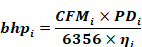
Where:
PDi = the pressure drop across the ith individual fan
bhpi = the input power of the ith individual fan
CFMi = the airflow rate of the ith fan at design conditions
ηi = the efficiency of the ith individual fan
The total input power for the entire fan system is the sum of the input power of each of the fans that operate at peak design conditions and is explained by the following equation:

Where:
bhpTotal = the total input power for the fan system
bhpi = the input power of the ith individual fan
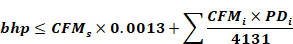
The maximum input power permitted by the standard is explained by the following equations for constant-volume and variable-volume systems. The first part of the equation denotes the basic allowance for input power. The second part of the equation denotes additional input power allowed for special filtration or devices listed in Table 4-21 . The additional power for these devices is based on the flow rate of air through the device, not the total supply air flow rate.
(Constant volume systems)
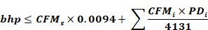
(Variable volume systems)
Where:
CFMs = the maximum design supply airflow rate to conditioned spaces served by the system in cubic feet per minute
PDi = the pressure drop across the ith individual fan
bhpi = the input power of the ith individual fan
CFMi = the airflow rate of the ith fan at design conditions
4.6.2.4 Pressure Drop Adjustment Devices
The types of devices listed in Table 4-22 that qualify for additional fan power are as follows:
1. Return or exhaust systems required by code or accreditation standards to be fully ducted, or systems required to maintain air pressure differentials between adjacent rooms. The basic input power allowance is based on the assumption that return air passes through an open plenum on its way back to the fan system. For systems where all of the return air is ducted back to the return, an additional pressure drop allowance of 0.5 inches of water is allowed. This credit may not be applied for air systems that have a mixture of ducted and non-ducted return.
2. Return and/or exhaust airflow control devices. Some types of spaces, such as laboratories, test rooms, and operating rooms, require that an airflow control device be provided at both the supply air delivery point and at the exhaust. The exhaust airflow control device is typically modulated to maintain a negative or positive space pressure relative to surrounding spaces. An additional pressure drop and associated input power adjustment are permitted when this type of device is installed. The credit may be taken when some spaces served by an air handler have exhaust airflow devices and other spaces do not. However, the credit is taken only for the cfm of air that is delivered to spaces with a qualifying exhaust airflow device.
3. Exhaust filters, scrubbers, or other exhaust treatment. Some applications require the air leaving the building be filtered to remove dust or contaminants. Exhaust air filters are also associated with some types of heat recovery systems, such as run-around coils. In this application, the purpose of the filters is to help keep the coils clean, which is necessary to maintain the effectiveness of the heat recovery system. When such devices are specified and installed, the pressure drop of the device at the fan system design condition may be included as a credit. When calculating the additional input power, only consider the volume of air that is passing through the device under fan system design conditions.
4. Particulate filtration credit: MERV 16 and greater and electronically enhanced filters. The primary purpose of filters is to keep the fans, coils, and ducts clean, and to reduce maintenance costs. A secondary purpose is to improve indoor air quality. MERV ratings are used as the basis of this credit. These ratings indicate the amount of particulate removed from the airstream. A higher MERV rating is more efficient and removes more material. The credit for filters with a MERV rating of 16 and greater and all electronically enhanced filters is based on two times the clean pressure drop of the filter at fan system design conditions. These clean pressure drop data are taken from manufacturers’ literature.
5. Carbon and other gas-phase air cleaners. For carbon and other gas-phase air cleaners, additional input power is based on the rated clean pressure drop of the air-cleaning device at fan system design conditions.
6. Biosafety cabinet. If the device is listed as a biosafety cabinet, you can use this credit.
7. Energy recovery device. Energy recovery devices exchange heat between the outside air intake stream and the exhaust airstream. There are two common types of heat recovery devices: heat wheels and air-to-air heat exchangers. Both increase the pressure drop and require a system with a larger input power. The fan power allowance for the energy recovery ventilator is determined by the equations in Option 2 and the adjustment factor from Table 4-22. The adjustment factor is a function of the enthalpy recovery ratio. This is intended to encourage designers to select energy recovery devices that have low pressure drops and high enthalpy recovery ratios, and thus provide a net energy reduction. This allows systems that have trouble meeting the fan power limit to gain a higher fan power allowance — by using larger energy recovery devices with higher enthalpy recovery ratios.
8. Coil runaround loop. The coil runaround loop is a form of energy recovery device that uses separate coils in the exhaust and outdoor air intakes with a pump in between. The credit is to account for the increased air pressure of these two coils.
9. Exhaust systems that serve fume hoods. Exhaust systems that serve fume hoods get an additional 0.35 inches of water credit to account for the pressure through the fume hood, ductwork, and zone valve or balancing devices. This credit applies to the exhaust fans only.
|
Device Credits |
Adjustment |
|
Return or exhaust systems required by code or accreditation standards to be fully ducted, or systems required to maintain air pressure differentials between adjacent rooms |
0.5 inches of water |
|
Return and/or exhaust airflow control devices |
0.5 inches of water |
|
Exhaust filters, scrubbers, or other exhaust treatment |
The pressure drop of device calculated at fan system design condition |
|
Particulate filtration credit: MERV 16 and greater and electronically enhanced filters |
Pressure drop calculated at two times the clean filter pressure drop at fan system design condition |
|
Carbon and other gas-phase air cleaners |
Clean filter pressure drop at fan system design condition |
|
Biosafety cabinet |
Pressure drop of device at fan system design condition |
|
Energy recovery device, other than coil runaround loop |
For each airstream [(2.2 x enthalpy recovery ratio) – 0.5] inches of water |
|
Coil runaround loop |
0.6 inches of water for each airstream |
|
Exhaust system serving fume hoods |
0.35 inches of water |
|
|
|
Example 4-45
Question
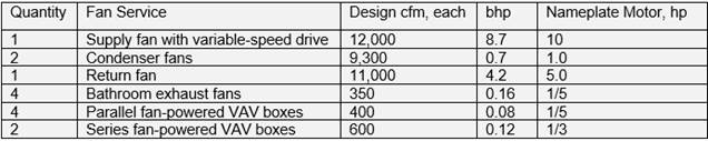
A VAV reheat system serves a low-rise office building. The building is served by one VAV packaged rooftop unit with a 10 hp supply fan with a VSD. Four parallel fan-powered VAV terminal units are used on north-facing perimeter offices for heating. Two series fan-powered VAV boxes, each with a third1/3 hp fan with an electronically commutated motor, serve two interior conference rooms.
The space also uses a local exhaust fan for each of the four bathrooms. Fans for the system are listed below. Fan performance is as described in the table below.
Is this system in compliance with Section 140.4(c)?
Answer
First, determine which fans to include in the nameplate fan system power calculation:
• The supply and return fans are clearly included in the fan power calculation.
• The condenser
fans are not included because they circulate outdoor air and do not affect the
conditioned air supplied to the space.
• The toilet exhaust fans are included because they exhaust from a conditioned space.
• The parallel fan-powered VAV boxes are not included in the fan power
calculation because they
operate in heating mode when the supply fan is not operating at design
conditions.
• The series fan-powered boxes run continuously and are included in the fan power calculation.
The total nameplate power is 15.7 bhp, as shown below.
Nameplate Power = 10 + 5 + (4 x 1/5) + (2 × 1/3 ) = 16.5 hp
The total supply air delivered from the air handler is 12,000 cfm, and the allowed nameplate power for a variable-air-volume system is 18 hp as shown below.
Nameplate Powermax = 12,000 × 0.0015 = 18.0 hp
The total nameplate power of 16.5 hp is less than the allowed 18.0 hp, so the fan system complies with the standard. If the nameplate power exceeded the allowable limit, the system input power can be checked for compliance
Example 4-46
Question
A conventional VAV system serves an office building. Fan performance is as described in the table below. Is the system in compliance with Section 140.4(c)?
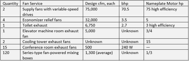
Answer
First, determine which fans to include in the fan power calculation:
• Supply fans are included.
• The economizer relief fans are not included because they will not operate at
peak cooling design
conditions. Had return fans been used, they would have to be included in the
calculation.
• The toilet exhaust fan is included because it exhausts conditioned air from
the building rather than
have it returned to the supply fan, and it operates at peak cooling
conditions.
• The elevator exhaust fan is not part of the system because it is assumed, in
this case, that
the
makeup air to
the elevator room is from the outdoors rather than from the building. Had makeup
air been transferred from the conditioned space, the fan would have been
included.
• The cooling tower fans operate at design conditions, but they also are not
part of the system
because they circulate only outdoor air. Although the cooling tower fan power
does not contribute
to the system fan power, it is required to meet the minimum efficiency
requirements in Table
110.2-G.
• The conference room exhaust fans are assumed to be transfer fans. They simply
exhaust air from
the room and discharge it to the ceiling plenum. Because this air is not exhausted to the outdoors,
the fans are not included.
• The series-type fan-powered VAV boxes are included because they assist in
supplying air to the
conditioned space and operate at design cooling conditions. If the boxes were
the parallel type,
they would not be included because they would not operate at design cooling
conditions.
Second, using Option 1, add up the nameplate power (not input power) of the eligible fans. For this example, the fans that are included and their motor power requirements are as follows:
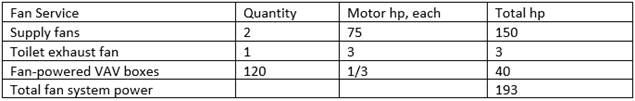
Third, determine the supply air rate. This is the total airflow rate supplied through the heating or cooling source, which in this case is equal to the total of the two supply fan airflow rates, 2 × 75,000 = 150,000 cfm. The supply rate is not the total of the fan-powered VAV box airflow rates; although this is the ultimate supply air rate to the conditioned space, this entire airflow does not flow through the heating or cooling source. The airflow rate from the exhaust fan is also not included in the supply air rate for the same reason.
Fourth, determine the criteria from Table 140.4-A. The series fan-powered VAV boxes supply a constant flow of air to the conditioned space, but the primary airflow, the airflow through the cooling source, varies as a function of load which meets the definition of a VAV system. Using Option 1, the maximum nameplate power for the system is 225 hp as shown below.
hp = CFMs × 0.0015
hp = 150,000 × 0.0015 = 225 hp
Fifth, compare the allowable fan system power with the proposed power. The actual fan system nameplate power of 193 hp is less than the 225 hp limit, so this system complies. If the system did not comply, the designer could consider using larger ducts to reduce static pressure or shifting to parallel fan-powered VAV boxes.
Example 4-47
Question
A hotel/motel building has floor-by-floor supply air-handling units but central toilet exhaust fans and minimum ventilation supply fans. How is the standard applied to this system?
Answer
Each air handler counts as a fan system. The energy of the central toilet exhaust and ventilation fans must be allocated to each air handler on a cfm-weighted basis. For instance, if one floor receives 2000 cfm of outdoor air, and the outdoor air fan supplies a total of 10,000 cfm with a 5 hp motor, 20 percent (2000/10,000 cfm) of the fan power (1 hp) is added to the fan power for the floor’s fan system. The airflow rates from the exhaust and ventilation fans must be included in the fan power calculation because these 140.4(c) requires to add exhaust fan power.
Example 4-48
Question
A wing of an elementary school building is served by eight water-source heat pumps, each equipped with a 3/4 hp fan motor and serving a single classroom. Ventilation air is supplied directly to each classroom by a dedicated outdoor-air system. Each classroom requires 500 cfm of outdoor air, so the system delivers the total of 4000 cfm of conditioned outdoor air using a 5 hp fan. Does this system need to comply with Section 140.4(c)?
Answer
Each water-source heat pump is a separate fan system because each has a separate cooling and heating source. The power of the dedicated outdoor-air system fan must be allocated to each heat pump on a cfm-weighted basis. For each classroom, 12.5 percent (500/4000 cfm) of the fan power (12.5 percent of 5 hp = 0.625 hp) is added to the fan power for the heat pump (0.75 + 0.625 = 1.375 hp). In this instance, even with the dedicated outdoor-air system fan allocated, each heat-pump fan system is less than the 5 hp threshold in Section 140.4(c), so the system does not need to comply with Section 140.4(c).
Example 4-49
Question
A variable-volume air handler serving a lab system has a fan system design supply airflow of 10,000 cfm. The supply fan has a 20 hp (nameplate) supply fan motor that operates at an input power of 13.9 bhp. The exhaust fan has a five hp motor that operates at an input power of 3.20 bhp. Flow control devices in the exhaust are used to maintain pressure relationships between spaces served by the system.
The air handler uses MERV 13 filters and exhaust air is completely ducted. The system uses outdoor air and has a run-around heat recovery system with coils in the supply and exhaust airstreams, each with 0.4 in. of water pressure drop at design airflow.
Does this fan system comply with the fan power requirements in Section 140.4(c)??
Answer
For this system, Option 2 is required in order to consider the additional pressure drop of the return air ducts, airflow control devices, and the heat recovery device. MERV 13 filters are required per Section 120.1(c)1B so no fan credit is awarded. From Table 140.4-A, the allowable system input power for the system is:
bhp = CFMs × 0.0013 + A
= 10,000 × 0.0013 + A = 13.0 + A
From Table 140.4-B, the pressure drop adjustment for the pressure drop adjustment for the fully ducted return (DR) is 0.5 in. of water, the pressure drop adjustment for the exhaust flow control device (FC) is 0.5 in. of water, and the pressure drop adjustment for a run-around loop heat recovery device is 0.6 in. of water per airstream. The airflow through all of these devices is 10,000 cfm, so the additional input power that is allowed is 5.33 bhp, as calculated below.
A = [ CFMDR × PDDR + CFMFC × PDFC + 2 × (CFMHX × PDHX) ] / 4,131
A = [ 10,000 × 0.5 + 10,000 × 0.5 + 2 × (10,000 × 0.6) ] / 4131 = 5.33 bhp
The total allowed input power is 13.0 bhp plus 5.33 bhp, or 18.3 bhp, which is greater than the fan system input power of 13.9 bhp plus 3.20 bhp, or 17.1 bhp. Therefore, the system meets the standard’s requirements.
4.6.2.5 Fractional HVAC Motors for Fans
HVAC fan motors that are one hp or less and 1/12 hp or greater shall be electronically-commutated motors or shall have a minimum motor efficiency of 70 percent when rated in accordance with the National Electric Manufacturers Assciation (NEMA) Standard MG 1-2006 at full-load rating conditions. These motors shall also have the means to adjust motor speed for either balancing or remote control. Belt-driven fans may use sheave adjustments for airflow balancing in lieu of a varying motor speed.
This requirement can be met with either electronically commutated motors or brushless direct current (DC) motors. These motors have higher efficiency than permanent split capacitor (PSC) motors and inherently have speed control that can be used for VAV operation or balancing.
This requirement includes fan-powered terminal units, fan-coil units, exhaust fans, transfer fans, and supply fans. There are three exceptions to this requirement:
1. Motors in fan-coil units and terminal units that operate only when providing heating to the space served. This includes parallel style fan-powered VAV boxes and heating only fan-coils.
2. Motors that are part of space conditioning equipment certified under §110.1 or §110.2. This includes supply fans, condenser fans, ventilation fans for boilers, and other fans that are part of equipment that is rated as a whole.
3. Motors that are part of space conditioning serving healthcare facilities.
4.6.2.6 Electric-Resistance Heating
The Energy Standards strongly discourage the use of electric-resistance space heat. Electric-resistance space heat is not allowed in the prescriptive approach except where:
1. Site-recovered or site-solar energy provides at least 60 percent of the annual heating energy requirements.
2. A heat pump is supplemented by an electric-resistance heating system, and the heating capacity of the heat pump is more than 75 percent of the design heating load at the design outdoor temperature (determined in accordance with the Energy Standards).
3. The total capacity of all electric-resistance heating systems serving the entire building is less than 10 percent of the total design output capacity of all heating equipment serving the entire building.
4. The total capacity of all electric-resistance heating systems serving the building, excluding those that supplement a heat pump, is no more than 3 kW.
5. An electric-resistance heating system serves an entire building that:
a. Is not a high-rise residential or hotel/motel building.
b. Has a conditioned floor area no greater than 5,000 sq ft.
c. Has no mechanical cooling.
d. Is in an area where natural gas is not currently available and an extension of a natural gas system is impractical, as determined by the natural gas utility.
6. The existing mechanical systems use electric reheat (when adding VAV boxes) added capacity cannot exceed 20 percent of the existing installed electric capacity, under any one permit application in an alteration.
7. The existing VAV system with electric reheat is being expanded, the added capacity cannot exceed 50 percent of the existing installed electric reheat capacity under any one permit in an addition.
8. Heating systems serve as emergency backup to gas heating equipment.
The Energy Standards allow a small amount of electric-resistance heat to be used for local space heating or reheating (provided reheat is in accordance with these regulations).
Example 4-50
Question
If a heat pump is used to condition a building having a design heating load of 100,000 Btu/h at 35 degrees F, what are the sizing requirements for the compressor and heating coils?
Answer
The compressor must be sized to provide at least 75 percent of the heating load at the design heating conditions, or 75,000 Btu/h at 35 degrees F. The Energy Standards do not address the size of the resistance heating coils. Normally, they will be sized based on heating requirements during defrost.
4.6.2.7 Cooling Tower Flow Turndown
The Energy Standards require that open cooling towers with multiple condenser water pumps be designed so that all cells can be run in parallel with the larger of the flow that is produced by the smallest pump or50 percent of the design flow for the cell.
In a large plant at low load operation, not all the cells are typically run at once. This is allowed in the Energy Standards.
Cooling towers are very efficient at unloading the fan energy drops off as the cube of the airflow. It is always more efficient to run the water through as many cells as possible- two fans at half speed use less than one third of the energy of one fan at full speed for the same load. Unfortunately, there is a limitation with flow on towers. The flow must be sufficient to provide full coverage of the fill. If the nozzles do not fully wet the fill, air will go through the dry spots providing no cooling benefit and cause the water at the edge of the dry spot to flash evaporate, depositing dissolved solids on the fill.
Fortunately, the cooling tower manufacturers do offer low-flow nozzles (and weirs on basin type towers) to provide better flow turndown. This typically only costs $100 to $150 per tower cell. As low-flow nozzles can eliminate the need for a tower isolation control point, this option provides energy savings at a reduced first cost.
Example 4-51
Question
If a large central plant has five equally sized chillers and five equally sized cooling tower cells do all of the cooling tower cells need to operate when only one chiller is on-line?
Answer
No. You would probably only run three cells with one chiller. The cooling tower cells must be designed to run at 33 percent of their nominal design flow. With two to five chillers running, you would run all of the cells of the cooling tower. With only one chiller running you would run three cells. In each case, you would need to keep the tower flow above the minimum that it was designed for.
Centrifugal Fan Limitation
Open cooling towers with a combined rated capacity of 900 gpm and greater are prohibited from using centrifugal fans. The 95 degree F condenser water return, 85 degree F condenser water supply and 75 degree F outdoor wet-bulb temperature are test conditions for determining the rated flow capacity in gpm. Centrifugal fans use approximately twice the energy as propeller fans for the same duty. There are a couple of exceptions to this requirement:
1. Cooling towers that are ducted (inlet or discharge) or have an external sound trap that requires external static pressure capability.
2. Cooling towers that meet the energy efficiency requirement for propeller fan towers in Table 4-7.
Centrifugal fans may be used on closed circuit fluid coolers.
As with all prescriptive requirements centrifugal fan cooling towers may be used when complying with the performance method. The budget building will be modeled using propeller towers.
Cooling Tower Efficiency
Prescriptively, axial fan open-circuit cooling towers with a combined rated capacity of 900 gpm or greater must achieve a rated efficiency no less than 60 gpm/hp. This efficiency is rated at specific temperature conditions which are 95 degree F condenser water return; 85 degree F condenser water supply; and 75 degree F outdoor wet-bulb temperature as listed in Table 4-7. There are a couple of exceptions to this requirement:
1. Cooling towers which are installed as a replacement to an existing chilled water plant, if the tower is located on an existing roof or inside an existing building.
2. Cooling towers that are serving buildings in Climate Zones 1 or 16.
As with all prescriptive requirements, axial-fan open-circuit cooling towers with a capacity of 900 gpm or larger and less than 60 gpm/hp may be used when complying with the performance method. The towers must still comply with the mandatory minimum efficiency rating of 42.1 gpm/hp as listed in Table 4-7 Chiller Efficiency
In Table 4-4, there are two sets of efficiency for almost every size and type of chiller. Path A represents fixed speed compressors and Path B represents variable speed compressors. For each path, there are two efficiency requirements: a full load efficiency and an integrated part-load efficiency. Path A typically has a higher full load efficiency and a lower part-load efficiency than Path B. In all California climates, the cooling load varies enough to justify the added cost for a Path B chiller. This is a prescriptive requirement so Path B is used in the base case model in the performance method.
There are a number of exceptions provided to this requirement:
1. Chillers with an electrical service of greater than 600 volts. This is due to the fact that the cost of a VSD is much higher on medium voltage service.
2. Chillers attached to a heat recovery system with a design heat recovery capacity greater than 40 percent of the chiller's design cooling capacity. Heat recovery typically requires operation at higher lifts and compressor speeds.
3. Chillers used to charge thermal energy storage systems with a charging temperature of less than 40 degrees F. This again requires a high lift operation for chillers.
4. In a building with more than three chillers only three are required to meet the Path B efficiencies.
4.6.2.8 Limitation on Air Cooled Chillers
New central cooling plants and cooling plant expansions will be limited on the use of air-cooled chillers. For both types the limit is 300 tons per plant.
In the studies provided to support this requirement, air cooled chillers always provided a higher life cycle cost than water-cooled chillers even accounting for the water and chemical treatment costs.
Exceptions to this requirement:
1. Where the water quality at the building site fails to meet manufacturer’s specifications for the use of water-cooled chillers.
This exception recognizes that some parts of the state have exceptionally high quantities of dissolved solids that could foul systems or cause excessive chemical treatment or blow down.
2. Chillers that are used to charge a thermal energy storage system with a design temperature of less than 40 degrees F.
This addresses the fact that air-cooled chillers can operate very efficiently at low ambient air temperatures. Since thermal energy storage systems operate for long hours at night, these systems may be as efficient as a water-cooled plant. The chiller must be provided with head pressure controls to achieve these savings.
3. Air cooled chillers with minimum efficiencies approved by the Energy Commission pursuant to §10-109(d).
This exception was provided in the event that an exceptionally high efficiency air cooled chiller was developed. None of the high-efficiency air-cooled chillers currently evaluated are as efficient as water-cooled systems using the lowest chiller efficiency allowed by §110.2.
4. Systems serving healthcare facilities.
4.6.2.9 Exhaust System Transfer Air
The standard prescriptively requires the use of transfer air for exhaust air makeup in most cases. The purpose is to avoid supply air that requires increased outdoor air intake, which would require conditioning, for exhaust makeup when return or relief air from neighboring spaces can be used instead. The requirement limits the supply of conditioned air to not exceed the larger of: 1.) the supply flow required for space heating or space cooling, 2.) the required ventilation rate, or 3.) the exhaust flow, minus the available transfer air from conditioned spaces or plenums on the same floor and within 15 ft and not in different smoke or fire compartments. Available transfer air does not include air required to maintain pressurization and air that cannot be transferred based on air class as defined by in §120.1.
There are a few exceptions to this requirement:
1. Biosafety laboratories classified Level 3 or higher
2. Vivarium spaces
3. Spaces that are required by applicable codes and standards to be maintained at positive pressure relative to adjacent spaces. For spaces taking this exception, any transferable air that is not directly transferred shall be made available to the associated air-handling unit and shall be used whenever economizer or other options do not save more energy.
4. Spaces where the demand for transfer air may exceed the available transfer airflow rate and where the spaces have a required negative pressure relationship. For spaces taking this exception, any transferable air that is not directly transferred shall be made available to the associated air-handling unit and shall be used whenever economizer or other options do not save more energy.
A compliant example would be a space with a restroom with 300 cfm of exhaust. The makeup air would consist of 60 cfm of supply air and 240 cfm of transfer air from an adjacent ceiling return air plenum. The amount of air required for the space is 60 cfm for heating and cooling and the rest of the makeup air is transferred from the return air plenum.
A non-compliant example would be if the same space had a constant air volume box with reheat supplying all of the makeup air. The reheat would be needed to prevent the space from being overcooled. Since there is transfer air available in the adjacent plenum, the maximum allowed supply air would be only what’s required for space heating or cooling, which would be 60 cfm.