This section covers controls that are mandatory for all system types, including:
•Heat pump controls for the auxiliary heaters
•Zone thermostatic control including special requirements for hotel/motel guest rooms and perimeter systems
•Shut-off and setback/setup controls
•Infiltration control
•Off-hours space isolation
•Economizer fault detection and diagnostics (FDD)
•Control equipment certification
•Direct digital controls (DDC)
•Optimum start/stop controls.
4.5.1.1 Zone Thermostatic Controls
Thermostatic controls must be provided for each space-conditioning zone or dwelling unit to control the supply of heating and cooling energy within that zone. The controls must have the following characteristics:
1. When used to control heating, the thermostatic control must be adjustable down to 55 degrees F or lower.
2. When used to control cooling, the thermostatic control must be adjustable up to 85 degrees F or higher.
3. When used to control both heating and cooling, the thermostatic control must be adjustable from 55 degrees F to 85 degrees F and also provide a temperature range or dead band of at least 5 degrees F. When the space temperature is within the dead band, heating and cooling energy must be shut off or reduced to a minimum. A dead band is not required if the thermostat requires a manual changeover between the heating and cooling modes Exception to §120.2(b)3.
4. For all single zone, air conditioners and heat pumps all thermostats shall have setback capabilities with a minimum of four separate set points per 24-hour period. Also the thermostat must comply with the occupant controlled smart thermostat requirements in §110.12(a), which is capable of responding to demand response signals in the event of grid congestion and shortages during high electrical demand periods.
5. Systems equipped with DDC to the zone level, rather than zone thermostats, must be equipped with automatic demand shed controls that provide demand shedding, as described later in Section 4.5.1.7.
The set point may be adjustable either locally or remotely, by continuous adjustment or by selection of sensors.
Figure 4-13: Proportional Control Zone Thermostat
Supplemental perimeter heating or cooling systems are sometimes used to augment a space-conditioning system serving both interior and perimeter zones. This is allowed provided controls are incorporated to prevent the two systems from conflicting with each other. If that were the case, then the Energy Standards require that:
1. The perimeter system must be designed solely to offset envelope heat losses or gains.
2. The perimeter system must have at least one thermostatic control for each building orientation of 50 ft or more.
3. The perimeter system is controlled by at least one thermostat located in one of the zones served by the system.
The intent is that all major exposures are controlled by their own thermostat, and that the thermostat is located within the conditioned perimeter zone. Other temperature controls, such as outdoor temperature reset or solar compensated outdoor reset, do not meet these requirements of the Energy Standards.
Example 4-23
Question
Can an energy management system be used to control the space temperatures?
Answer
Yes, provided the space temperature set points can be adjusted, either locally or remotely. This section sets requirements for “thermostatic controls” which need not be a single device like a thermostat; the control system can be a broader system like a DDC system. Some DDC systems employ a single cooling set point and a fixed or adjustable deadband. These systems comply if the deadband is adjustable or fixed at 5 degrees F or greater.
Thermostats with adjustable set points and deadband capability are not required for zones that must have constant temperatures to prevent the degradation of materials, an exempt process, or plants or animals (Exception 1 to §120.2(b)4). Included in this category are manufacturing facilities, hospital patient rooms, museums, and computer rooms. Chapter 13 describes mandated acceptance test requirements for thermostat control for packaged HVAC systems.
4.5.1.2 Hotel/Motel Guest Rooms and High-Rise Residential Dwellings Thermostats
The Energy Standards require that thermostats in hotel/motel guest rooms have:
1. Numeric temperature set points in degrees F and degrees Celsius,
2. Set point stops that prevent the thermostat from being adjusted outside the normal comfort range (± 5 degree F or ± 3 degree Celsius). These stops must be concealed so that they are accessible only to authorized personnel.
3. Setback capabilities with a minimum of four separate set points per 24 hour period
Example 4-24
Question
What is the perimeter zoning required for the building shown here?

Answer
The southeast and northwest exposures must each have at least one perimeter system control zone, since they are more than 50 ft in length. The southwest exposure and the serrated east exposure do not face one direction for more than 50 continuous ft in length. They are therefore “minor” exposures and need not be served by separate perimeter system zones, but may be served from either of the adjacent zones.
Example 4-25
Question
Pneumatic thermostats are proposed for zone control. However, the model specified cannot be adjusted to meet the range required by §120.2(a) to (c). How can this system comply?
Answer
§120.2(a) to (c) applies to “thermostatic controls” which can be a system of thermostats or control devices, not necessarily a single device. In this case, the requirement could be met by using multiple thermostats. The pneumatic thermostats could be used for zone control during occupied hours and need only have a range consistent with occupied temperatures (e.g. 68 degrees F to 78 degrees F), while two additional electric thermostats could be provided, one for setback control (adjustable down to 55 degrees F) and one for set-up (adjustable up to 85 degrees F). These auxiliary thermostats would be wired to temporarily override the system to maintain the setback/setup set points during off-hours.
4.5.1.3 Heat-Pump Controls
Heat pumps with electric resistance supplemental heaters must have controls that limit the operation of the supplemental heater to defrost and as a second stage of heating when the heat pump alone cannot satisfy the load. The most effective solution is to specify an electronic thermostat designed specifically for use with heat pumps. This “anticipatory” thermostat can detect if the heat pump is raising the space temperature during warm-up fast enough to warrant locking out the auxiliary electric resistance heater.
This requirement can also be met using conventional electronic controls with a two-stage thermostat and an outdoor lockout thermostat wired in series with the auxiliary heater. The outdoor thermostat must be set to a temperature where the heat pump capacity is sufficient to warm up the space in a reasonable time (e.g., above 40 degrees F). This conventional control system is depicted schematically below in Figure 4-14.
Figure 4-14: Heat Pump Auxiliary Heat Control, Two-Stage and Outdoor Air Thermostats

4.5.1.4 Shut Off and Temperature Setup/Setback
§120.2(e)1,2 and 3
For specific occupancies and conditions, each space-conditioning system must be provided with controls that comply with the following requirements:
A. The control can automatically shut off the equipment during unoccupied hours and shall have one of the following:
1. An automatic time switch device with the same characteristics that lighting devices must have, as described in Chapter 5, and a manual override accessible to the occupants that allows the system to operate up to four hours. The manual override can be included as a part of the control device, or as a separate override control.
2. An occupancy sensor. Since a building ventilation purge is required prior to normal occupancy, an occupancy sensor may be used to control the availability of heating and cooling, but should not be used to control the outdoor ventilation system.
3. A four-hour timer that can be manually operated to start the system. As with occupancy sensors, the same restrictions apply to controlling outdoor air ventilation systems.
Exception to §120.2(e)1: The mechanical system serving retail stores and associated malls, restaurants, grocery stores, churches, or theaters equipped with seven-day programmable timers do not have to comply with the above requirements.
B. When shut down, the controls shall automatically restart the system to maintain:
1. A setback heating thermostat set point, if the system provides mechanical heating. Exception: Thermostat setback controls are not required in nonresidential buildings in areas where the Winter Median of Extremes outdoor air temperature is greater than 32 degrees F.
2. A setup cooling thermostat set point, if the system provides mechanical cooling. Exception: Thermostat setup controls are not required in nonresidential buildings in areas where the summer design dry Bulb 0.5 percent temperature is less than 100 degrees F.
C. Occupant sensing zone controls
Space conditioning systems serving rooms that are required to have occupant sensing controls to satisfy the lighting control requirements of Section 130.1(c) and where Table 4-12 identifies the room or space is eligible to reduce the ventilation air to zero, shall incorporate this control strategy known as occupied standby mode. The room, space or zone is considered to be in occupied standby mode when all the rooms within the zone are unoccupied for more than five minutes. When a zone is in occupied standby mode, the cooling set point shall be increased by at least 2 degrees F and the heating set point shall be decreased by at least 2 degrees F, or for a multiple zone system with DDC to the zone level the cooling set point shall be increased by at least 0.5 degrees F and the heating set point shall be decreased by at least 0.2 degrees F. All airflow to the zone shall be shut off when in occupied standby mode. If the temperature in the zone drifts outside the deadband, then the full space conditioning system will turn on to satisfy the load in that zone.
This occupancy control must not prevent outside air ventilation of the space when the pre-occupancy ventilation purge cycle is required by §120.1(d)2. Pre-occupancy purge ventilates the space prior to scheduled occupancy each day to dilute and exhaust contaminants that have built up inside the building over night while the HVAC systems were off. Typically, the space is unoccupied during these periods and the occupancy control must not disable this scheduled ventilation cycle.
D. Exceptions for automatic shut off, setback and setup, and occupant sensor setback:
1. Exception to A, B, and C: It can be demonstrated to the satisfaction of the enforcement agency that the system serves an area that must operate continuously.
2. Exception to A, B, and C: Systems have a full load demand of 2 kW or less, or 6,826 Btu/h, if they have a readily accessible manual shut off switch. Included is the energy consumed within all associated space-conditioning systems including compressors, as well as the energy consumed by any boilers or chillers that are part of the system.
3. Exception to A and B: Systems serve hotel/motel guest rooms, if they have a readily accessible manual shut-off switch.
E. Hotel/motel guest room controls:
Hotel/motel guest rooms shall have captive card key controls, occupancy sensing controls, or automatic controls such that within 30 minutes of a guest leaving the room, set points are set-up of at least +5 degrees F (+3 degrees Celsius) in cooling mode and set-down of at least -5 degrees F (-3 degrees Celsius) in heating mode.
Example 4-26
Question
Can occupancy sensors be used in an office to shut off the VAV boxes during periods when the spaces are unoccupied?
Answer
Yes, only if the ventilation is provided through operable openings. With a mechanical ventilation design the occupancy sensor could be used to reduce the VAV box airflow to the minimum allowed for ventilation. It should not shut the airflow off completely; ventilation must be supplied to each space at all times when the space is usually occupied.
Example 4-27
Question
Must a 48,000 sq ft building with 35 fan coil units have 35 time switches?
Answer
No. More than one space-conditioning system may be grouped on a single time switch, subject to the area limitations required by the isolation requirements (see Isolation). In this case, the building would need two isolation zones, each no larger than 25,000 sq ft, and each having its own time switch.
Example 4-28
Question
Can a thermostat with set points determined by sensors (such as a bi-metal sensor encased in a bulb) be used to accomplish a night setback?
Answer
Yes. The thermostat must have two heating sensors, one each for the occupied and unoccupied temperatures. The controls must allow the setback sensor to override the system shutdown.
Figure 4-15: Shut-Off and Setback Controls Flowchart

These provisions are required by the Energy Standards to reduce the likelihood that shut-off controls will be circumvented to cause equipment to operate continuously during unoccupied hours.
Example 4-29
Question
If a building has a system comprised of 30 fan coil units, each with a 300-watt fan, a 500,000 Btu/h boiler, and a 30-ton chiller, can an automatic time switch be used to control only the boiler and chiller (fan coils operate continuously)?
Answer
No. The 2 kW criteria applies to the system as a whole, and is not applied to each component independently. While each fan coil only draws 300 W, they are served by a boiler and chiller that draw much more. The consumption for the system is well in excess of 2 kW.
Assuming the units serve a total area of less than 25,000 sq ft (see Isolation), one-time switch may control the entire system.
4.5.1.5 Infiltration Control
Outdoor air supply and exhaust equipment must incorporate dampers that automatically close when fans shut down.
Fans shut down when ventilation or conditioned air is not necessary for the building, which only occurs when a normally scheduled unoccupied period begins (such as overnight or a weekend for office buildings) or when occupancy sensors are used for ventilation control. The dampers may either be motorized, or of the gravity type. However only motorized dampers that remain closed when the fan turns on would be capable of accomplishing the best practice below.
|
Best Practice Though the Energy Standards only specify fan shut down, as a best practice outside air dampers should also remain completely closed during the unoccupied periods, even when the fan turns on to provide setback heating or cooling. However, to avoid instances of insufficient ventilation, or sick building syndrome, the designer should specify that the outside air dampers open and provide ventilation if: o The unoccupied period is a one-hour pre-occupancy purge ventilation, as per §120.1(c)2. o The damper is enabled by an occupant sensor in the building as per §120.1(c)5, indicating that there are occupants that demand ventilation air. o The damper is enabled by an override signal as per §120.2(e)1, which includes an occupancy sensor but also an automatic time switch control device or manually operated four-hour timer.
|
Exception 1: Equipment that serves an area that must operate continuously.
Exception 2: Damper control required on gravity ventilators or other non-electrical equipment, provided that readily accessible manual controls are incorporated.
Exceptions 3 and 4: Damper control is not required at combustion air intakes and shaft vents, or where prohibited by other provisions of law. If the designer elects to install dampers or shaft vents to help control stack-induced infiltration, the damper should be motorized and controlled to open in a fire in accordance with applicable fire codes.
4.5.1.6 Isolation Area Controls
Large space-conditioning systems serving multiple zones may waste considerable quantities of energy by conditioning all zones when only a few are occupied. Typically, this occurs during evenings or weekends when less people are working. When the total area served by a system exceeds 25,000 sq ft, the Energy Standards require that the system be designed, installed and controlled with area isolation devices to minimize energy consumption during these times. The requirements are:
1. The building shall be divided into isolation areas, the area of each not exceeding 25,000 sq ft. An isolation area may consist of one or more zones.
2. An isolation area cannot include spaces on different floors.
3. Each isolation area shall be provided with isolation devices such as valves or dampers that allow the supply of heating or cooling to be setback or shut off independently of other isolation areas.
4. Each isolation area shall be controlled with an automatic time switch, occupancy sensor, or manual timer. The requirements for these shut-off devices are the same as described previously in 4.5.1.4. As discussed previously for occupancy sensors, a building purge must be incorporated into the control sequences for normally occupied spaces, so occupancy sensors and manual timers are best limited to use in those areas that are intermittently occupied.
Any zones requiring continuous operation do not have to be included in an isolation area.
Example 4-30
Question
How many isolation zones does a 55,000 sq ft building require?
Answer
At least three. Each isolation zone may not exceed 25,000 sq ft.
A. Isolation of Zonal Systems
Small zonal type systems such as water loop heat pumps or fan coils may be grouped on automatic time-switch devices, with control interlocks that start the central plant equipment whenever any isolation area is occupied. The isolation requirements apply to equipment supplying heating and cooling only; central ventilation systems serving zonal type systems do not require these devices.
Isolation of Central Air Systems
Figure 4-16 below depicts four methods of area isolation with a central VAV system:
1. On the lowest floor, programmable DDC boxes can be switched on a separate time schedule for each zone or blocks of zones. When unoccupied, the boxes can be programmed to have zero minimum volume set points and unoccupied setback/setup set points. This form of isolation can be used for sections of a single floor distribution system.
2. On the second floor, normally closed pneumatic or electric VAV boxes are used to isolate zones or groups of zones. In this scheme the control source (pneumatic air or control power) for each group is switched on a separate control signal from an individual time schedule. Again, this form of isolation can be used for sections of a single floor distribution system.
3. On the third floor, isolation is achieved by inserting a single motorized damper on the trunk of the distribution ductwork. With the code requirement for fire/smoke dampers (see next numbered item) this method is somewhat obsolete. When applied, this method can only control a single trunk duct. Care must be taken to integrate the motorized damper controls into the fire/life safety system.
4. On the top floor, a combination fire smoke damper is controlled to provide the isolation. This control can only be used on a single trunk duct. Fire/smoke dampers required by code can be used for isolation at virtually no cost, provided that they are wired so that the fire life-safety controls take precedence over off-hour controls (local fire officials generally allow this dual usage of smoke dampers since it increases the likelihood that the dampers will be in good working order in the event of a fire). No isolation devices are required on the return.
Figure 4-16: Isolation Methods for a Central VAV System

Example 4-31
Question
Does each isolation area require a ventilation purge?
Answer
Yes. Consider each isolation area as if it were a separate air-handling system, each with its own time schedule, setback and setup control.
Turndown of Central Equipment
Where isolation areas are provided, it is critical that the designer plans the central systems (fans, pumps, boilers and chillers) to have sufficient stages of capacity or turndown controls to operate stably, as required to serve the smallest isolation area on the system. Failure to do so may cause fans to operate in surge, excessive equipment cycling and loss of temperature control. Schemes include:
1. Application of demand based supply pressure reset for VAV fan systems. This will generally keep variable speed driven fans out of surge and can provide 10:1 turndown.
2. Use of pony chillers, an additional small chiller to be used at partial load conditions, or unevenly split capacities in chilled water plants. This may be required anyway to serve 24/7 loads.
3. Unevenly split boiler plants.
4.5.1.7 Automatic Demand Shed Controls
HVAC systems with DDC to the zone level must be programmed to allow centralized demand shed for non-critical zones as follows:
1. The controls shall have the capability to remotely increase the operating cooling temperature set points by four degrees or more in all non-critical zones, via signal from a centralized contact or software point within an EMCS.
2. The controls shall have the capability to remotely decrease the operating heating temperature set points by four degrees or more in all non-critical zones, via signal from a centralized contact or software point within an EMCS.
3. The controls shall have the capability to remotely reset the temperatures in all non-critical zones to original operating levels, via signal from a centralized contact or software point within an EMCS.
4. The controls shall be programmed to provide an adjustable rate of change for the temperature increase, decrease, and reset.
5. The controls shall have the following features:
a. The ability to be disabled by authorized facility operators.
b. Controlled manually by authorized facility operators to allow adjustment of heating and cooling set points globally from a single point in the EMCS.
c. Upon receipt of a demand response signal, the space-conditioning systems shall automatically conduct a centralized demand shed (as specified in one and two above) for non-critical zones during the demand response period.
The Energy Standards defines a critical zone as a zone serving a process where reset of the zone temperature set point during a demand shed event might disrupt the process, including but not limited to data centers, telecom/private branch exchange rooms, and laboratories.
To comply with this requirement, each non-critical zone temperature-control loop will need a switch that adds in an offset on the cooling temperature set point from a central demand shed signal. A rate of change limiter can either be built into the zone control or into the functional block for the central offset value. The central demand shed signal can be activated either through a global software point or a hardwired digital contact.
This requirement is enhanced with an acceptance test to ensure that the system was programmed as required.
4.5.1.8 Economizer Fault Detection and Diagnostics
Economizer Fault Detection and Diagnostics (FDD) is a mandatory requirement for all newly installed air handlers with a mechanical cooling capacity greater than 54,000 Btu/hr and an air economizer.
The FDD system can be either a stand-alone unit or integrated. A stand-alone FDD unit is added onto the air handler, while an integrated FDD system is included in the air handler system controller or is part of the DDC system.
Where required, the FDD system shall meet each of the following requirements:
1. Temperature sensors shall be permanently installed to monitor system operation of outside air, supply air, and return air.
2. Temperature sensors shall have an accuracy of ±2 degrees F over the range of 40 degrees F to 80 degrees F.
3. The controller shall have the capability of displaying the value of each sensor.
4. The controller shall provide system status by indicating the following conditions:
a. Free cooling available.
b. Economizer enabled.
c. Compressor enabled. For systems that don’t have compressors, indicating “mechanical cooling enabled” also complies.
d. Heating enabled, if the system is capable of heating.
e. Mixed air low limit cycle active.
5. The unit controller shall allow manual initiation of each operating mode so that the operation of cooling systems, economizers, fans, and heating system can be independently tested and verified.
6. Faults shall be reported using one of the following options:
a. An EMCS that is regularly monitored by facility personnel
b. Displayed locally on one or more zone thermostats or a device within five feet of a zone thermostat, clearly visible, at eye level and meet the following requirements:
i. On the thermostat, device, or an adjacent written sign, there must be instructions displayed for how to contact the appropriate building personnel or an HVAC technician to service the fault.
ii. In buildings with multiple tenants, the fault notification shall either be within property management offices or in a common space accessible by the property or building manager.
c. Reported to a fault management application that automatically provides notification of the fault to a remote HVAC service provider. This allows the service provider to coordinate with an HVAC technician to service the fault.
7. The FDD system shall have the minimum capability of detecting the following faults:
a. Air temperature sensor failure/fault. This failure mode is a malfunctioning air temperature sensor, such as the outside air, discharge air, or return air. This could include loss of calibration, complete failure (either through damage to the sensor or its wiring) or failure due to disconnected wiring.
b. Not economizing when it should, meaning when programmed to do so. In this case, the economizer should be enabled yet is not providing free cooling. This leads to an unnecessary increase in mechanical cooling energy. For example, if the economizer high limit set point is too low (55˚F), or the economizer is stuck in the closed position.
c. Economizing when it should not, meaning when not programmed to do so. This is the opposite malfunction from the previous problem . In this case, conditions are such that the economizer should be at minimum ventilation position, but instead is open beyond the correct position. This leads to an unnecessary increase in heating and cooling energy. For example, if the economizer high limit set point is too high (82˚F), or the economizer is stuck in the open position.
d. Damper not modulating. This issue represents a stuck, disconnected, or otherwise inoperable damper that does not modulate open and closed. It is a combination of the previous two faults: not economizing when programmed to do so, and economizing unnecessarily.
e. Excess outdoor air. This failure occurs when the economizer provides an excessive level of ventilation, usually much higher than is needed for design minimum ventilation. It causes an energy penalty during periods when the economizer should not be enabled(during cooling mode when outdoor conditions are higher than the economizer high limit set point). During heating mode, excess outdoor air will increase heating energy.
8. The FDD system shall be certified to the Energy Commission, by the manufacturer of the FDD system, to meet the requirements one through seven, above. The manufacturer submittal package is available in Joint Appendices JA6.3 Economizer Fault Detection and Diagnostics Certification Submittal Requirements.
For air handlers controlled by DDC (including packaged systems), FDD sequences of operations must be developed to adhere with the requirements of §120.2(i)1 through 7. FDD systems controlled by DDC are not required to be certified to the Energy Commission, but manufacturers, controls suppliers, or other market actors can choose to apply for certification. For DDC based FDD systems, a new acceptance test has been developed to test the sequences of operations in the field to verify that they in-fact comply with the required faults of §120.1(i).
Although not required by the Energy Standards, ASHRAE Guideline 36-2017 is a good reference for developing sequences of operations specifically for the faults listed in 120.2(i). The purpose of Guideline 36 is to provide uniform sequences of operation for heating, ventilating, and air-conditioning (HVAC) systems that are intended to maximize HVAC system energy efficiency and performance, provide control stability, and allow for real-time fault detection and diagnostics. To properly adhere to Guideline 36, all sequences of operations design elements in Sections 5.16.14 and/or 5.18.13 of that guideline must be implemented, including defining operating states, the use of an alarm delay, and the installation of an averaging mixed air temperature sensor. If a designer uses Guideline 36 to detect the required economizer faults in Title 24 Section 120.2(i), the sequences of operations should include Guideline 36 Fault Conditions numbers #2, 3, and 5 through 13, at a minimum. Other Title 24 FDD requirements in Section 120.2(i) and acceptance tests are not met by including these fault conditions into sequences of operations, and must be met through other means.
4.5.1.9 Direct Digital Controls
The requirement for DDC will mostly impact smaller buildings, since it is already common practice to install DDC in medium and large buildings; primarily due to the size and complexity of HVAC systems of medium and large buildings, which DDC is well suited to operate. Small buildings in the past did not require DDC and therefore could not take advantage of basic energy savings strategies.
DDC systems facilitate energy saving measures through monitoring and regulating the HVAC systems and optimizing their efficient operation. With most buildings requiring DDC, the following energy saving measures will be triggered if DDC is to the zone level:
1. DCV (mandatory) - Section 4.3.9
2. Automatic Demand Shed Controls (mandatory) - Section 4.5.1.7
3. Optimum Start/Stop Controls (mandatory) – Section 4.5.1.9
4. Set point Reset Controls for VAV systems (prescriptive) - Section 4.5.2.3
For further explanation, see the appropriate compliance manual sections for the measures listed above.
The Energy Standards mandate DDC for only certain building applications with minimum qualifications or equipment capacities, as specified in Table 120.2-A of the Energy Standards, see Table 4-5 below for a duplicate of this table.
|
BUILDING STATUS |
APPLICATIONS |
QUALIFICATIONS |
|
Newly Constructed Buildings |
Air handling system and all zones served by the system |
Individual systems supplying more than three zones and with design heating or cooling capacity of 300 kBtu/h and larger |
|
Newly Constructed Buildings |
Chilled water plant and all coils and terminal units served by the system |
Individual plants supplying more than three zones and with design cooling capacity of 300 kBtu/h (87.9 kW) and larger |
|
Newly Constructed Buildings |
Hot water plant and all coils and terminal units served by the system |
Individual plants supplying more than three zones and with design heating capacity of 300 kBtu/h (87.9 kW) and larger |
|
Additions or Alterations |
Zone terminal unit such as VAV box |
Where existing zones served by the same air handling, chilled water, or hot water systems that have DDC |
|
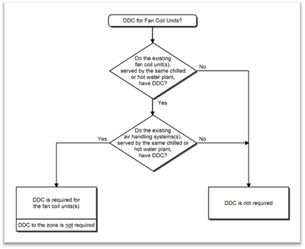
Additions or Alterations |
Air handling system or fan coil |
Where existing air handling system(s) and fan coil(s) served by the same chilled or hot water plant have DDC |
|
Additions or Alterations |
New air handling system and all new zones served by the system |
Individual systems with design heating or cooling capacity of 300 kBtu/h and larger and supplying more than three zones and more than 75 percent of zones are new |
|
Additions or Alterations |
New or upgraded chilled water plant |
Where all chillers are new and plant design cooling capacity is 300 kBtu/h (87.9 kW) and larger |
|
Additions or Alterations |
New or upgraded hot water plant |
Where all boilers are new and plant design heating capacity is 300 kBtu/h (87.9 kW) and larger |
Source: California Energy Commission, Building Energy Efficiency Standards, Table 120.2-A
Buildings that do not meet the specified minimum qualifications are not required to install DDC.
Follow the flowchart in Figure 4-17 to determine if a DDC system is required for newly constructed buildings, additions, or alterations. The Building Status Flowchart will indicate which equipment flowchart (
Figure 4-18 through Figure 4-22) should be used for each type of HVAC equipment that will be installed in the building.
The flowcharts will indicate whether DDC is required for the building, how it should be applied to the equipment and whether it is required to be installed to the zone level.
Figure 4-17: Building Status Flowchart

Figure 4-18: Chilled Water Plant Flowchart
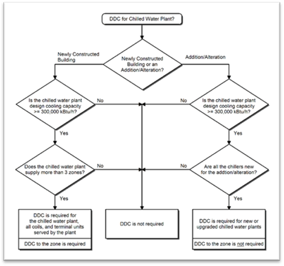
Figure 4-19: Hot Water Plant Flowchart
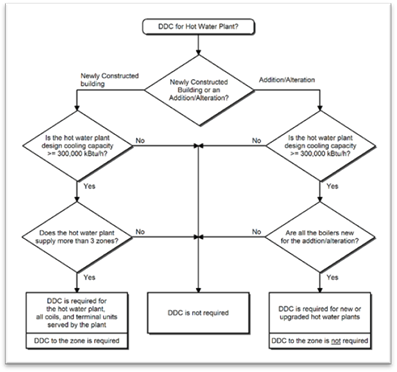
Figure 4-20: Air Handling System Flowchart
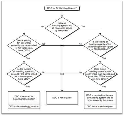
Figure 4-21: Zone Terminal Unit Flowchart
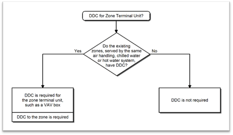
Figure 4-22: Fan Coil Units Flowchart
For additions or alterations to buildings, zones that are not part of the addition or alteration are not required to be retrofitted with DDC to the zone. Pre-existing DDC systems in buildings are not required to be retrofitted so DDC is to the zone.
Example 4-32
Question
If a newly constructed building has a HVAC system comprised of an air handling system, serving four zones and a chilled water plant with a design cooling capacity of 250,000 Btu/h, is DDC required?
Answer
No. Although the HVAC system is serving more than three zones, the chilled water plant does not meet the minimum design cooling capacity of 300,000 Btu/h (300 kBtu/h). A DDC system would be required if the design cooling capacity was 300,000 Btu/h or larger.
Example 4-33
Question
If an addition to a building requires a new VAV box, is DDC required?
Answer
Maybe. The answer is dependent upon whether there is already a DDC system for the zones served by the same air handling, chilled water or hot water system. Essentially this is to ensure that if a DDC system is already installed, then it must be continued throughout the building, including the addition.
Example 4-34
Question
If a building’s chilled water plant is upgraded with new chillers that have a design capacity of 500 kBtu/h and serves three zones, is DDC required?
Answer
Yes. The criteria that triggers the DDC requirement is that the plant upgrade is installing new chillers with a cooling capacity greater than 300 kBtu/h. In this case, the number of zones is irrelevant for determining if DDC is required.
The Energy Standards now require the mandated DDC system to have the following capabilities to ensure that the full energy saving benefits of DDC:
1. Monitor zone and system demand for fan pressure, pump pressure, heating and cooling
2. Transfer zone and system demand information from zones to air distribution system controllers and from air distribution systems to heating and cooling plant controllers
3. Automatically detect those zones and systems that may be excessively driving the reset logic and generate an alarm, or other indication, to the system operator
4. Readily allow operator removal of zone(s) from the reset algorithm
5. Trend and graphically display input and output points for new buildings
6. Reset set points in non-critical zones, signal from a centralized contact or software point, as described in 4.5.1.7.
4.5.1.10 Optimum Start/Stop Controls
Optimum start/stop controls are an energy saving technique where the HVAC system determines the optimum time to turn on or turn off the HVAC system. This ensures that the space reaches the appropriate temperature during occupied hours only, without wasting energy to condition the space during unoccupied hours. It applies to heating and cooling.
Optimum start controls are designed to automatically adjust the start time of a space conditioning system each day. The purpose of these controls is to bring the space temperature to the desired occupied temperature levels at the beginning of scheduled occupancy. The controls take in to account the space temperature, outside ambient temperature, occupied temperature, amount of time prior to scheduled occupancy, and if present, the floor temperatures of mass radiant floor slab systems.
Optimum stop controls are designed to automatically adjust the stop time of a space conditioning system each day with the intent of letting the space temperature coast to the unoccupied temperature levels after the end of scheduled occupancy. The controls shall take in to account the space temperature, outside ambient temperature, unoccupied temperature, and the amount of time prior to scheduled occupancy.
Systems that must operate continuously are exempt.
4.5.2.1 Space Conditioning Zone Controls
Each space-conditioning zone shall have controls that prevent:
•Reheating of air that has been previously cooled by mechanical cooling equipment or an economizer.
•Recooling of air that has been previously heated. This does not apply to air returned from heated spaces.
•Simultaneous heating and cooling in the same zone, such as mixing supply air that has been previously mechanically heated with air that has been previously cooled, either by mechanical cooling or by economizer systems.
Zones served by VAV systems that are designed and controlled to reduce the volume of reheated, recooled or mixed air to a minimum. The controls must meet all of the following:
a. For each zone with DDC:
1. The volume of primary air that is reheated, re-cooled, or mixed air supply shall not exceed the larger of 50 percent of the peak primary airflow or the design zone outdoor airflow rate, per Section 4.3.
2. The volume of primary air in the dead band shall not exceed the larger of 20 percent of the peak primary airflow or the design zone outdoor airflow rate, per Section 4.3.
ii. The first stage of heating consists of modulating the zone supply air temperature set point up to a maximum set point no higher than 95 degrees F while the airflow is maintained at the deadband flow rate.
iii. The second stage of heating consists of modulating the airflow rate from the deadband flow rate up to the heating maximum flow rate.
iv. For each zone without DDC, the volume of primary air that is reheated, re-cooled, or mixed air supply shall not exceed the larger of 30 percent of the peak primary airflow or the design zone outdoor airflow rate, per Section 4.3.
For systems with DDC to the zone level, the controls must be able to support two different maximums -- one each for heating and cooling. This control is depicted in Figure 4-23 below. In cooling, this control scheme is similar to a traditional VAV reheat box control. The difference is what occurs in the deadband between heating and cooling and in the heating mode. With traditional VAV control logic, the minimum airflow rate is typically set to the largest rate allowed by code. This airflow rate is supplied to the space in the deadband and heating modes. With the "dual maximum" logic, the minimum rate is the lowest allowed by code (e.g. the minimum ventilation rate) or the minimum rate the controls system can be set to (which is a function of the VAV box velocity pressure sensor amplification factor and the accuracy of the controller to convert the velocity pressure into a digital signal). As the heating demand increases, the dual maximum control first resets the discharge air temperature (typically from the design cold deck temperature up to 85 or 90 degrees F) as a first stage of heating then, if more heat is required, it increases airflow rate up to a “heating” maximum airflow set point, which is the same value as what traditional control logic uses as the minimum airflow set point. Using this control can save significant fan, reheat and cooling energy while maintaining better ventilation effectiveness as the discharge heating air is controlled to a temperature that will minimize stratification.
This control requires a discharge air sensor and may require a programmable VAV box controller. The discharge air sensor is very useful for diagnosing control and heating system problems even if they are not actively used for control.
Figure 4-23: Dual-Maximum VAV Box Control Diagram

For systems without DDC to the zone (such as electric or pneumatic thermostats), the airflow that is reheated is limited to a maximum of either 30 percent of the peak primary airflow or the minimum airflow required to ventilate the space, whichever is greater.
Certain exceptions exist for space conditioned zones with one of the following:
1. Special pressurization relationships or cross contamination control needs (laboratories are an example of spaces that might fall in this category)
2. Site-recovered or site-solar energy providing at least 75 percent of the energy for reheating, or providing warm air in mixing systems
3. Specific humidity requirements to satisfy exempt process needs (computer rooms are explicitly not covered by this exception)
4. Zones with a peak supply air quantity of 300 cfm or less
5. Systems with healthcare facilities
Example 4-35
Question
What are the limitations on VAV box minimum airflow set point for a 1,000 sq ft office having a design supply of 1,100 cfm and eight people?
Answer
For a zone with pneumatic thermostats, the minimum cfm cannot exceed the larger of:
a. 1,100 cfm x 30 percent = 330 cfm; or
b. The minimum ventilation rate which is the larger of
1) 1,000 ft² x 0.15 cfm/ft² = 150 cfm; and
2) 8 people x 15 cfm/person = 120 cfm
Thus the minimum airflow set point can be no larger than 330 cfm.
For a zone with DDC to the zone, the minimum cfm in the deadband cannot exceed the larger of:
a. 1,100 cfm x 20 percent = 220 cfm; or
b. The minimum ventilation rate which is the larger of
1) 1,000 ft² x 0.15 cfm/ft² = 150 cfm; and
2) 8 people x 15 cfm/person = 120 cfm
Thus the minimum airflow set point in the dead band can be no larger than 220 cfm. And this can rise to 1100 cfm X 50 percent or 550 cfm at peak heating.
For either control system, based on ventilation requirements, the lowest minimum airflow set point must be at least 150 cfm, or transfer air must be provided in this amount.
4.5.2.2 Economizers
An economizer must be fully integrated and must be provided for each individual cooling air handler system. It must have a total mechanical cooling capacity over 54,000 Btu/h, a chilled water cooling system without a fan, or a chilled water cooling system that uses induced airflow. It must also have a cooling capacity greater than the systems listed in Table 4-17. The economizer may be either:
1. An air economizer capable of modulating outside air and return air dampers to supply all of the design supply air quantity as outside air;
2. A water economizer capable of providing all of the expected system cooling load at outside air temperatures of 50 degrees F dry-bulb and 45 degrees F wet-bulb and below.
|
Climate Zones |
Total Building Chilled Water System Capacity, Minus Capacity of Cooling units with Air Economizers | |
|
Building Water-Cooled Chilled-Water Systems |
Air-Cooled Chilled-Water Systems or District Chilled-Water Systems | |
|
15 |
≥ 960,000 Btu/h (280 kW) |
≥ 1,250,000 Btu/h (365 kW) |
|
1,2,3,4,5,6,7,8,9 10,11,12,13,14 |
≥ 720,000 Btu/h (210 kW) |
≥ 940,000 Btu/h (275 kW) |
|
16 |
≥ 1,320,000 Btu/h (385 kW) |
≥ 1,720,000 Btu/h (505 kW) |
|
Source: California Energy Commission, Building Energy Efficiency Standards, Table 140.4-C | ||
Depicted below in Figure 4-28 is a schematic of an air-side economizer. All air-side economizers have modulating dampers on the return and outdoor air streams.
|
Best Practice: To provide 100 percent of the design supply air, designers will need to specify an economizer with a nominal capacity sufficient to deliver the design air flow rate when the supply air damper is in the full open position, and the return air damper is completely closed. An appropriately sized economizer can also be estimated by determining the face velocity passing through the economizer, using the design airflow and the area of the economizer damper/duct opening. The design airflow (cfm) should be available from the mechanical drawings or air handler cutsheet. The minimum area (sq ft) through which air is flowing from the outside to the fan can be measured in the field, or it can be found on the economizer damper cutsheet if the economizer damper is the smallest area. Dividing the design airflow by the smallest area will give the velocity of the air in ft per min. Appropriately sized economizers that can supply 100 %percent of the supply airflow without large pressure drops typically have face velocities of less than 2,000 ft per min. |
To maintain acceptable building pressure, systems with an airside economizer must have provisions to relieve or exhaust air from the building. In Figure 4-24, three common forms of building pressure control are depicted:
•Option 1: barometric relief
•Option 2: a relief fan generally controlled by building static pressure
•Option 3: a return fan often controlled by tracking the supply
Figure 4-25 depicts an integrated air-side economizer control sequence. On first call for cooling the outdoor air damper is modulated from minimum position to 100 percent outdoor air. As more cooling is required, the damper remains at 100 percent outdoor air as the cooling coil is sequenced on.
Graphics of water-side economizers are presented in Section 4.10.7.2 at the end of this chapter.
Figure 4-24: Air-Side Economizer Schematic

Figure 4-25: Typical Air-Side Economizer Control Sequencing

A. Economizers are not required where:
Exceptions to §140.4(e)1
1. Outside air filtration and treatment for the reduction of unusual outdoor contaminants make compliance unfeasible.
2. Increased overall building TDV energy use results. This may occur where economizers adversely impact other systems, such as humidification, dehumidification or supermarket refrigeration systems.
3. Systems serving high-rise residential living quarters and hotel/motel guest rooms.
4. Cooling systems have the cooling efficiency that meets or exceeds the cooling efficiency improvement requirements in Table 4-18.
5. Fan systems primarily serving computer room(s). See §140.9(a) for computer room economizer requirements.
6. Systems designed to operate at 100 percent outside air at all times.
B. If an economizer is required, it must be:
1. Designed and equipped with controls that do not increase the building heating energy use during normal operation. This prohibits the application of single-fan dual-duct systems and traditional multizone systems using the Prescriptive Approach of compliance. With these systems, the operation of the economizer to pre-cool the air entering the cold deck also precools the air entering the hot deck and thereby increases the heating energy.
Exception: when at least 75 percent of the annual heating is provided by site-recovered or site-solar energy.
2. Fully integrated into the cooling system controls so that the economizer can provide partial cooling even when mechanical cooling is required to meet the remainder of the cooling load. On packaged units with stand-alone economizers, a two-stage thermostat is necessary to meet this requirement.
The requirement that economizers be designed for concurrent operation is not met by some popular water economizer systems, such as those that use the chilled water system to convey evaporatively-cooled condenser water for “free” cooling. Such systems can provide all of the cooling load, but when the point is reached where condenser water temperatures cannot be sufficiently cooled by evaporation; the system controls throw the entire load to the mechanical chillers. Because this design cannot allow simultaneous economizer and refrigeration system operation, it does not meet the requirements of this section. An integrated water-side economizer which uses condenser water to precool the Chilled Water Return (CHWR) before it reaches the chillers (typically using a plate-and-frame heat exchanger) can meet this integrated operation requirement.
|
Climate Zone |
Efficiency Improvementa |
|
1 |
70% |
|
2 |
65% |
|
3 |
65% |
|
4 |
65% |
|
5 |
70% |
|
6 |
30% |
|
7 |
30% |
|
8 |
30% |
|
9 |
30% |
|
10 |
30% |
|
11 |
30% |
|
12 |
30% |
|
13 |
30% |
|
14 |
30% |
|
15 |
30% |
|
16 |
70% |
Source: California Energy Commission, Building Energy Efficiency Standards ,Table 140.4-A
a If a unit is rated with an IPLV, IEER or SEER, then to eliminate the required air or water economizer, the applicable minimum cooling efficiency of the HVAC unit must be increased by the percentage shown. If the HVAC unit is only rated with a full load metric, such as EER or COP cooling, then that metric must be increased by the percentage shown.
C. Air-side economizer high limit switches
If an economizer is required by §140.4(e)1, and an air economizer is used to meet the requirement, the air side economizer is required to have high-limit shut-off controls that comply with Table 4-19.
1. The first column identifies the high limit control category. There are three categories allowed in this prescriptive requirement: fixed dry bulb; differential dry bulb; and fixed enthalpy plus fixed dry bulb.
2. The second column represents the California climate zone. “All” indicates that this control type complies in every California climate.
3. The third and fourth columns present the high-limit control set points required.
The Energy Standards eliminated the use of fixed enthalpy, differential enthalpy and electronic enthalpy controls. Research on the accuracy and stability of enthalpy controls led to their elimination (with the exception of use when combined with a fixed dry-bulb sensor). The enthalpy based controls can be employed if the project uses the performance approach. However, the performance model will show a penalty due to the inaccuracy of the enthalpy sensors.
|
Device Typea |
Climate Zones |
Required High Limit (Economizer Off When): | |
|
Equationb |
Description | ||
|
Fixed Dry Bulb |
1, 3, 5, 11-16 |
TOA > 75° F |
Outdoor air temperature
|
|
2, 4, 10 |
TOA > 73° F |
Outdoor air temperature
| |
|
6, 8, 9 |
TOA > 71° F |
Outdoor air temperature
| |
|
7 |
TOA > 69° F |
Outdoor air temperature
| |
|
Differential Dry Bulb |
1, 3, 5, 11-16 |
TOA > TRA° F |
Outdoor air temperature exceeds return air temperature |
|
2, 4, 10 |
TOA > TRA-2° F |
Outdoor air temperature exceeds return air temperature minus 2° F | |
|
6, 8, 9 |
TOA > TRA-4° F |
Outdoor air temperature exceeds return air temperature minus 4° F | |
|
7 |
TOA > TRA-6° F |
Outdoor air temperature exceeds return air temperature minus 6° F | |
|
Fixed Enthalpyc + Fixed Dry Bulb |
All |
hOA > 28 Btu/lbc or TOA > 75° F |
Outdoor air enthalpy Outdoor air
temperature |
|
a Only the high limit control devices listed are allowed to be used and at the set points listed. Others such as dew point, fixed enthalpy, electronic enthalpy, and differential enthalpy controls, may not be used in any climate zone for compliance with §140.4(e)1, unless approval for use is provided by the Energy Commission executive director b Devices with selectable (rather than adjustable) set points shall be capable of being set to within two degrees F and two Btu/lb of the set point listed. c At altitudes substantially different than sea level, the fixed enthalpy limit value shall be set to the enthalpy value at 75 degrees F and 50 percent relative humidity. As an example, at approximately 6,000 foot elevation, the fixed enthalpy limit is approximately 30.7 Btu/lb. | |||
Source: California Energy Commission, Building Energy Efficiency Standards, Table 140.4-B
D. Air Economizer Construction
If an economizer is required by §140.4(e)1, and an air economizer is used to meet the requirement, then the air economizer, and all air dampers shall have the following features:
1. A five-year factory warranty for the economizer assembly.
2. Certification by the manufacturer that equipment has been tested and is able to open and close against the rated airflow and pressure of the system for at least 60,000 damper opening and closing cycles. Required equipment includes, but is not limited to, outdoor air dampers, return air dampers, drive linkages and actuators.
3. Economizer outside air and return air dampers shall have a maximum leakage rate of 10 cfm/sq ft at 250 Pascals (1.0 in. w.g) when tested in accordance with AMCA Standard 500-D. The leakage rates for the outside and return dampers shall be certified to the Energy Commission in accordance with §110.0.
4. If the high-limit control uses either a fixed dry-bulb, or fixed enthalpy control, the control shall have an adjustable set point.
5. Economizer sensors shall be calibrated within the following accuracies:
a. Dry bulb (db)and wet bulb (wb)temperatures accurate to plus or minus 2 degrees F over the range of 40 degrees F to 80 degrees F.
b. Enthalpy accurate to plus or minus 3 Btu/lb over the range of 20 Btu/lb to 36 Btu/lb.
c. Relative Humidity (RH) accurate to plus or minus 5 percent over the range of 20 percent to 80 percent.
Data of sensors used for control of the economizer shall be plotted on a sensor performance curve.
Sensors used for the high limit control shall be located to prevent false readings, including, but not limited to, being properly shielded from direct sunlight.
Relief air systems shall be capable of providing 100 percent outside air without over-pressurizing the building.
E. Compressor unloading
Systems that include an air economizer must comply with the following requirements:
1. Unit controls shall have mechanical capacity controls interlocked with economizer controls such that the economizer is at 100 percent open position when mechanical cooling is on and does not begin to close until the leaving air temperature is less than 45 degrees F.
2. Direct Expansion (DX) units greater than 65,000 Btu/hr that control the capacity of the mechanical cooling directly based on occupied space temperature shall have a minimum of two stages of mechanical cooling capacity.
3. DX units not within the scope of number two (above), shall comply with the requirements in Table 4-20, and have controls that do not false load the mechanical cooling system by limiting or disabling the economizer or by any other means, except at the lowest stage of mechanical cooling capacity.
|
Cooling Capacity |
Minimum Number of Mechanical Cooling Stages |
Minimum Compressor Displacement |
|
≥65,000 Btu/h and < 240,000 Btu/h |
3 stages |
≤ 35% full load |
|
≥ 240,000 Btu/h |
4 stages |
≤ 25% full load |
Source: California Energy Commission, Building Energy Efficiency Standards, Table 140.4-C
Chapter 13 of this manual describes mandated acceptance test requirements for economizers.
If the economizer is factory-calibrated the economizer acceptance test is not required at installation. A calibration certificate of economizer control sensors (outdoor air temperature, return air temperature, etc.) must be submitted to the local code enforcement agency in the permit application.
F. Water Economizer Specific Requirements
Unlike air-side economizers, water economizers have parasitic energy losses that reduce the cooling energy savings. One of these losses comes from increases in pumping energy. To limit the losses, the Energy Standards require that precooling coils and water-to-water heat exchangers used as part of a water economizer system have either 1) a water-side pressure drop of less than 15 feet of water, or 2) a secondary loop so that the coil or heat exchanger pressure drop is not seen by the circulating pumps when the system is in the normal cooling (non-economizer) mode.
Water economizer systems must also be integrated with the mechanical cooling system so that they are capable of providing partial cooling--even when additional mechanical cooling is required to meet the remainder of the cooling load. This includes controls that do not false load the mechanical cooling system by limiting or disabling the economizer, or by any other means--such as hot gas bypass--except at the lowest stage of mechanical cooling.
Figure 4-26: Economizer Flowchart
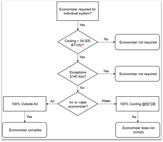
Figure 4-27: Single-Fan Dual-Duct Systems

Example 4-36
Question
If the design conditions are 94 degrees F db/82 degrees F wb can the design cooling loads to size a water-side economizer?
Answer
No. The design coo4-36ing load calculations must be rerun with the outdoor air temperature set to 50 degrees F db/45 degrees F wb. The specified tower, as well as cooling coils and other devices, must be checked to determine if it has adequate capacity at this lower load and wet-bulb condition.
Example 4-37
Question
Will a strainer cycle water-side economizer meet the prescriptive economizer requirements? (Refer to Figure 4-36)
Answer
No. It cannot be integrated to cool simultaneously with the chillers.
Example 4-38
Question
Does a 12 ton packaged AC unit in climate zone 10 need an economizer?
Answer
Yes. In addition, the economizer must be equipped with a fault detection and diagnostic system. However, the requirement for an economizer can be waived if the AC unit’s efficiency is greater than or equal to an EER of 14.3. Refer to Table 4-20.
4.5.2.3 Variable Air Volume (VAV) Supply Fan Controls
Both single and multiple zone systems are required to have VAV supply based on the system type as described in Table 4-21. The VAV requirements for supply fans are as follows:
1. Single zone systems (where the fans are controlled directly by the space thermostat) shall have a minimum of two stages of fan speed with no more than 66 percent speed when operating on stage one while drawing no more than 40 percent full fan power when running at 66 percent speed.
2. All systems with air-side economizers to satisfy Section 4.5.2.2 are required to have a minimum of 2 speeds of fan control during economizer operation.
3. Multiple zone systems shall limit the fan motor demand to no more than 30 percent of design wattage at 50 percent design air volume.
Variable speed drives can be used to meet any of these three requirements.
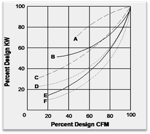
Actual fan part-load performance, available from the fan manufacturer, should be used to test for compliance with item 3 above. Figure 4-28 shows typical performance curves for different types of fans. Both air foil fans and backward inclined fans using either discharge dampers or inlet vanes consume more than 30 percent power at 50 percent flow (when certified manufacturer’s test data shows static pressure set point is one-third of total design static pressure). These fans will not normally comply with these requirements unless a variable speed drive is used.
VAV fan systems that do not have DDC to the zone level are required to have the static pressure sensor located in a position such that the control set point is less than or equal to 1/3 of the design static pressure of the fan. For systems without static pressure reset, the further the sensor is from the fan the more energy will be saved. For systems with multiple duct branches in the distribution separate sensors in each branch must be provided to control the fan and to satisfy the sensor with the greatest demand. When locating sensors, care should be taken to have at least one sensor between the fan and all operable dampers (e.g. at the bottom of a supply shaft riser before the floor fire/smoke damper) to prevent loss of fan static pressure control.
For systems with DDC to the zone level the sensor(s) may be anywhere in the distribution system and the duct static pressure set point must be reset by the zone demand. Typically, this is done by one of the following methods:
1. Controlling so that the most open VAV box dampers are 95 percent open.
2. A trim and respond algorithm to continually reduce the pressure until one or more zones indicate that they are unable to maintain airflow rate set points.
3. Other methods that dynamically reduce duct static pressure setpoint as low as possible while maintaining adequate pressure at the VAV box zone(s) of greatest demand.
Reset of supply pressure by demand not only saves energy but it also protects fans from operation in surge at low loads. Chapter 13, Acceptance Requirements, describes mandated acceptance test requirements for VAV system fan control.
Figure 4-28: VAV Fan Performance Curve
|
|
A. Air foil or backward inclined centrifugal fan
with discharge dampers B. Air foil centrifugal fan with inlet
vanes C. Forward curved centrifugal fan with discharge
dampers or riding curve D. Forward curved centrifugal fan with inlet
vanes E. Vane-axial fan with variable pitch
blades F. Any fan with variable speed drive (mechanical drives will be slightly less efficient) |
|
Cooling System Type |
Fan Motor Size |
Cooling Capacity |
|
DX Cooling |
any |
≥ 65,000 Btu/hr |
|
Chilled Water and Evaporative |
≥ 1/4 HP |
any |
Source: California Energy Commission, Building Energy Efficiency Standards, Table 140.4-D
4.5.2.4 Supply-Air Temperature Reset Control
Mechanical space-conditioning systems supplying heated or cooled air to multiple zones must include controls that automatically reset the supply-air temperature in response to representative building loads or to outdoor air temperature. The controls must be capable of resetting the supply-air temperature by at least 25 percent of the difference between the design supply-air temperature and the design room air temperature.
For example, if the design supply temperature is 55 degrees F and the design room temperature is 75 degrees F, then the difference is 20 degrees F, of which 25 percent is 5 degrees F. Therefore, the controls must be capable of resetting the supply temperature from 55 degrees F to 60 degrees F.
Air distribution zones that are likely to have constant loads, such as interior zones, shall have airflow rates designed to meet the load at the fully reset temperature. Otherwise, these zones may prevent the controls from fully resetting the temperature, or will unnecessarily limit the hours when the reset can be used.
Supply air reset is required for VAV reheat systems even if they have variable-speed drive (VSD) fan controls. The recommended control sequence is to lead with supply temperature set point reset in cool weather where reheat might dominate the equation and to keep the chillers off as long as possible. Thereafter the system can return to a fixed low set point in warmer weather when the chillers are likely to be on. During reset a demand-based control is employed that uses the warmest supply air temperature to satisfy all of the zones in cooling.
This sequence is described as
follows: during occupied mode the set point is reset from
T-min (53 degrees
F) (when the outdoor air temperature is 70 degrees F and above) proportionally
up to T-max (when the outdoor air temperature is 65 degrees F and below). T-max
shall range from 55 degrees F to 65 degrees F and shall be the output of a slow
reverse-acting proportional-integral loop that maintains the cooling loop of the
zone served by the system with the highest cooling loop at a set point of 90
percent (See Figure 4-29)
Supply temperature reset is also required for constant volume systems with reheat justified on the basis of special zone pressurization relationships or cross-contamination control needs.
Supply-air temperature reset is not required when:
1. The zone(s) must have specific humidity levels required to meet exempt process needs. Computer rooms cannot use this exception.
2. Where it can be demonstrated (to the satisfaction of the enforcement agency) that supply air reset would increase overall building energy use.
3. The space-conditioning zone has controls that prevent reheating and recooling and simultaneously provide heating and cooling to the same zone.
4. Systems serving healthcare facilities.
Figure 4-29: Energy Efficient Supply Air Temperature Reset Control for VAV Systems
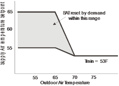
Recommended Supply Air Temperature Reset Method
4.5.2.5 Heat Rejection Fan Control
When the fans on cooling towers, closed-circuit fluid coolers, air-cooled condensers and evaporative condensers are powered by a fan motor of 7.5 hp or larger, the system must be capable of operating at two-thirds speed, or less. In addition, the system must have controls that automatically change the fan speed to control the leaving fluid temperature or condensing temperature or pressure of the heat rejection device. Fan speed controls are exempt when:
1. Fans are powered by motors smaller than 7.5 hp.
2. Heat rejection devices are included as an integral part of the equipment listed in Table 4-1 through Table 4-11 .
3. Condenser fans serving multiple refrigerant circuits or flooded condensers.
4. Up to one third of the fans on a condenser or tower with multiple fans have lead fans that comply with the speed control requirement.
Example 4-39
Question
A chilled water plant has a three-cell tower with 10 hp motors on each cell. Are speed controls required?
Answer
Yes. At minimum the designer must provide 2-speed motors, pony motors or variable speed drives on two
of the three fans for this tower.
4.5.2.6 Hydronic System Measures
A. Hydronic Variable Flow Systems
Hot water and chilled-water systems are required to be designed for variable flow. Variable flow is provided by using 2-way control valves. The Energy Standards only require that flow is reduced to whichever value is greater: 50 percent or less of design flow or the minimum flow required by the equipment manufacturer for operation of the central plant equipment.
There are two exceptions for this requirement:
1. Systems that include no more than three control valves.
2. Systems having a total pump system power less than or equal to 1.5 hp.
It is not necessary for each individual pump to meet the variable flow requirement. These requirements can be met by varying the total flow for the entire pumping system in the plant. Strategies that can be used to meet these requirements include but are not limited to variable frequency drives on pumps and staging of the pumps.
The primary loop on a primary/secondary or primary/secondary/tertiary system could be designed for constant flow even if the secondary or tertiary loop serves more than three control valves. This is allowed because the primary loop does not directly serve any coil control valves. However, the secondary and tertiary loops of these systems must be designed for variable flow if they have four or more control valves.
The flow limitations are provided for primary-only variable flow chilled-water systems where a minimum flow is typically required to keep a chiller on-line. In these systems minimum flow can be provided with either a bypass with a control valve or some three-way valves to ensure minimum flow at all times. The system with a bypass valve is more efficient as it only provides bypass when absolutely required to keep the plant on line.
For hot water systems, application of slant-tube or bent tube boilers will provide the greatest flow turndown. Typically, copper fin tube boilers require a higher minimum flow.
Example 4-40
Question
A plant is trying to meet the variable flow requirements of Section 4.5.2.6. Must each individual pump meet these requirements for the plant to comply with the Energy Standards?
Answer
No. Individual pumps do not need to meet the variable flow requirements of this section. As long as the entire plant meets the variable flow requirements, the plant is in compliance. For example, the larger pumps may be equipped with variable frequency drives or the pumps can be staged in a way that can meet these requirements.
B. Isolation for Chillers and Boilers
§140.4(k)2 and 3
Plants with multiple chillers or boilers are required to provide either isolation valves or dedicated pumps. In addition, they must check valves to ensure that flow will only go through the chillers or boilers that are staged on. Chillers that are piped-in series for the purpose of increased temperature differential shall be considered as one chiller.
C. Chilled and Hot Water Reset
Similar to the requirements for supply air temperature reset, chilled and hot water systems that have a design capacity greater than 500,000 Btu/h are required to provide controls to reset the hot or cold water temperature set points as a function of building loads or the outdoor air temperature. This reset can be achieved either using a direct indication of demand (usually cooling or heating valve position) or an indirect indication of demand (typically outdoor air temperature). On systems with DDC controls reset using valve position is recommended.
Exceptions for this requirement:
1. Hydronic systems that are designed for variable flow complying with §140.4(k)1
2. Systems serving healthcare facilities
D. Isolation Valves for Water-Loop Heat Pump Systems
Water-circulation systems serving water-cooled air conditioner and hydronic heat pump systems with a design circulation pump brake horsepower greater than five bhp are required to be provided with 2-way isolation valves that close whenever the compressor is off. These systems are also required to be provided with the variable speed drives and pressure controls described in the following section.
Although not required on central tenant condenser water systems (for water-cooled AC units and HPs) it is beneficial to provide the 2-way isolation valves on these systems as well. In addition to providing pump energy savings, these 2-way valves can double as head-pressure control valves allowing aggressive condenser water reset for energy savings in chilled water plants that are also cooled by the towers.
E. Variable-speed drive for Pumps Serving Variable Flow Systems
Pumps on variable flow systems that have a design circulation pump brake horsepower greater than 5 bhp are required to have variable-speed drives. Alternatively, they may have a different control that will result in pump motor demand of no more than 30 percent of design wattage, at 50 percent of design water flow.
Pressure Sensor Location and Set point
1. For systems without direct-digital control of individual coils reporting to the central control panel, differential pressure must be measured at the most remote heat exchanger or the heat exchanger requiring the most pressure. This includes chilled-water systems, condenser water systems serving water-cooled air conditioning loads and water-loop heat pump systems.
2. For systems with direct digital control of individual coils with a central control panel, the static pressure set point must be reset based on the valve requiring the most pressure and the set point shall be no less than 80 percent open. The pressure sensor(s) may be mounted anywhere.
Exceptions are provided for hot-water systems and condenser water systems that only serve water-cooled chillers. The hot water systems are exempted because the heat from the added energy of the pump riding the curve provides a beneficial heat that reduces the boiler use. This diminishes the benefit from the reduced pumping energy.
F. Hydronic Heat Pump (WLHP) Controls
Hydronic heat pumps connected to a common heat pump water loop with central devices for heat rejection and heat addition must have controls that are capable of providing a heat pump water supply temperature dead band of at least 20 degrees F between initiation of heat rejection and heat addition by the central devices. Exceptions are provided where a system loop temperature optimization controller is used to determine the most efficient operating temperature based on real-time conditions of demand and capacity, dead bands of less than 20 degrees F shall be allowed.
4.5.2.7 Window/Door Switches for Mechanical System Shut Off
If a directly conditioned zone has a thermostat and one or more manually operable wall or roof openings to the outdoors, then the openings must all have sensors that communicate to the HVAC system. The HVAC controller must be capable of shutting off the heating or cooling to that zone if the sensor detects that the opening has remained open for more than five minutes. This can be accomplished by resetting the heating set point to 55 degrees F or the heating can be disabled altogether. If the HVAC system is in cooling mode, then similarly this requirement can be satisfied by resetting the cooling set point to 90 degrees F -unless the outside air temperature is less than the space temperature, in which case the cooling set point can be reset, or not. If the zone is in cooling and the outside air temperature is less than the space temperature, then additional infiltration from the opening provides economizer-free cooling and is not an additional cooling load on the mechanical system.
This requirement does not require any openings to the outdoors to.be operable. However, if operable openings are present, then they must comply with this requirement.
Mechanical ventilation as required by Section 4.3.2 must still be provided. The mechanical system shut off pertains to the space conditioning equipment only. Mechanical ventilation must still be provided if the space does not fall under the natural ventilation criteria. Systems that meet the ventilation requirements with natural ventilation, rather than mechanical ventilation, are not exempt from the window/door switch requirement. Thus, in the same way that most homeowners typically choose between opening the windows and running the heating/cooling, window/door switches will now cause occupants to choose between opening windows/doors and allowing full heating/cooling.
Manually operable openings to the outdoors include manually operable windows, skylights, and doors that do not have automatic closing devices (e.g. sliding balcony doors). Motorized openings (e.g., motorized skylights) are still considered manually operable if occupants can move the openings as desired and they will stay open until manually closed.
If a zone serves more than one room, then only the openings in the room with the thermostat are required to be interlocked. For example, if three perimeter private offices are served by a single VAV box then only the operable openings in the office with the thermostat need to be interlocked. The windows in the offices that do not have a thermostat do not need to be interlocked.
If there is a large room with more than one zone, then only the zones with operable windows in them need to be interlocked. For example, if a large open office has a perimeter zone and an interior zone in the same room and there are operable windows in the perimeter zone but not the interior zone then only the perimeter zone thermostat needs to be interlocked to the windows.
Exceptions to this requirement:
1. Interlocks are not required on doors with automatic closing devices
2. ![]()
![]() Any space without a
thermostatic control
Any space without a
thermostatic control
4. High-rise residential dwelling units
Alterations to existing buildings are exempt from this requirement. Additions to existing buildings only have to comply if the operable opening(s) and associated zone are new.
There are a number of acceptance requirements related to control systems. These include:
1. Automatic time switch control devices
2. Constant volume package unit
3. Air-side economizers
4. VAV supply fan controls
5. Hydronic-system controls
These tests are described in Chapter 13 as well as the Reference Nonresidential Appendix NA7.