
This chapter details the eligibility requirements for candidate simulation program for use as compliance software. A series of quantitative tests called software sensitivity tests shall be performed to measure the change in energy consumption when changing specified input parameters. Candidate software results will be compared against predetermined reference results to demonstrate that the candidate software is acceptable for use in code compliance. All the test cases described in Appendix 3A shall be performed and results summarized in the forms contained in Appendix 3B.
The candidate software shall perform a suite of software sensitivity tests to demonstrate that the performance is acceptable for code compliance. The candidate software test results shall be compared against a base case called the reference test case. The reference test case is the corresponding match of a particular test case simulated already on EnergyPlus engine. The reference test case results, as determined by the CEC, are tabulated in Appendix 3B.
Test cases specific for simplified geometry are only for software with 2D inputs for building geometry. Software with a 2D geometry approach shall seek certification by submitting the simplified geometry test cases. In addition, they are also required to produce results for HVAC tests that will be compared against the HVAC reference test results that are common for both simplified and detailed geometry.
The test cases will assess the sensitivity of the candidate software to various inputs ranging from envelope thermal conductance to HVAC system performance. Each case tests the effect of the input component on building end-use energy and annual TDV. The following six building components will be tested through a series of tests:
- Opaque envelope
- Glazing
- Lighting
- Daylighting
- Receptacle loads
- HVAC system parameters
The software sensitivity tests are performed on four nonresidential and two multifamily prototypes. The nonresidential prototype models are a subset of the U.S. Department of Energy (DOE) prototype building models developed by PNNL for analysis of ASHRAE Standard 90.1. Furthermore, the nonresidential prototype models are EnergyPlus model input files of the DOE prototype building models, modified to comply with the requirements of Title 24. The prototype models will be the reference baseline runs for the test cases. The candidate software shall replicate the building models below using the same inputs as the prototype models. The models so replicated will be the candidate baseline models for the test cases.
A summary of the prototype models is provided in Appendix 3A. Detailed input files of the reference baseline models are available from the CEC’s Building Energy Efficiency Software Consortium web page at http://bees.archenergy.com/.
Prototype models used for software sensitivity test cases are:
Small Office (02000CZ-OffSml):

Source: California Energy Commission
The small office building model is a single-story rectangular building of 5,500 square feet. It has punched windows and a hipped roof with an attic. There are five zones, each served by packaged single-zone air conditioner units. For more details refer Appendix 3A. This prototype is used for simple geometry test cases only.
Medium Office Building (0300CZ-OffMed):

Source: California Energy Commission
The medium office building model is a three-story rectangular building with an overall area of 53,600 square feet. It has a window-to-wall ratio of 33 percent with fenestration distributed evenly across all four façades. The zones are served by DX cooling and gas furnace heating with hot water reheat. For more details refer Appendix 3A. This prototype is used for both detailed geometry and simple geometry test cases.
Large Office Building (0400CZ-OffLrg):

Source: California Energy Commission
The large office building has 12 floors and a basement floor with glass windows with a window-to-wall ratio of 40 percent on the above-grade walls. The total area of the building is 498,600 square feet. The HVAC system type used is a variable air volume (VAV) system. For more details refer Appendix 3A.
Stand-Alone Retail (0500CZ-RetlMed):

Source: California Energy Commission
The stand-alone retail building is a single-story rectangular building measuring 178 feet by 139 feet. The total area is 24,695 square feet. Windows are located only on the street-facing façade and occupy 25.4 percent of that façade. The building is divided into five thermal zones that are served by packaged single-zone systems as described in Appendix 3A. This prototype is used for both detailed geometry and simple geometry test cases.
Strip Mall Building Strip Mall-PSZ System (1000CZ-RetlStrp):

Source: California Energy Commission
The strip mall building area is 22,500 square feet. It has 10 zones each with rooftop units. The building has windows in the street-facing façade and has an overall window-to-wall ratio of 10.5 percent. For more details refer to Appendix 3A.
Loaded Corridor Multifamily Building (MF36nit_Story):
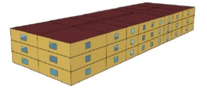
The loaded corridor multifamily building is a three-story residential building with 39,372 square feet of building area, 36 residential units, flat roof, slab on-grade foundation and wood framed wall construction, and a window to wall ratio of 0.25. For more details refer to Appendix 3A.
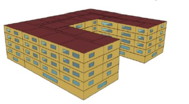
Mid-Rise Mixed-Use Building (MF88Unit_5Story):
Source: California Energy Commission
The mid-rise mixed-use building is a five story 113,100 square feet mixed use building. The building has one ground floor of nonresidential space and four additional stories of residential space, 88 residential units, flat roof, underground parking garage, concrete podium construction, wood-framed wall construction, and a window-to-wall ratio of 0.10 (ground floor) and 0.25 (residential floors). For more details, refer to Appendix 3A.
The software sensitivity test cases use building models for 5 of the 16 California climate zones. Most tests are performed with two or three climate zones to capture the sensitivity of the input characteristics to extremes in weather conditions. The test cases are performed in climate zones that represent mild, hot, and cold climates respectively.
Climate Zone | Example City/Weather File |
1 | Arcata/ARCATA_725945 |
6 | Torrance/TORRANCE_722955 |
7 | San Diego Lindbergh/ SAN-DIEGO-LINDBERGH_722900 |
15 | Palm Springs/PALM-SPRINGS-INTL_722868 |
16 | Blue Canyon/BLUE-CANYON_725845 |
Each test case in the software sensitivity test is labeled uniquely to make it easier to keep track of the runs and facilitate analysis. The following scheme is used:
XXYYYZZ-Prototype-RunDescription
Where:
- XX denotes the Prototype Number
- YY denotes Test Run Number
- ZZ denote Climate zone
Detailed Geometry Example:

Simplified Geometry Example:

Candidate software vendors shall perform a series of computer runs. Each of these runs shall be a systematic variation of the candidate base case model as described in Chapter 3.5.1.7: Software Sensitivity Test Cases. The applicant test case results will be compared to the reference results to verify that candidate software meets the requirements of the Nonresidential and Multifamily ACM Reference Manual. Simulation results for each test case will be compiled in forms provided in Appendix 3B. Compiled results will include annual site energy consumption for each end use, overall site energy consumption, total unmet load hours, annual TDV and percentage variation of annual TDV, annual Source Energy and percent variation of annual Source Energy, and total end use site energy.
The annual TDV percentage variation shall be calculated using the formula:
TDV%= (TDVb – TDVn)/TDVb
Where, TDV% is the TDV percentage variation,
- TDVn is the annual TDV for test case number n and
- TDVb is the annual TDV for the base case run.
- The annual Source Energy percentage variation shall be calculated using the formula:
- Source Energy% = (Source Energyb – Source Energyn)/Source Energyb
- Source Energy% is the Source Energy percentage variation,
- Source Energyn is the Source Energy for test case number n and
- Source Energyb is the Source Energy for the base case run.
To be accepted, the candidate software should fulfill the passing criteria as determined by the CEC:
For each test case the change in energy for the test case must be in the same direction as the Reference Method test case result and must be equal to the Reference Method test case percentage change in TDV energy, plus or minus 0.5 percent of baseline TDV energy.
If any of the tests required for the Title 24 compliance feature set fails to meet these criteria, the candidate software will not be accepted for compliance use.
For each test case, the TDV energy use of the modeled building is reported (kBtu/ft2), along with the TDV energy use attributed to the major fuel types (electricity, gas), site energy use, and energy end-use intensity for the regulated end uses (cooling, heating, lighting, and so forth). The following energy totals are reported:
- Annual TDV EUI (kBtu/ft2)
- Annual Source Energy EUI (kBtu/ft2)
- Annual SiteEUI – Electricity (kWh/ft2)
- Annual SiteEUI – Natural Gas (therm/ft2)
- Annual Total End Use Site Energy EUI – kBtu/ft2
Site Energy End Uses
- Site Energy: Heating (kBtu/ft2)
- Site Energy: Cooling (kBtu/ft2)
- Site Energy: Interior Lighting (kBtu/ft2)
- Site Energy: Interior Equipment (kBtu/ft2)
- Site Energy: Fans (kBtu/ft2) (Airside Fans, does not include tower fans)
- Site Energy: Pumps (kBtu/ft2)
- Site Energy: Towers (kBtu/ft2)Water heating (kBtu/ft2)
- TDV Percentage Variation – this field is used for the compliance test
- Total End Use Site Energy percent - percentage change in site energy use
- Pass/Fail – test fails if it does not meet passing criteria
- Unmet load hours (UMLH) – defined as the zone with the most UMLH
- Reference Model Occupied UMLH
- Candidate Model Occupied UMLH
- Reference Model Number of Zones with excess UMLH (>150)
- Candidate Model Number of Zones with excess UMLH (>150)
Figure 3: Results Spreadsheet Excerpt From Appendix 3B

Source: California Energy Commission
The results spreadsheet provides the results of the reference method for each test and provides a column for the vendor to report the results from the candidate software.
The variation from baseline section of the spreadsheet shows the percentage change in TDV energy use (kBtu/ft2) and source energy from the base case for testing. The percentage must be within the passing criteria for the candidate software to pass this test.
Also reported is the number of UMLH during occupied hours for the building. An UMLH for a specific zone in Title 24 compliance is defined as any hour when the zone has an unmet cooling or heating load. This is typically reported by the candidate software for each zone in the building. For the test case results, two unmet load hour metrics must be reported: the number of UMLH for the zone with the greatest number of UMLH, and the number of zones that fail the Nonresidential and Multifamily ACM Reference Manual criteria for acceptable UMLH. (Any zones with greater than 150 hours fail the criteria.)
The spreadsheet where the results are documented indicates whether the candidate software passes or fails a test. The result in column AL of the spreadsheet indicates whether the candidate software passes the test.
Test cases assess the energy impact of one or more of the building or system input characteristics on the baseline model. Each test suite consists of a series of unique test cases aimed to test the effect of a specific characteristic on building energy performance. Simulations are grouped according to test criteria and subgrouped based on the reference model type to allow for direct comparison of results. For each test case, the candidate software will modify the candidate baseline model with specific inputs as described in the test case description chapter.
The test cases are simulated on multiple California weather files to evaluate the sensitivity of the building or system input to extremes in climate. Results of the test case runs and the TDV percentage variation over the baseline run shall be compiled and compared against the reference results.
Detailed descriptions of the standard design models are provided in Appendix 3A. CBECC input files for all baseline and test case models are available from the CEC’s, Building Energy Efficiency Software Consortium web page http://bees.archenergy.com. Details on each test description can be found in Appendix 3A under the test criteria tab.
The applicant shall perform simulations for all tests specified above. A detailed description of each test case is provided in Appendix 3A, and report results in the forms are provided in Appendix 3B. Some of the prototype models have variants of the baseline model. These include 1) stand-alone duct loss baseline, a variant of the stand-alone retail model; 2) StripMall-PTAC model, a variant of StripMall-PSZ model; and 3) StripMall-Fan Coil model, a variant of StripMall- PSZ model. For details refer to Appendix 3A.
Three test cases are presented here as an example: one for building envelope, one for lighting and daylighting, and one for HVAC. The development of the other required test cases follows the same process.
Example Test Case: 0301315-OffMed-GlazingWindowSHGC
For this test case, the U-factor and solar heat gain coefficient (SHGC) of all vertical fenestration is decreased by 20 percent. The prototype used for this test case is a medium office building.
Before the test cases are run, the first step is to generate the prototype models for the four reference buildings, which are required for all of the tests. The four prototype models are defined in the prototype model spreadsheet of Appendix 3A. (Note: While many of the prototype model inputs are based on Title 24 prescriptive requirements, the prototype models do not exactly conform to minimum Title 24 requirements but are intended to test the sensitivity of the candidate software simulation results to common variations in building inputs.)
STEP 1: GENERATE PROTOTYPE MODELS.
The first step is to generate the prototype building for the medium office building. The detailed specification of the medium office building is listed in Appendix 3A. A portion of the inputs are shown in Figure 4: Prototype Model Definition from Appendix 3A. The prototypes are defined for the reference models on the prototype model tab of Appendix 3A.
Figure 4: Prototype Model Definition From Appendix 3A

Source: California Energy Commission
The prototype model definition in the spreadsheet contains links to other input definitions:
Rows 19, 26, 45: Links to layer-by-layer exterior construction assembly definitions in the Construction Assembly tab
Row 52: Links to layer-by-layer interior construction assembly definitions in the Construction Assembly tab
STEP 2: DEFINE BASE CASE AND VARIATION FOR TEST RUN.
The base case is defined as the starting point for each test. In many tests, the base case will be one of the prototype models. However, in some cases a variation of the prototype may serve as the base case for the test.
For this test, the base case is found by looking at the test criteria tab of Appendix 3A.
Figure 5: Base Case Definition From Appendix 3A

Source: California Energy Commission
For this test, the baseline field in row 3 of the Test Criteria tab shows that the baseline is CZ06MediumOffice, the medium office prototype in Climate Zone 6.
This same Test Criteria tab shows the input(s) to be verified, which are highlighted in purple. For this test, the SHGC of all vertical fenestration is reduced by 20 percent, from 0.25 to 0.20.
Figure 6: Input Parameter Variation for Medium Office From Appendix 3A

Source: California Energy Commission
STEP 3: RUN THE BASE CASE MODEL AND GENERATE TEST RESULTS.
Once the base case model is developed, the simulation is run, and the results are recorded onto the spreadsheet of test cases. See Appendix 3B.
The candidate software shall report electricity use by end use, gas use by end use, TDV energy, and UMLH. For compliance, UMLH are defined at the zone level, and the zone with the greatest number of UMLH must pass the criteria specified in the sizing procedure.
For the reference tests, the capacities and flow rates of the HVAC system can be found in Appendix 3A under the Sizing Values tab.
STEP 4: RUN THE TEST CASE MODELL (WITH THE REDUCED SHGC) AND REPORT THE RESULTS.
The model is rerun, and the energy results and outputs are reported. The percentage change in energy use is reported.
STEP 5: REPORT THE CHANGE IN REGULATED TDV ENERGY USE AND SOURCE ENERGY USE FROM THE BASE CASE AS A PERCENTAGE CHANGE.
The reported percentage change in energy use from the candidate software must fall within the passing criteria for the reference method.