
Nonresidential and hotel/motel buildings shall comply with the applicable requirements of Sections 120.3(a) through 120.3(c).
4. Process heating system piping. All refrigerant, steam, steam condensate and hot water fluid distribution systems for heating a process unrelated to space conditioning or service water-heating.
5. Process cooling system piping. All refrigerant suction, chilled water, and brine fluid distribution systems for cooling a proves unrelated to space conditioning.
Insulation conductivity shall be determined in accordance with ASTM C335 at the mean temperature listed in Table 120.3-A1 or Table 120.3-A-2, and shall be rounded to the nearest 1/100 Btu-inch per hour per square foot per °F. Fluid distribution systems include all elements that are in series with the fluid flow, such as pipes, fittings, pumps, valves, strainers, coil u-bends, and air separators, but not including elements that are not in series with the fluid flow, such as expansion tanks, fill lines, chemical feeders, and drains.
Exception to Section 120.3(a)2: Heat pump refrigerant vapor line shall be installed with a minimum of 0.5 inch thick or R‐3.0 insulation for nonresidential buildings and 0.75 inch thick or R‐6.0 insulation for residential buildings. No insulation is required on the refrigerant liquid line.
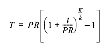
WHERE:
T = insulation thickness for material with conductivity K, inches.
PR = actual outside radius, inches.
t = Insulation thickness from Table 120.3-A-1 or Table 120.3-A-2, inches.
K = Conductivity of alternate material at the mean rating temperature indicated in Table 120.3-A for the applicable fluid temperature range, in Btu-inch per hour per square foot per °F.
k = The lower value of the conductivity range listed in Table 120.3-A for the applicable fluid temperature range, Btu-inch per hour per square foot per °F.
| Fluid Operating Temperature Range (°F) | Insulation Conductivity (in Btu·in./ft²·h·°F) | Insulation Mean Rating Temperature (°F) | Nominal Pipe Diameter < 1 inch | Nominal Pipe Diameter 1 to < 1.5 inches | Nominal Pipe Diameter 1.5 to < 4 inches | Nominal Pipe Diameter 4 to < 8 inches | Nominal Pipe Diameter 8 inches and larger |
| Above 350 | 0.32-0.34 | 250 | 4.5 inches | 5.0 inches | 5.0 inches | 5.0 inches | 5.0 inches |
| Above 350 | 0.32-0.34 | 250 | R 37 | R 41 | R 37 | R 27 | R 23 |
| 251-350 | 0.29-0.32 | 200 | 3.0 inches | 4.0 inches | 4.5 inches | 4.5 inches | 4.5 inches |
| 251-350 | 0.29-0.32 | 200 | R 24 | R 34 | R 35 | R 26 | R 22 |
| 201-250 | 0.27-0.30 | 150 | 2.5 inches | 2.5 inches | 2.5 inches | 3.0 inches | 3.0 inches |
| 201-250 | 0.27-0.30 | 150 | R 21 | R 20 | R 17.5 | R 17 | R 14.5 |
| 141-200 | 0.25-0.29 | 125 | 1.5 inches | 1.5 inches | 2.0 inches | 2.0 inches | 2.0 inches |
| 141-200 | 0.25-0.29 | 125 | R 11.5 | R 11 | R 14 | R 11 | R 10 |
| 105-140 | 0.22-0.28 | 100 | 1.0 inch | 1.5 inches | 1.5 inches | 1.5 inches | 1.5 inches |
| 105-140 | 0.22-0.28 | 100 | R 7.7 | R 12.5 | R 11 | R 9 | R 8 |
Fluid Operating Temperature Range (°F) | Insulation Conductivity | Insulation Mean Rating Temperature (°F) | Nominal Pipe Diameter < 1 inch | Nominal Pipe Diameter 1 to < 1.5 inches | Nominal Pipe Diameter 1.5 to < 4 inches | Nominal Pipe Diameter 4 to < 8 inches | Nominal Pipe Diameter 8 inches and larger |
Residential 40-60 | 0.21-0.27 | 75 | 0.75 inch | 0.75 inch | 1.0 inch | 1.0 inch | 1.0 inch |
Residential 40-60 | 0.21-0.27 | 75 | R-6 | R-5 | R-7 | R-6 | R-5 |
Nonresidential 40-60 | 0.21-0.27 | 75 | 0.5 inch | 0.5 inch | 1.0 inch | 1.0 inch | 1.0 inch |
Nonresidential 40-60 | 0.21-0.27 | 75 | R-3 | R-3 | R-7 | R-6 | R-5 |
Below 40 | 0.20-0.26 | 50 | 1.0 inch | 1.5 inches | 1.5 inches | 1.5 inches | 1.5 inches |
Below 40 | 0.20-0.26 | 50 | R-8.5 | R-14 | R-12 | R-10 | R-9 |
Footnote to Table 120.3-A-1 and Table 120.3-A-2:
These thicknesses are based on energy efficiency considerations only. Issues such as water vapor permeability or surface condensation sometimes require vapor retarders or additional insulation.
Exception 1 to Section 120.3: Factory-installed piping within space-conditioning equipment certified under Section 110.1 or 110.2.
Exception 2 to Section 120.3: Piping that conveys fluids with a design operating temperature range between 60°F and 105°F.
Exception 3 to Section 120.3: Where the heat gain or heat loss to or from piping without insulation will not increase building source energy use.
Exception 4 to Section 120.3: Piping that penetrates framing members shall not be required to have pipe insulation for the distance of the framing penetration. Metal piping that penetrates metal framing shall use grommets, plugs, wrapping or other insulating material to assure that no contact is made with the metal framing.
Exception 5 to Section 120.3: Fluid pumps, steam traps, blow-off valves, and piping within process equipment.
Exception 6 to Section 120.3: Valves, strainers, coil u-bends, air separators with at least 0.5 inches of insulation, and piping within process equipment.
Note: Authority: Sections 25213, 25218, 25218.5, 25402 and 25402.1, Public Resources Code. Reference: Sections 25007, 25008, 25218.5, 25310, 25402, 25402.1, 25402.4, 25402.5, 25402.8, and 25943, Public Resources Code.