
3. Multi-zone space-conditioning system types. Space-conditioning systems in office buildings and school buildings not covered by Section 140.4(a)2 shall meet the following requirements:
Exception 1 to Section 140.4(a)3: Buildings greater than 150,000 square feet or greater than five (5) habitable stories.
Exception 2 to Section 140.4(a)3: School buildings in Climate Zones 6 and 7.
- For Office buildings: The portion of perimeter zone terminal unit heating capacity utilizing parallel fan-powered boxes complying with Section 140.4(a)3E shall be:
1. 100 percent in climate zones 1 through 6, and 16.
2. 25 percent in climate zones 7 through 15.
Ventilation systems in Climate Zones 1, 3, and 5 shall be equipped with a heat recovery system in compliance with Section 140.4(q). The maximum allowed fan power in Climate Zones 3 and 5 shall be 15 percent lower than specified by Section 140.4(c)1.
b. For school buildings:
All perimeter zone terminal units shall be parallel fan powered boxes complying with Section 140.4(a)3E.
Ventilation systems in climate zones 2, 4, and 11 through 16 shall be equipped with a heat recovery system in compliance with Section 140.4(q).
The maximum allowed fan power in climate zone 2 shall be 15 percent lower than specified by Section 140.4(c)1.
The design leaving water temperature of the heating loop shall be no greater than 120°F in climate zone 2.
a. When required by Section 140.4(e), economizers shall be located on the cold deck,
b. The hot deck shall supply 100% return air, except outdoor air may be supplied as required to supplement the cold deck to maintain the design minimum outdoor air rate,
c. The hot deck heating source shall be a heat pump, and
d. The DFDD and DFDD terminal unit control sequence shall comply with ASHRAE Guideline 36.
- The minimum efficiency requirements specified in Table 110.2-J,
- If chilled water produced by an AWHP is used for space-cooling then the heat recovery system shall comply with Section 140.4(s),
- Supplemental heating shall be provided by an electric resistance boiler with a capacity of not greater than 50 percent of the design space-heating hot water loop heating capacity.
i. For hydronic heating or cooling:
a. DOAS heating coils shall be hydronic heating coils utilizing the AWHP space-heating hot water loop.
b. DOAS cooling coils shall be hydronic cooling coils utilizing space-cooling chilled water loop.
ii. Other heating or cooling shall be provided by a heat pump. Electric resistance heating shall not be used.
i. Outdoor design conditions shall be selected from Reference Joint Appendix JA2 shall be used, which is based on data from the ASHRAE Climatic Data for Region X or the ASHRAE Handbook, Fundamentals Volume.
ii. Heating design temperatures shall be no lower than the 99.0 percent Heating Dry Bulb or the Heating Winter Median of Extremes values.
iii. Cooling design temperatures shall be no greater than the 0.5 percent Cooling Dry Bulb and Mean Coincident Wet Bulb values.
Exception to Section 140.4(b)3: Cooling design temperatures for cooling towers shall be no greater than the 0.5 percent cooling design wet bulb values.
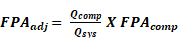
Where
FPAadj = The corrected fan power allowance for the component in w/cfm
Qcomp = The airflow through component in cfm
Qsys = The fan system airflow in cfm
FPAcomp = The fan power allowance of the component from Table 140.4A or Table 140.4B
Exception to Section 140.4(c)1: Systems whose fan power is specified in Section 140.4(a)3
Standard 210-2016, AHRI Standard 430-2020, AHRI Standard 440-2019, or ISO 5801-2017.
Airflow | Multi-Zone VAV Systems | Multi-Zone VAV Systems > 5,000 and ≤ 10,000 cfm1 | Multi-Zone VAV Systems > 10,000 cfm1 | All Other Fan Systems ≤ 5,000 cfm | All Other Fan Systems > 5,000 and ≤ 10,000 cfm | All Other Fan Systems |
Supply System Base Allowance for AHU serving spaces ≤ 6 floors away. | 0.395 | 0.453 | 0.413 | 0.232 | 0.256 | 0.236 |
Supply system base allowance for AHU serving spaces > 6 floors away | 0.508 | 0.548 | 0.501 | 0.349 | 0.356 | 0.325 |
MERV 13 to MERV 16 Filter upstream of thermal conditioning equipment (two times the clean filter pressure drop)2 | 0.136 | 0.114 | 0.105 | 0.139 | 0.120 | 0.107 |
MERV 13 to MERV 16 Final filter downstream of thermal conditioning equipment. (two times the clean filter pressure drop)2 | 0.225 | 0.188 | 0.176 | 0.231 | 0.197 | 0.177 |
Filtration allowance for > MERV 16 or HEPA Filter (two times the clean filter pressure drop) 2 | 0.335 | 0.280 | 0.265 | 0.342 | 0.292 | 0.264 |
Central Hydronic heating coil allowance | 0.046 | 0.048 | 0.052 | 0.046 | 0.050 | 0.054 |
Electric heat allowance | 0.046 | 0.038 | 0.035 | 0.046 | 0.040 | 0.036 |
Gas heat allowance | 0.069 | 0.057 | 0.070 | 0.058 | 0.060 | 0.072 |
Hydronic/DX cooling coil or heat pump coil (wet) allowance3 | 0.135 | 0.114 | 0.105 | 0.139 | 0.120 | 0.107 |
Solid or liquid Desiccant system allowance | 0.157 | 0.132 | 0.123 | 0.163 | 0.139 | 0.124 |
Reheat Coil for Dehumidification Allowance | 0.045 | 0.038 | 0.035 | 0.046 | 0.040 | 0.036 |
Allowance for Evaporative humidifier/cooler in series with a cooling coil. Value shown is allowed watts/cfm per 1.0 Inches of water gauge (in.w.g.) Determine pressure loss (in.w.g.) at 400 fpm or maximum velocity allowed by the manufacturer, whichever is less. [Calculation required, see note 4] | 0.224 | 0.188 | 0.176 | 0.231 | 0.197 | 0.177 |
CONTINUED: Table 140.4-A – Supply Fan Power Allowances (watts/ cfm)
Airflow | Multi-Zone VAV Systems | Multi-Zone VAV Systems > 5,000 and ≤ 10,000 cfm1 | Multi-Zone VAV Systems > 10,000 cfm1 | All Other Fan Systems ≤ 5,000 cfm | All Other Fan Systems > 5,000 and ≤ 10,000 cfm | All Other Fan Systems | |
Allowance for 100% Outdoor air system5. | 0.000 | 0.000 | 0.000 | 0.070 | 0.100 | 0.107 | |
Energy recovery allowance for 0.50 ≤ ERR <0.55 6 | 0.135 | 0.114 | 0.105 | 0.139 | 0.120 | 0.107 | |
Energy recovery allowance for 0.55 ≤ ERR <0.60 6 | 0.160 | 0.134 | 0.124 | 0.165 | 0.141 | 0.126 | |
Energy recovery allowance for 0.60 ≤ ERR <0.65 6 | 0.184 | 0.155 | 0.144 | 0.190 | 0.163 | 0.146 | |
Energy recovery allowance for 0.65 ≤ ERR <0.70 6 | 0.208 | 0.175 | 0.163 | 0.215 | 0.184 | 0.165 | |
Energy recovery allowance for 0.70 ≤ ERR <0.75 6 | 0.232 | 0.196 | 0.183 | 0.240 | 0.205 | 0.184 | |
Energy recovery allowance for 0.75 ≤ ERR <0.80 6 | 0.257 | 0.216 | 0.202 | 0.264 | 0.226 | 0.203 | |
Energy recovery allowance for ERR ≥ 0.80 6 | 0.281 | 0.236 | 0.222 | 0.289 | 0.247 | 0.222 | |
Coil Runaround Loop | 0.135 | 0.114 | 0.105 | 0.139 | 0.120 | 0.107 | |
Allowance for Gas phase filtration. Value shown is allowed w/cfm per 1.0 in. wg air pressure drop. [Calculation required, see note 4] | 0.224 | 0.188 | 0.176 | 0.231 | 0.197 | 0.177 | |
Economizer Return Damper | 0.045 | 0.038 | 0.035 | 0.046 | 0.040 | 0.036 | |
Air blender allowance | 0.045 | 0.038 | 0.035 | 0.046 | 0.040 | 0.036 | |
Sound attenuation section [fans serving spaces with design background noise goals below NC35] | 0.034 | 0.029 | 0.026 | 0.035 | 0.030 | 0.027 | |
Deduction for systems that feed a terminal unit with a fan with electrical input power < 1kW | -0.100 | -0.100 | -0.100 | -0.100 | -0.100 | -0.100 | |
Low-turndown single-zone VAV fan systems meeting the requirements in note 7. | 0.000 | 0.000 | 0.000 | 0.070 | 0.100 | 0.089 | |
Footnotes to Table 140.4-A
1. See Section 100.1 for the definition of FAN SYSTEM, MULTI-ZONE VARIABLE AIR VOLUME (VAV) .
2. Filter fan power allowance can only be counted once per fan system, except fan systems in healthcare facilities, which can claim one of the MERV 13 to 16 filter allowances and the HEPA filter allowance if both are included in the fan system.
3. Healthcare facilities can claim this fan power allowance twice per fan system where coil design leaving air temperature is less than 44 ⁰F.
4. Power allowance requires further calculation by multiplying the actual inches of water gauge (in.w.g.) of the device/ component by the watts/ cfm in Table 140.4-A.
5. The 100% outdoor air system must serve 3 or more HVAC zones and airflow during non-economizer operating periods must not exceed 135% of minimum requirements in Section 120.1(c)(3).
6. Enthalpy Recovery Ratio (ERR) calculated per ANSI/ASHRAE 84-2020.
7. A low-turndown single-zone VAV fan system must be capable of and configured to reduce airflow to 50 percent of design airflow and use no more than 30 percent of the design wattage at that airflow. No more than 10 percent of the design load served by the equipment shall have fixed loads.
Airflow | Multi-Zone VAV Systems1 ≤ 5,000 cfm | Multi-Zone VAV Systems1 > 5,000 and ≤ 10,000 cfm | Multi-Zone VAV Systems1 > 10,000 cfm | All Other Fan Systems ≤ 5,000 cfm | All Other Fan Systems > 5,000 and ≤ 10,000 cfm | All Other Fan Systems > 10,000 cfm |
Exhaust System Base Allowance | 0.221 | 0.246 | 0.236 | 0.186 | 0.184 | 0.190 |
Filter (any MERV value)2 | 0.046 | 0.041 | 0.036 | 0.046 | 0.041 | 0.035 |
Energy Recovery Allowance For 0.50 ≤ ERR <0.55 3 | 0.139 | 0.120 | 0.107 | 0.139 | 0.123 | 0.109 |
Energy Recovery Allowance For 0.55 ≤ ERR <0.60 3 | 0.165 | 0.142 | 0.126 | 0.165 | 0.144 | 0.128 |
Energy Recovery Allowance For 0.60 ≤ ERR <0.65 3 | 0.190 | 0.163 | 0.146 | 0.191 | 0.166 | 0.148 |
Energy Recovery Allowance For 0.65 ≤ ERR <0.70 3 | 0.215 | 0.184 | 0.165 | 0.216 | 0.188 | 0.167 |
Energy Recovery Allowance For 0.70 ≤ ERR <0.75 3 | 0.240 | 0.206 | 0.184 | 0.241 | 0.209 | 0.186 |
Energy Recovery Allowance For 0.75 ≤ ERR <0.80 3 | 0.265 | 0.227 | 0.203 | 0.266 | 0.231 | 0.205 |
Energy Recovery Allowance For ERR ≥ 0.80 3 | 0.289 | 0.248 | 0.222 | 0.291 | 0.252 | 0.225 |
Coil Runaround Loop | 0.139 | 0.120 | 0.107 | 0.139 | 0.123 | 0.109 |
Return or exhaust systems required by code or accreditation standards to be fully ducted, or systems required to maintain air pressure differentials between adjacent rooms | 0.116 | 0.100 | 0.089 | 0.116 | 0.102 | 0.091 |
Return and/or exhaust airflow control devices required for space pressurization control | 0.116 | 0.100 | 0.089 | 0.116 | 0.102 | 0.091 |
CONTINUED: TABLE 140.4-B – EXHAUST, RETURN, RELIEF, TRANSFER FAN POWER ALLOWANCES (WATTS/ CFM)
Airflow | Multi-Zone VAV Systems1 ≤ 5,000 cfm | Multi-Zone VAV Systems1 > 5,000 and ≤ 10,000 cfm | Multi-Zone VAV Systems1 > 10,000 cfm | All Other Fan Systems ≤ 5,000 cfm | All Other Fan Systems > 5,000 and ≤ 10,000 cfm | All Other Fan Systems > 10,000 cfm |
Laboratory and vivarium exhaust systems in high-rise buildings for vertical duct exceeding 75 ft. Value shown is allowed w/cfm per 0.25 in. wg for each 100 feet exceeding 75 feet. [Calculation required, see note 4] | 0.058 | 0.051 | 0.045 | 0.058 | 0.052 | 0.046 |
Biosafety cabinet. Value shown is allowed w/cfm per 1.0 in. wg air pressure drop. [Calculation required, see note 4] | 0.231 | 0.198 | 0.177 | 0.232 | 0.202 | 0.179 |
Exhaust filters, scrubbers, or other exhaust treatment required by code or standard. Value shown is allowed w/cfm per 1.0 in. wg air pressure drop. [Calculation required, see note 4] | 0.231 | 0.198 | 0.177 | 0.232 | 0.202 | 0.179 |
Healthcare facility allowance5 | 0.231 | 0.198 | 0.177 | 0.232 | 0.202 | 0.179 |
Sound attenuation section [Fans serving spaces with design background noise goals below NC35.] | 0.035 | 0.030 | 0.027 | 0.035 | 0.031 | 0.028 |
Footnotes to Table 140.4-B
1. See FAN SYSTEM, MULTI-ZONE VARIABLE AIR VOLUME (VAV) in definitions for Multizone to be classified as a Multi-Zone VAV System.
2. Filter pressure loss can only be counted once per fan system.
3. Enthalpy Recovery Ratio (ERR) calculated per ANSI/ASHRAE 84-2020.
4. Power allowance requires further calculation, multiplying the actual pressure drop (in. wg.) of the device/component by the watts/cfm in the Table 140.4-B.
5. This allowance can only be taken for healthcare facilities.
TABLE 140.4-C AIR DENSITY CORRECTION FACTORS
|
Altitude (ft)
|
Correction Factor
|
|
<3,000
|
1.000
|
|
≥3,000 and <4,000
|
0.896
|
|
≥4,000 and <5,000
|
0.864
|
|
≥5,000 and <6,000
|
0.832
|
|
≥6,000
|
0.801
|
|
Motor Nameplate HP
|
Default Fan kWdesign with variable speed drive (Fan kWdesign)
|
Default Fan kWdesign without variable speed drive(Fan kWdesign)
|
|
<1
|
0.96
|
0.89
|
|
≥1 and <1.5
|
1.38
|
1.29
|
|
≥1.5 and <2
|
1.84
|
1.72
|
|
≥2 and <3
|
2.73
|
2.57
|
|
≥3 and <5
|
4.38
|
4.17
|
|
≥5 and <7.5
|
6.43
|
6.15
|
|
≥7.5 and <10
|
8.46
|
8.13
|
|
≥10 and <15
|
12.47
|
12.03
|
|
≥15 and <20
|
16.55
|
16.04
|
|
≥20 and <25
|
20.58
|
19.92
|
|
≥25 and <30
|
24.59
|
23.77
|
|
≥30 and <40
|
32.74
|
31.70
|
|
≥40 and <50
|
40.71
|
39.46
|
|
≥50 and <60
|
48.50
|
47.10
|
|
≥60 and <75
|
60.45
|
58.87
|
|
≥75 and ≤100
|
80.40
|
78.17
|
Footnotes to TABLE 140.4-D:
1. This table cannot be used for Motor Nameplate Horsepower values greater than 100.
2. This table is to be used only with motors with a service factor ≤1.15. If the service factor is not provided, this table may not be used.
i. Static pressure setpoints shall be reset based on the zone requiring the most pressure.
ii. Control sequences of operation for static pressure setpoint reset shall be in accordance with ASHRAE Guideline 36.
Exception to Section 140.4(c): Fan system power caused solely by process loads.
iv. The second stage of heating consists of modulating the airflow rate from the deadband flow rate up to the heating maximum flow rate.
Exception 1 to Section 140.4(d): Zones with special pressurization relationships or cross-contamination control needs.
Exception 2 to Section 140.4(d): Zones served by space-conditioning systems in which at least 75 percent of the energy for reheating, or providing warm air in mixing systems, is provided from a site-recovered or site-solar energy source.
Exception 3 to Section 140.4(d): Zones in which specific humidity levels are required to satisfy non-covered process loads. Computer rooms or other spaces where the only process load is from IT equipment may not use this exception.
Exception 4 to Section 140.4(d): Zones with a peak supply-air quantity of 300 cfm or less.
Exception 5 to Section 140.4(d): Systems serving healthcare facilities.
Exception 1 to Section 140.4(e)1: Where special outside air filtration and treatment, for the reduction and treatment of unusual outdoor contaminants, makes compliance infeasible.
Exception 2 to Section 140.4(e)1: Where the use of outdoor air for cooling will affect other systems, such as humidification, dehumidification, or supermarket refrigeration systems, so as to increase overall building LSC.
Exception 3 to Section 140.4(e)1: Systems serving hotel/motel guestrooms.
Exception 4 to Section 140.4(e)1: Where comfort cooling systems have the cooling efficiency that meets or exceeds the cooling efficiency improvement requirements in Table 140.4-F.
Exception 5 to Section 140.4(e)1: Fan systems primarily serving computer rooms. See Section 140.9(a) for computer room economizer requirements.
Exception 6 to Section 140.4(e)1: In all climate zones, each air handler that has a design total mechanical cooling capacity less than 54,000 Btu/hr where ventilation is provided by a dedicated outdoor air system (DOAS) with exhaust air heat recovery in accordance with Section 140.4(p) and the following:
-
The DOAS unit shall provide at least the minimum ventilation air flow rate as specified in Section 120.1(c)3 and provide no less than 0.3 cfm/ft2 during economizer conditions.
Exception 7 to Section 140.4(e)1: Where the use of an air economizer in controlled environment horticulture spaces will affect carbon dioxide enrichment systems.
Exception 8 to Section 140.4(e)1: Systems complying with Sections 140.4(a)3Ai, 140.4(a)3Aii.
|
Climate Zones
|
Building Water-Cooled
Chilled Water System |
Air-Cooled Chilled Water Systems or
District Chilled Water Systems |
|
15
|
≥ 960,000 Btu/h (280 kW)
|
≥ 1,250,000 Btu/h (365 kW)
|
|
1-14
|
≥720,000 Btu/h (210 kW)
|
≥940,000 Btu/h (275 kW)
|
|
16
|
≥1,320,000 Btu/h (385 kW)
|
≥1,720,000 Bu/h (505 kW)
|
|
Climate Zone |
Efficiency Improvement a |
|
1 |
70% |
|
2 |
65% |
|
3 |
65% |
|
4 |
65% |
|
5 |
70% |
|
6 |
30% |
|
7 |
30% |
|
8 |
30% |
|
9 |
30% |
|
10 |
30% |
|
11 |
30% |
|
12 |
30% |
|
13 |
30% |
|
14 |
30% |
|
15 |
30% |
|
16 |
70% |
Exception to Section 140.4(e)2A: Systems that provide 75 percent of the annual energy used for mechanical heating from site-recovered energy or a site-solar energy source.
C. Designed and equipped with a device type and high limit shut off complying with Table 140.4-G.
| Device Typea | Climate Zones | Required High Limit (Economizer Off When): Equationb |
Description |
| Fixed Dry Bulb | 1, 3, 5, 11-16 | TOA > 75°F | Outdoor air temperature exceeds 75°F |
| Fixed Dry Bulb | 2, 4, 10 | TOA > 73°F | Outdoor air temperature exceeds 73°F |
| Fixed Dry Bulb | 6, 8, 9 | TOA > 71°F | Outdoor air temperature exceeds 71°F |
| Fixed Dry Bulb | 7 | TOA > 69°F | Outdoor air temperature exceeds 69°F |
| Differential Dry Bulb | 1, 3, 5, 11-16 | TOA > TRA | Outdoor air temperature exceeds return air temperature |
| Differential Dry Bulb | 2, 4, 10 | TOA > TRA-2°F | Outdoor air temperature exceeds return air temperature minus 2°F |
| Differential Dry Bulb | 6, 8, 9 | TOA > TRA-4°F | Outdoor air temperature exceeds return air temperature minus 4°F |
| Differential Dry Bulb | 7 | TOA > TRA-6°F | Outdoor air temperature exceeds return air temperature minus 6°F |
| Fixed Enthalpyc + Fixed Drybulb |
All | hOA > 28 Btu/lbd or TOA > 75°F | Outdoor air enthalpy exceeds 28 Btu/lb of dry air; or Outdoor air temperature exceeds 75°F |
a Only the high limit control devices listed are allowed to be used and at the setpoints listed. Others such as Dew Point, Fixed Enthalpy, Electronic Enthalpy, and Differential Enthalpy Controls, may not be used in any Climate Zone for compliance with Section 140.4(e)1 unless approval for use is provided by the Energy Commission Executive Director.
b Devices with selectable (rather than adjustable) setpoints shall be capable of being set to within 2°F and 2 Btu/lb of the setpoint listed.
c At altitudes substantially different than sea level, the Fixed Enthalpy limit value shall be set to the enthalpy value at 75°F and 50% relative humidity. As an example, at approximately 6,000 foot elevation, the fixed enthalpy limit is approximately 30.7 Btu/lb.
E. The air economizer and all air dampers shall have the following features:
|
COOLING
CAPACITY |
MINIMUM NUMBER
OF MECHANICAL COOLING STAGES |
MINIMUM
COMPRESSOR DISPLACEMENT |
|
≥ 65,000 Btu/h and
< 240,000 Btu/h |
3 stages
|
≤ 35% full load
|
|
≥ 240,000 Btu/h
|
4 stages
|
≤ 25% full load
|
-
In response to representative building loads or to outdoor air temperature; and
-
At least 25 percent of the difference between the design supply-air temperature and the design room air temperature.
- Configured with control sequences of operation in accordance with ASHRAE Guideline 36.
Exception 1 to Section 140.4(f): Systems that meet the requirements of Section 140.4(d)1, without using Exception 1 to that section.
Exception 2 to Section 140.4(f): Where supply-air temperature reset would increase overall building energy use.
Exception 3 to Section 140.4(f): Systems supplying zones in which specific humidity levels are required to satisfy process loads. Computer rooms or other spaces with only IT equipment may not use this exception.
Exception 4 to Section 140.4(f): Systems serving healthcare facilities.
Exception 1 to Section 140.4(g): Where an electric-resistance heating system supplements a heating system in which at least 60 percent of the annual energy requirement is supplied by site-solar or recovered energy.
Exception 2 to Section 140.4(g): Where an electric-resistance heating system supplements a heat pump heating system, and the heating capacity of the heat pump is more than 75 percent of the design heating load calculated in accordance with Section 140.4(a) at the design outdoor temperature specified in Section 140.4(b)4.
Exception 3 to Section 140.4(g): Where the total capacity of all electric-resistance heating systems serving the entire building is less than 10 percent of the total design output capacity of all heating equipment serving the entire building.
Exception 4 to Section 140.4(g): Where the total capacity of all electric-resistance heating systems serving the entire building, excluding those allowed under Exception 2, is no more than 3 kW.
Exception 5 to Section 140.4(g): Where an electric resistance heating system serves an entire building that is not a hotel/motel building; and has a conditioned floor area no greater than 5,000 square feet; and has no mechanical cooling; and is in an area where natural gas is not currently available.
Exception 6 to Section 140.4(g): Heating systems serving as emergency backup to gas heating equipment.
Exception 7 to Section 140.4(g): Supplemental electric resistance heating systems complying with Section 140.4(a)3C.
Exception 1 to Section 140.4(h)1: Heat rejection devices included as an integral part of the equipment listed in Tables 110.2-A through Table 110.2-N.
Exception 2 to Section 140.4(h)1: Condenser fans serving multiple refrigerant circuits.
Exception 3 to Section 140.4(h)1: Condenser fans serving flooded condensers.
Exception 4 to Section 140.4(h)1: Up to one third of the fans on a condenser or tower with multiple fans where the lead fans comply with the speed control requirement.
Exception 1 to Section 140.4(h)3: Cooling towers that are ducted (inlet or discharge) or have an external sound trap that requires external static pressure capability.
Exception 2 to Section 140.4(h)3: Cooling towers that meet the energy efficiency requirement for propeller fan towers in Section 110.2, Table 110.2-F.
| CZ1 | CZ2 | CZ3 | CZ4 | CZ5 | CZ6 | CZ7 | CZ8 | CZ9 | CZ10 | CZ11 | CZ12 | CZ13 | CZ14 | CZ15 | CZ16 |
| 42.1 | 70 | 60 | 70 | 70 | 80 | 80 | 80 | 80 | 80 | 60 | 70 | 80 | 60 | 80 | 42.1 |
Exception to Section 140.4(h)5: Replacement of existing cooling towers that are inside an existing building or on an existing roof.
Exception 1 to Section 140.4(i): Chillers with electrical service > 600V.
Exception 2 to Section 140.4(i): Chillers attached to a heat recovery system with a design heat recovery capacity > 40 percent of the design chiller cooling capacity.
Exception 3 to Section 140.4(i): Chillers used to charge thermal energy storage systems where the charging temperature is < 40 F.
Exception 4 to Section 140.4(i): In buildings with more than three chillers, only three chillers are required to meet the Path B efficiencies.
Exception 1 to Section 140.4(j): Where the water quality at the building site fails to meet manufacturer’s specifications for the use of water-cooled chillers.
Exception 2 to Section 140.4(j): Chillers that are used to charge a thermal energy storage system with a design temperature of less than 40° F (4° C).
Exception 3 to Section 140.4(j): Systems serving healthcare facilities.
A. 50 percent or less of the design flow rate; or
B. the minimum flow required by the equipment manufacturer for the proper operation of equipment served by the system.
Exception 1 to Section 140.4(k)1: Systems that include no more than three control valves.
Exception 2 to Section 140.4(k)1: Systems having a total pump system power less than or equal to 1.5 hp.
Exception 1 to Section 140.4(k)4: Hydronic systems that use variable flow to reduce pumping energy in accordance with Section 140.4(k)1.
Exception 2 to Section 140.4(k)4: Systems serving healthcare facilities.
Exception 1 to Section 140.4(k)6: Heating hot water systems.
Exception 2 to Section 140.4(k)6: Condenser water systems serving only water-cooled chillers.
Exception to Section 140.4(k)7: Where a system loop temperature optimization controller is used to determine the most efficient operating temperature based on real-time conditions of demand and capacity, dead bands of less than 20°F shall be allowed.
Exception 1 to Section 140.4(k)8: Where 25 percent of the annual space heating requirement is provided by on-site renewable energy, site-recovered energy, or heat recovery chillers.
Exception 2 to Section 140.4(k)8: Space heating boilers installed in individual dwelling units.
Exception 3 to Section 140.4(k)8: Where 50 percent or more of the design heating load is served using perimeter convective heating, radiant ceiling panels or both.
Exception 4 to Section 140.4(k)8: Individual gas boilers with input capacity less than 300,000 Btu/h shall not be included in the calculations of the total system input or total system efficiency.
A. Have a minimum of two stages of fan control with no more than 66 percent speed when operating on stage 1; and
B. Draw no more than 40 percent of the fan power at full fan speed, when operating at 66 percent speed.
Exception 1 to Section 140.4(m): Modulating fan control is not required for chilled water systems with all fan motors <1 HP, or for evaporative systems with all fan motors < 1 HP, if the systems are not used to provide ventilation air and all indoor fans cycle with the load.
Exception 2 to Section 140.4(m): Systems serving healthcare facilities.
|
Cooling System Type
|
Fan Motor Size
|
Cooling Capacity
|
|
DX Cooling
|
Any |
≥ 65,000 Btu/hr
|
|
Chilled Water and Evaporative
|
≥ 1/4 HP
|
Any
|
Exception 1 to Section 140.4(n): Interlocks are not required on doors with automatic closing devices.
Exception 2 to Section 140.4(n): Any space without a thermostatic control (thermostat or a space temperature sensor used to control heating or cooling to the space).
Exception 3 to Section 140.4(n): Healthcare facilities.
-
The supply flow required to meet the space heating or cooling load; or
-
The ventilation rate required by the authority having jurisdiction, the facility Environmental Health and Safety Department, or by Section 120.1(c)3; or
-
The mechanical exhaust flow minus the available transfer air. Available transfer air shall be from another conditioned space or return air plenums on the same floor and same smoke or fire compartment, and that at their closest point are within 15 feet of each other.
Exception 1 to Section 140.4(o): Biosafety level classified laboratories 3 or higher.
Exception 2 to Section 140.4(o): Vivarium spaces.
Exception 3 to Section 140.4(o): Spaces that are required by applicable codes and standards to be maintained at a positive pressure differential relative to adjacent spaces.
Exception 4 to Section 140.4(o): Spaces where the highest amount of transfer air that could be used for exhaust makeup may exceed the available transfer airflow rate and where the spaces have a required negative pressure relationship.
Exception 5 to Section 140.4(o): Healthcare facilities.
- DOAS unit fan systems with input power less than 1 kW shall not exceed a total combined fan power of 1.0 W/cfm. DOAS with fan power greater than or equal to 1 kW shall meet the requirements of Section 140.4(c)
Exception to Section 140.4(p)1: DOAS complying with Section 140.4(a)3E. -
The DOAS supply air shall be delivered directly to the occupied space or at the outlet of any terminal heating or cooling coils and shall cycle off any zone heating and cooling equipment fans, circulation pumps, and terminal unit fans when there is no call for heating or cooling in the zone.
Exception 1 to Section 140.4(p)2: Active chilled beam systems.
Exception 2 to Section 140.4(p)2: Sensible-only cooling terminal units with pressure-independent variable-airflow regulating devices limiting the DOAS supply air to the greater of latent load or minimum ventilation requirements.
Exception 3 to Section 140.4(p)2: Any configuration where a DOAS unit provides ventilation air to a downstream fan (a terminal box, air handling unit or other space-conditioning equipment) where the total system airflow can be reduced to ventilation minimum or the downstream fan power is no greater than 0.12 Watts per cfm when space temperatures are within the thermostat deadband (at low speed per manufacturer’s literature). -
DOAS supply and exhaust fans shall have a minimum of three speeds to facilitate system balancing.
- DOAS with mechanical cooling providing ventilation to multiple zones and operating in conjunction with zone heating and cooling systems shall not use heating or heat recovery to warm supply air above 60°F when representative building loads or outdoor air temperature indicates that the majority of zones require cooling.
Exception 1 to Section 140.4(q)1: Compliance is not required for sensible recovery ratio at heating design conditions for Climate Zone 15.
Exception 2 to Section 140.4(q)1: Compliance is not required for sensible recovery ratio at cooling design conditions for Climate Zone 1.
2. Energy recovery bypass or control to disable energy recovery and to directly economize with ventilation air based on outdoor air temperature limits specified in Table 140.4-G. For energy recovery systems where the transfer of energy cannot be stopped, bypass shall prevent the total airflow rate of either outdoor air or exhaust air through the energy recovery exchanger from exceeding 10 percent of the full design airflow rate.
Exception to Section 140.4(q)2: For DOAS units with the capability to shut off when a separate space-conditioning system serving the same space meets the economizer requirements in Section 140.4(e)1A.
Exception 1 to Section 140.4(q): Systems meeting Section 140.9(c), Prescriptive requirements for laboratory and factory exhaust systems.
Exception 2 to Section 140.4(q): Systems serving spaces that are not cooled and that are heated to less than 60°F.
Exception 3 to Section 140.4(q): Where more than 60 percent of the outdoor air heating energy is provided from site-recovered energy in Climate Zone 16.
Exception 4 to Section 140.4(q): Where the sum of the airflow rates exhausted and relieved within 20 feet of each other is less than 75 percent of the design outdoor airflow rate, excluding exhaust air that is either:
1. used for another energy recovery system,
2. not allowed by the California Mechanical Code (Title 24, Part 4) (CMC) for use in energy recovery systems with leakage potential, or
3. of Class 4 as specified in Section 120.1(g).
Exception 5 to Section 140.4(q): Systems expected to operate less than 20 hours per week.
|
% Outdoor Air at Full Design Airflow
|
CZ 1
|
CZ 2
|
CZ 3
|
CZ 4
|
CZ 5
|
CZ 6
|
CZ 7
|
CZ 8
|
CZ 9
|
CZ 10
|
CZ 11
|
CZ 12
|
CZ 13
|
CZ 14
|
CZ 15
|
CZ 16
|
|
≥10% and <20%
|
NR
|
NR
|
NR
|
NR
|
NR
|
NR
|
NR
|
NR
|
NR
|
NR
|
NR
|
NR
|
NR
|
NR
|
NR
|
NR
|
|
≥20% and <30%
|
≥15,000
|
≥20,000
|
NR
|
NR
|
NR
|
NR
|
NR
|
NR
|
NR
|
NR
|
≥18,500
|
≥18,500
|
≥18,500
|
≥18,500
|
≥18,500
|
≥18,500
|
|
≥30% and <40%
|
≥13,000
|
≥15,000
|
NR
|
NR
|
NR
|
NR
|
NR
|
NR
|
NR
|
NR
|
≥15,000
|
≥15,000
|
≥15,000
|
≥15,000
|
≥15,000
|
≥15,000
|
|
≥40% and <50%
|
≥10,000
|
≥12,000
|
NR
|
NR
|
NR
|
NR
|
NR
|
NR
|
NR
|
≥22,000
|
≥10,000
|
≥10,000
|
≥10,000
|
≥10,000
|
≥10,000
|
≥10,000
|
|
≥50% and <60%
|
≥9,000
|
≥10,000
|
NR
|
≥18,500
|
NR
|
NR
|
NR
|
NR
|
NR
|
≥17,000
|
≥8,000
|
≥8,000
|
≥8,000
|
≥8,000
|
≥8,000
|
≥8,000
|
|
≥60% and <70%
|
≥7,000
|
≥7,500
|
NR
|
≥16,500
|
NR
|
NR
|
NR
|
NR
|
≥20,000
|
≥15,000
|
≥7,000
|
≥7,000
|
≥7,000
|
≥7,000
|
≥7,000
|
≥7,000
|
|
≥70% and <80%
|
≥6,500
|
≥7,000
|
NR
|
≥15,000
|
NR
|
NR
|
NR
|
NR
|
≥17,000
|
≥14,000
|
≥5,000
|
≥5,000
|
≥5,000
|
≥5,000
|
≥5,000
|
≥5,000
|
|
≥80%
|
≥4,500
|
≥6,500
|
NR
|
≥14,000
|
NR
|
NR
|
NR
|
NR
|
≥15,000
|
≥13,000
|
≥2,000
|
≥2,000
|
≥2,000
|
≥2,000
|
≥2,000
|
≥2,000
|
NOTES to Table 140.4-J:
1. Flow rates in Table 140.4-J represent the design supply fan airflow rate in CFM.
2. For a DOAS unit providing outdoor air to another space-conditioning system, the full design supply fan airflow rate shall be the total airflow of only the DOAS unit.
|
% Outdoor Air at Full Design Airflow
|
CZ 1
|
CZ 2
|
CZ 3
|
CZ 4
|
CZ 5
|
CZ 6
|
CZ 7
|
CZ 8
|
CZ 9
|
CZ 10
|
CZ 11
|
CZ 12
|
CZ 13
|
CZ 14
|
CZ 15
|
CZ 16
|
|
≥10% and <20%
|
≥10,000
|
≥10,000
|
NR
|
NR
|
NR
|
NR
|
NR
|
NR
|
NR
|
≥40,000
|
≥40,000
|
≥20,000
|
≥10,000
|
≥10,000
|
≥10,000
|
≥10,000
|
|
≥20% and <30%
|
≥2,000
|
≥5,000
|
≥13,000
|
≥9,000
|
≥9,000
|
NR
|
NR
|
NR
|
NR
|
≥15,000
|
≥15,000
|
≥5,000
|
≥5,000
|
≥5,000
|
≥5,000
|
≥5,000
|
|
≥30% and <40%
|
≥2,000
|
≥3,000
|
≥10,000
|
≥6,500
|
≥6,500
|
NR
|
NR
|
NR
|
≥15,000
|
≥7,500
|
≥7,500
|
≥3,000
|
≥3,000
|
≥3,000
|
≥3,000
|
≥3,000
|
|
≥40% and <50%
|
≥2,000
|
≥2,000
|
≥8,000
|
≥6,000
|
≥6,000
|
NR
|
NR
|
NR
|
≥12,000
|
≥6,000
|
≥6,000
|
≥2,000
|
≥2,000
|
≥2,000
|
≥2,000
|
≥2,000
|
|
≥50% and <60%
|
≥2,000
|
≥2,000
|
≥7,000
|
≥6,000
|
≥6,000
|
NR
|
NR
|
≥20,000
|
≥10,000
|
≥5,000
|
≥5,000
|
≥2,000
|
≥2,000
|
≥2,000
|
≥2,000
|
≥2,000
|
|
≥60% and <70%
|
≥2,000
|
≥2,000
|
≥6,000
|
≥6,000
|
≥6,000
|
NR
|
NR
|
≥18,000
|
≥9,000
|
≥4,000
|
≥4,000
|
≥2,000
|
≥2,000
|
≥2,000
|
≥2,000
|
≥2,000
|
|
≥70% and <80%
|
≥2,000
|
≥2,000
|
≥6,000
|
≥5,000
|
≥5,000
|
NR
|
NR
|
≥15,000
|
≥8,000
|
≥3,000
|
≥3,000
|
≥2,000
|
≥2,000
|
≥2,000
|
≥2,000
|
≥2,000
|
|
≥80%
|
≥2,000
|
≥2,000
|
≥6,000
|
≥5,000
|
≥5,000
|
NR
|
NR
|
≥12,000
|
≥7,000
|
≥3,000
|
≥3,000
|
≥2,000
|
≥2,000
|
≥2,000
|
≥2,000
|
≥2,000
|
NOTES to table 140.4-K:
1. Flow rates in Table 140.4-K represent the design supply fan airflow rate in CFM.
2. For a DOAS unit providing outdoor air to another space-conditioning system, the full design supply fan airflow rate shall be the total airflow of only the DOAS unit.
1. Requirement applies to all controllers that are capable of being programmed in the field; and
2. Requirement applies to the entirety or all applicable portions of equipment control for configurations included in the programming library; and
3. The programming library shall be certified to the Energy Commission as meeting the requirements of Reference Joint Appendix JA18.
Exception to Section 140.4(r)3: Nonprogrammable (configurable-only) controllers for zone terminal units shall follow applicable ASHRAE Guideline 36 zone sequences referenced in Reference Joint Appendix JA18, Table 18.3-1, but are not subject to certification requirements.
Exception 1 to Section 140.4(r): Logic from the certified programming library modified to suit application-specific operation that are not included in ASHRAE Guideline 36 sequences.
Exception 2 to Section 140.4(r): Systems serving healthcare facilities.
- CHL + 0.1*CLL ≥ 200 tons and SWHCAP + HCAP ≥ 2200 kBtuh; or
- CCAP ≥ 300 tons and SWHCAP + 0.1*HCAP ≥ 700 kBtuh
Where:
CCAP = design capacity of all mechanical cooling systems.
CHL = coincident peak cooling load of all spaces with a design equipment power density > 5 watts/ft2 and a minimum outdoor airflow requirement < 0.5 cfm/ft2, i.e., high load spaces.
CLL = CCAP - CHL. If the design includes capacity for future cooling systems, then assume 20% of future systems serve high load spaces.
SWHCAP = design capacity of all service water heating (SWH) systems, excluding systems expected to operate less than 5 hours per week, such as instant-hot water systems for emergency eyewash stations.
HCAP = design capacity of all space heating systems.
- 25% of the peak heat rejection of the cooling system.
- 25% of (SWHCAP + HCAP).
Exception 1 to Section 140.4(s)1: Laboratory buildings with exhaust air heat recovery systems meeting Section 140.9(c)6.
Exception 2 to Section 140.4(s)1: Buildings in Climate Zone 15 with SWHCAP < 600 kBtuh.
- 30% of the peak heat rejection of the cooling system; or
- 30% of SWHCAP.
Exception to Section 140.4(s): Buildings with a computer room heat recovery system or wastewater heat recovery system capable of providing not less than 25% of SWHCAP + HCAP.
Note: Authority: Sections 25213, 25218, 25218.5, 25402 and 25402.1, Public Resources Code. Reference: Sections 25007, 25008, 25218.5, 25310, 25402, 25402.1, 25402.4, 25402.8, and 25943, Public Resources Code.