
This section of the building envelope chapter addresses the requirements for the building shell, excluding fenestration. Components of the building shell include walls, floors, and roofs and/or ceilings. Fenestration, windows, and doors are addressed in Section 3.5 Fenestration.
3.6.1.1 Joints and Other Openings
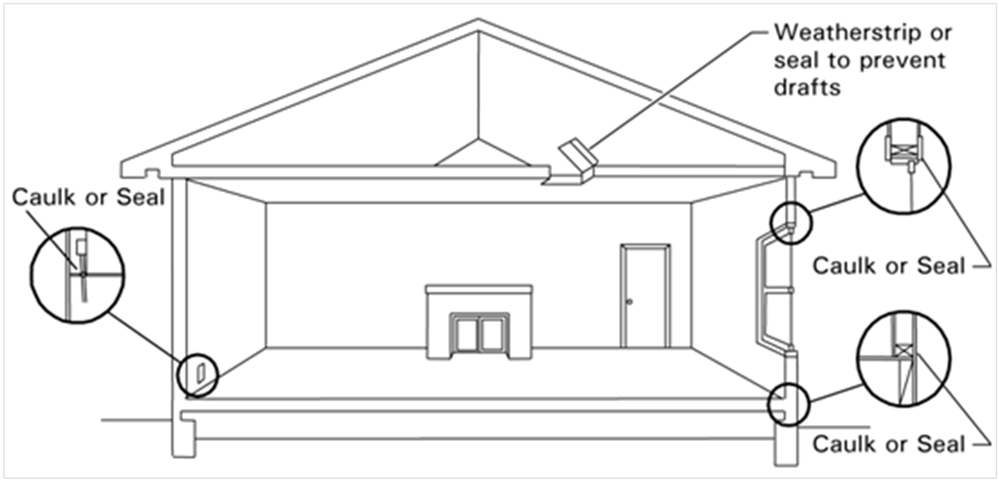
Air leakage through joints, penetrations, cracks, holes and openings around windows, doors, walls, roofs, and floors can result in higher energy use for home heating and cooling than necessary. The following openings in the building envelope shall be caulked, gasketed, weatherstripped, or otherwise sealed:
1. Exterior joints around window and door frames, including doors between the house and garage, between interior HVAC closets and conditioned space, between attic access and conditioned space, between wall sole plates and the floor, exterior panels and all siding materials
2. Openings for plumbing, electricity, and gas lines in exterior and interior walls, ceilings, and floors
3. Openings in the attic floor (such as where ceiling panels meet interior walls, exterior walls, and masonry fireplaces)
4. Openings around exhaust ducts such as those for clothes dryers
5. Weatherstripping is required for all field-fabricated operable windows and doors (other windows and doors must meet infiltration requirements and be laboratory tested). This includes doors between the garage and the house, between interior HVAC closets and conditioned space, and between the attic access and conditioned space (§110.6(b)).
6. All other such openings in the building envelope.
Alternative techniques may be used to meet the mandatory caulking and sealing requirements for exterior walls. These include, but are not limited to:
1. Stucco
2. Caulking and taping all joints between wall components (for example, between slats in wood slat walls
3. Building wraps
4. Rigid wall insulation installed continuously on the exterior of the building
Source: California Energy Commission
Construction Practice/Compliance and Enforcement
The compliance and enforcement process should ensure that all potential sources of infiltration and exfiltration in the building envelope, joints and openings are caulked, gasketed, or otherwise sealed. For more information on Compliance and Enforcement for joints and openings, see Chapter 2.
3.6.1.2 Certification of Insulation Materials
Manufacturers must certify that insulating materials comply with California Quality Standards for Insulating Materials (CCR, Title 24, Part 12, Chapters 12-13), which ensure that insulation sold or installed in the State performs according to stated R-values and meets minimum quality, health, and safety standards. Builders and enforcement agencies shall use the Department of Consumer Affairs Directory of Certified Insulation Material to verify the certification of the insulating material. If an insulating product is not listed in the current edition of the directory, contact the Department of Consumer Affairs, Bureau of Home Furnishing and Thermal Insulation Program, at (916) 999-2041 or by E-mail: HomeProducts@dca.ca.gov.
3.6.1.3 Urea Formaldehyde Foam Insulation
The mandatory measures restrict the use of urea formaldehyde foam insulation. The restrictions are intended to limit human exposure to formaldehyde, a volatile and harmful organic chemical.
If foam insulation is used that has urea formaldehyde, it must be installed on the exterior side of the wall (not in the cavity of framed walls), and a continuous vapor retarder must be placed in the wall construction to isolate the insulation from the interior of the space. The vapor retarder must be 4-mil (0.1 mm) thick polyethylene or equivalent.
3.6.1.4 Flame Spread Rating of Insulation
The California Quality Standards for Insulating Materials requires that exposed facings on insulation material be fire resistant and be tested and certified not to exceed a flame spread of 25 and a smoke development rating of 450. Insulation facings must be in contact with the finished assembly surface or they are considered exposed applications and cannot be installed.
Flame spread ratings and smoke density ratings are shown on the insulation or packaging material or may be obtained from the manufacturer.
3.6.1.5 Insulation Requirements for Heated Slab Floors
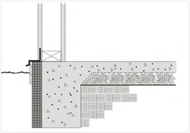
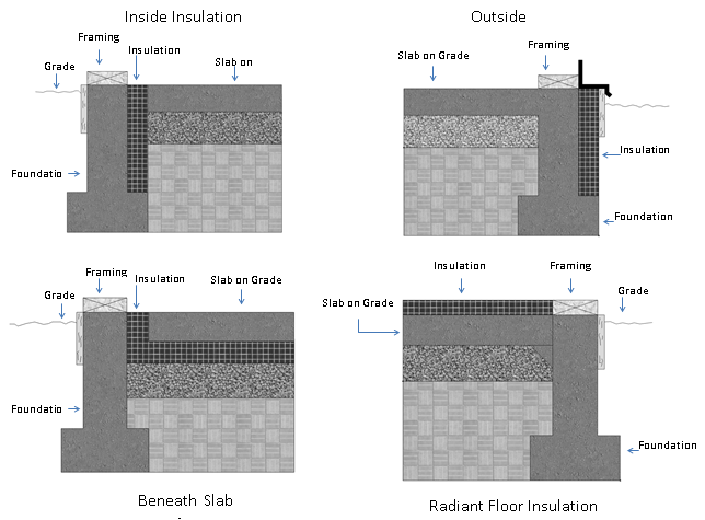
Heated slab-on-grade floors must be insulated according to the requirements in Table 110.8-A and Table 3.4 below. The top of the insulation must be protected with a rigid material to prevent intrusion of insects into the building foundation.
A common location for the slab insulation is on the foundation perimeter (See Figure 3-10). Insulation that extends downward to the top of the footing is acceptable. Otherwise, the insulation must extend downward from the level of the top of the slab, down 16 inches (40 cm) or to the frost line, whichever is greater.
For below-grade slabs, vertical insulation shall be extended from the top of the foundation wall to the bottom of the foundation (or the top of the footing) or to the frost line, whichever is greater.
Another option is to install the insulation between the heated slab and foundation wall. In this case insulation must extend downward to the top of the footing and then extend horizontally inward 4 ft toward the center of the slab. R-5 vertical insulation is required in all climates except climate zone 16, which requires R-10 of vertical insulation and R-7 horizontal insulation.
Source: California Energy Commission
|
Insulation Location |
Insulation Orientation |
Installation Requirements |
Climate Zone |
Insulation R-Value |
|
Outside edge of heated slab, either inside or outside the foundation wall |
Vertical |
From the level of the top of the slab, down 16 inches or to the frost line, whichever is greater. Insulation may stop at the top of the footing where this is less than the required depth. For below grade slabs, vertical insulation shall be extended from the top of the foundation wall to the bottom of the foundation (or the top of the footing) or to the frost line, whichever is greater. |
1 – 15 |
5 |
|
16 |
10 | |||
|
Between heated slab and outside foundation wall |
Vertical and Horizontal |
Vertical insulation from top of slab at inside edge of outside wall down to the top of the horizontal insulation. Horizontal insulation from the outside edge of the vertical insulation extending 4 feet toward the center of the slab in a direction normal to the outside of the building in plan view. |
1 – 15 |
5 |
|
16 |
10 vertical and 7 horizontal |
3.6.1.6 Wet Insulation Systems
Wet insulation systems are roofing systems where the insulation is installed above the waterproof membrane of the roof. Water can penetrate this insulation material and affect the energy performance of the roofing assembly in wet and cool climates. In Climate Zones 1 and 16, the insulating R-value of continuous insulation materials installed above the waterproof membrane of the roof must be multiplied by 0.8 and using the result value in choosing the table column in Reference Joint Appendix JA4 for determining assembly U-factor (when using the Joint Appendix JA4 table to comply). See the footnotes for Tables 4.2.1 through 4.2.7 in the Reference Joint Appendix JA4.
3.6.1.7 Roofing Products Solar Reflectance & Thermal Emittance
Roofing products shall be rated by the Cool Roof Rating Council (CRRC) and labeled appropriately by the roofing manufacturer for both solar reflectance and thermal emittance. The CRRC certification includes solar reflectance and thermal emittance. There are three kinds of solar reflectance:
1. Initial solar reflectance.
2. Three-year aged solar reflectance.
3. Accelerated aged solar reflectance.
All requirements of the Energy Standards are based on the three-year aged reflectance. However, if the aged value for the reflectance is not available in the CRRC’s Rated Product Directory, then the aged value shall be derived from the CRRC aged value equation (using the initial value for solar reflectance) or an accelerated process. Until the appropriate aged rated value for the reflectance is posted in the directory, the equation below can be used to calculate the aged rated solar reflectance or a new method of testing is used to find the accelerated solar reflectance.
Equation 3-2:
Aged Reflectancecalculated=(0.2+ β[ρinitial – 0.2])
Where:
ρinitial = Initial Reflectance listed in the CRRC Rated Product Directory
β = soiling resistance which is listed in Table 3-5
|
PRODUCT TYPE |
β |
|
Field-applied coating |
0.65 |
|
Other |
0.70 |
The Energy Standards do not distinguish between initial and aged thermal emittance, meaning that either value can be used to demonstrate compliance with the Energy Standards. If a manufacturer fails to obtain CRRC certificate for its roofing products, the following default aged solar reflectance and thermal emittance values must be used for compliance:
1. For asphalt shingles, 0.08/0.75
2. For all other roofing products, 0.10/0.75

A. Field Applied Liquid Coatings
There are several liquid products, including elastomeric coatings and white acrylic coatings, that qualify for field-applied liquid coatings. The Energy Standards specify minimum performance and durability requirements for field-applied liquid coatings. These requirements do not apply to industrial coatings that are factory-applied, such as metal roof panels. The requirements address elongation, tensile strength, permeance, and accelerated weathering. The requirements depend on the type of coating and are described in greater detail below. Liquid roof coatings applied to low-sloped roofs in the field as the top surface of a roof covering shall comply with the following mandatory requirements and descriptions.
a. Aluminum-Pigmented Asphalt Roof Coatings
Aluminum-pigmented coatings are silver-colored coatings that are commonly applied to modified bitumen and other roofing products. The coating has aluminum pigments that float to the top surface of the coating while it is setting, providing a shiny and reflective surface. Because of the shiny surface and the physical properties of aluminum, these coatings have a thermal emittance below 0.75, which is the minimum rating for prescriptive compliance.
This class of field-applied liquid coatings shall be applied across the entire surface of the roof and meet the dry mil thickness or coverage recommended by the coating manufacturer, considering the substrate on which the coating will be applied. Also, the aluminum-pigmented asphalt roof coatings shall be manufactured in accordance with ASTM D2824. Standard specification is also required for aluminum-pigmented asphalt roof coatings, nonfibered, asbestos-fibered, and fibered without asbestos that are suitable for application to roofing or masonry surfaces by brush or spray; and installed in accordance with ASTM D3805, Standard Guide for Application of Aluminum-Pigmented Asphalt Roof Coatings.
b. Cement-Based Roof Coatings
This class of coatings consists of a layer of cement and has been used for a number of years in California’s Central Valley and other regions. These coatings may be applied to almost any type of roofing product.
Cement-based coatings shall be applied across the entire roof surface to meet the dry mil thickness or coverage recommended by the manufacturer. Also, cement-based coatings shall be manufactured to contain no less than 20 percent Portland cement and meet the requirements of ASTM D822, ASTM C1583 and ASTM D5870.
c. Other Field-Applied Liquid Coatings
Other field-applied liquid coatings include elastomeric and acrylic-based coatings. These coatings must be applied across the entire roof surface to meet the dry mil thickness or coverage recommended by the coating manufacturer, taking into consideration the substrate on which the coating will be applied. The field-applied liquid coatings must be tested to meet several performance and durability requirements as specified in Table 110.8-C of the Energy Standards or the minimum performance requirements of ASTM C836, D3468, or D6694, whichever are appropriate to the coating material.
3.6.1.8 Radiant Barriers
The radiant barrier is a reflective material that reduces radiant heat transfer caused by solar heat gain in the roof. Radiant barriers are installed below the roof deck in the attic and reduce radiant heat to air distribution ducts and insulation located below the radiant barrier. To qualify, a radiant barrier must have an emittance of 0.05 or less. The product must be tested according to ASTM C-1371-10 or ASTM E408-13(2013) and must be certified by the California Bureau of Electronic and Appliance Repair, Home Furnishings and Thermal Insulation and listed in its Consumer Guide and Directory of Certified Insulation material, at www.bhfti.ca.gov/industry/tinsulation.shtml.
3.6.1.9 Ceiling and Attic Roof Insulation
Wood-framed roof/ceiling construction assemblies must have at least R-22 insulation or a maximum U-factor of 0.043 based on 16 inch on center wood framed rafter roofs, as determined from the Appendix JA4. Some areas of the roof/ceiling can be greater than the maximum U-factor as long as other areas have a U-factor lower than the requirement and the weighted average U-factor for the overall ceiling/roof is 0.043 or less.
Metal-framed and roof/ceiling constructions other than wood framed must have a U-factor of 0.043 or less to comply with the mandatory measures. If the insulation is not penetrated by framing, such as rigid insulation laid over a structural deck, then the rigid insulation can actually have a rated R-value of less than R-22 so long as the total roof/ceiling assembly U-factor is not greater than U-0.043.
3.6.1.10 Loose Fill Insulation
Loose fill insulation must be blown in evenly, and insulation levels must be documented on the certificate of installation (CF2R). The insulation level can be verified by checking that the depth of insulation conforms to the manufacturer’s coverage chart for achieving the required R-value. The insulation must also meet the manufacturer’s specified minimum weight per ft² for the corresponding R-value. When installing loose fill insulation, the following guidelines should be followed:
1. For wood trusses that provide a flat ceiling and a sloped roof, the slope of the roof should be 4:12 or greater to provide adequate access for installing the insulation. Insulation thickness near the edge of the attic will be reduced with all standard trusses, but this is acceptable as long as the average thickness is adequate to meet the minimum insulation requirement.
2. If the ceiling is sloped (for instance, with scissor trusses), loose fill insulation can be used as long as the slope of the ceiling is no more than 4:12. If the ceiling slope is greater than 4:12, loose fill should be used only if the insulation manufacturer will certify the installation for the slope of the ceiling.
3. At the apex of the truss, a clearance of at least 30 inch should be provided to simplify installation and inspection.
3.6.1.11 Wall Insulation
The mandatory measures have two requirements depending on frame size:
1. 2x4 inch wood-framed walls above grade shall have at least R-13 insulation installed in the cavities between framing members, or a U-factor that cannot exceed U-0.102. Insulation may be of greater insulating value in certain areas of the wall and of lesser insulating value in other areas of the wall provided that the area-weighted U- factor does not exceed 0.102 to show equivalence to an R-13 wall.
2. 2x6 inch or greater wood-framed walls above grade shall have at least R-19 insulation installed in the cavities between framing members or a U-factor not exceeding 0.074. Insulation may be of greater insulating value in certain areas of the wall and of lesser insulating value in other areas of the wall provided that the area-weighted U-factor does not exceed 0.074 to show equivalence to an R-19 wall.
There are several cases where the mandatory measures for wall insulation do not apply or apply in a special way. For best practice, the following should be implemented:
1. The mandatory measures apply to framed foundation walls of heated basements or heated crawl spaces that are located above grade, but not to the portion that is located below grade.
2. For additions to existing buildings, existing wood-framed walls that are already insulated with R-11 insulation need not comply with the mandatory R-13 wall insulation.
3. Rim joists between floors of a multistory building are deemed to comply with these mandatory measures if they have R-13 insulation installed on the inside of the rim joist and are properly installed between intersecting joist members.
Demising partitions and knee walls are not required to meet the prescriptive requirements of §150.1(c)1B Demising partitions and knee walls are required to meet the mandatory minimum insulation requirement as set in §150.0(c)1 and §150.0(c)1 requiring that insulation not less than R-13 be installed between a 2x4 framing, or a U-factor that shall not exceed U-0.102. §150.0(c)2 requires insulation not less than R-19 be installed in framing of 2x6 inch or greater, or a U-factor equal to or less than 0.074.
3.6.1.12 Raised-Floor Insulation
Wood-framed floors must have at least R-19 insulation installed between framing members, or the construction must have a U-factor of 0.049 or less. The equivalent U-factor is based on R-19 insulation in a 2x6, 16 inch on center wood-framed floor without a crawl space. The R-19 insulation value and U-factor of U-0.049 are for the floor assembly alone and do not assume the effects of a crawlspace or buffer zone beneath the floor. If comparing to a crawlspace assembly, the equivalent U-factor is 0.037, which includes the effect of the crawlspace.
Other types of raised floors, except for concrete raised floors (concrete raised floors do not have a mandatory requirement, but do have a prescriptive requirement) must also meet the maximum U-factor. In all cases, some areas of the floor can have a U-factor greater than the requirement as long as other areas have a U-factor that is lower than the requirement and the area-weighted average U-factor is less than that described above.
Raised slab floors with radiant heat (heated slab floors) must meet special insulation requirements that are described in Chapter 4 of this 'manual.
When a controlled ventilated or an unvented crawlspace is used, raised-floor insulation is not required, although vapor retarder is required over the ground, and the foundation walls must be insulated
3.6.1.13 Fireplaces, Decorative Gas Appliances and Gas Logs
The Energy Standards have mandatory requirements to limit infiltration associated with fireplaces, decorative gas appliances, and gas logs. Fireplace efficiency can be greatly improved through proper air control. Reduced infiltration is also a benefit when the fireplace is not operating (the majority of the time for most homes).
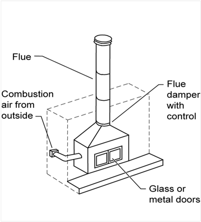
Installation of factory-built or masonry fireplaces (see Figure 3-12) must include:
1. Closable metal or glass doors covering the entire opening of the firebox that can be closed when the fire is burning.
2. A combustion air intake that is at least 6 square inches to draw air from outdoors and equipped with a readily accessible, operable, and tight-fitting damper or combustion air control device (Exception: An outside combustion air intake is not required if the fireplace is installed over a concrete slab and the fireplace is not located on an exterior wall.)
3. A flue damper with a readily accessible control. (Exception: When a gas log, log lighter, or decorative gas appliance is installed in a fireplace, the flue damper shall be blocked open if required by the manufacturer's installation instructions or the California Mechanical Code.)
Continuously burning pilot lights are prohibited for fireplaces as well as for decorative gas appliances and gas logs. In 'addition, indoor air may not be used for cooling a firebox jacket when that indoor air is vented to the outside of the building.
When a gas log, log lighter or decorative gas appliance is installed in a fireplace, the flue damper must be blocked open if required by the manufacturer's installation instructions or the California Mechanical Code.
Equipment certified to the Energy Commission as a gas space heater may have a continuously burning pilot light.
Source: California Energy Commission
Example 3-15
Question:
If I want to have a gas log or some other device in the fireplace of my home, can I have a standing pilot light? Can I block open the damper?
Answer:
The Energy Standards disallow standing pilot lights. The flue damper may be blocked open if required by either the manufacturer's installation instructions or the California Mechanical Code.
Example 3-16
Question:
§150.0(e)2 states that no fireplace, decorative gas appliance or gas log can be installed if it has a
continuously burning pilot light. The California Mechanical Code requires all gas appliances installed in California to have a manually operated shut-off valve, accessible to the inhabited space. Does this shut-off valve meet the intent of this section?
Answer:
Not if the pilot light must be manually extinguished when the appliance is off. A unit that meets the intent of this section will have a pilot light that cannot stay on when the unit is off.
Example 3-17
Question:
A building plan specifies a freestanding gas heater that is decorative; however, the equipment is vented and is rated as a room heater. Is it acceptable that this appliance have a pilot light?
Answer:
Yes. Since this equipment is rated as a room heater, it can have a continuous burning pilot light.
Example 3-18
Question:
Do decorative gas appliances need glass or metal doors?
Answer:
Yes, the door requirement applies to masonry or factory-built fireplaces only. If a decorative gas appliance is installed inside a fireplace, the fireplace needs doors. Consult with the manufacturer of the decorative gas appliance regarding combustion air requirements.
3.6.1.14 Slab Insulation
§150.0(f) §118(g)
The mandatory requirements state that the insulation material must be suitable for the application, with a water absorption rate no greater than 0.3 percent when tested in accordance with ASTM C272 Test Method A, 24-Hour immersion, and a vapor permeance no greater than 2.0 perm/inch when tested in accordance with ASTM E96. An example of an insulating material that meets these specifications is smooth-skin extruded polystyrene.
The insulation must also be protected from physical and UV degradation by either installing a water-resistant protection board, extending sheet metal flashing below grade, choosing an insulation product that has a hard durable surface on one side, or by other suitable means.
3.6.1.15 Vapor Retarder
Vapor retarder class is a measure of the ability of a material or assembly to limit the amount of moisture that passes through the material or assembly. Vapor retarder classes are defined in Section 202 of the CBC. Testing for vapor retarder class is defined using the desiccant method of ASTM E96.
1. Class I: 0.1 perm or less
2. Class II: 0.1 < perm < 1.0 perm
3. Class III: 1.0 < perm < 10 perm
In Climate Zones 14 and 16, a continuous Class I or Class II vapor retarder, lapped or joint sealed, must be installed on the conditioned space side of all insulation in all exterior walls, on the roof decks of vented attics with above-or below-deck air-permeable insulation, and in unvented attics with air-permeable insulation.
Buildings with unvented crawl spaces in Climates Zones 1-16 must have a Class I or Class II vapor retarder covering the earth floor to protect against moisture condensation.
If a building has a controlled-ventilation crawl space, a Class I or Class II vapor retarder must be placed over the earth floor of the crawl space to reduce moisture entry and protect insulation from condensation in accordance with RA4.5.1.
There are many product types having tested vapor retarder performance. Some common examples are the following:
1. Foil and other facings on gypsum board can provide moisture resistance, and product literature should always be checked to ensure conformance to ASTM E96.
2. The kraft paper used as facing on thermal batt insulation material is typically a Class II vapor retarder. Faced batts may have flanges for fastening to assembly framing. Fastening flanges may be face- or inset-stapled or not stapled at all, as the flanges provide no moisture control. Face stapling of flanged thermal batts helps ensure the insulation material is installed fully and properly within the framed cavity. Flangeless batts are also common and require no fastening as these materials maintain installation integrity through friction-fitting within the cavity of framed assemblies. In all cases, the insulation must be installed properly.
3. Many interior painted surfaces may also qualify for meeting the vapor retarder requirement if the paint product has been tested to show compliance as a vapor retarder. The effectiveness of vapor retarder paint depends upon the installed thickness (in mils). These products often require more than one layer to achieve the tested perm rating, and care must be shown by the installer of the paint and for inspection by the building official.
4. Closed-cell spray polyurethane foam (ccSPF) products can provide Class I or Class II vapor retarder performance, depending on thickness.
For all types of vapor retarders, care should be taken to seal penetrations, such as electric outlets on exterior walls.

3.6.1.16 Recessed Luminaires in Ceilings
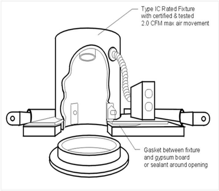
Luminaires recessed in insulated ceilings can create thermal bridging through the insulation. Not only does this degrade the performance of the ceiling assembly, but it can permit condensation on a cold surface of the luminaire if exposed to moist air, as in a bathroom.
For these reasons, luminaires recessed in insulated ceilings must meet three requirements:
1. They must be listed as defined in the Article 100 of the California Electric Code for zero clearance insulation contact (IC) by Underwriters Laboratories or other testing/rating laboratories recognized by the International Code Council (ICC). This enables insulation to be in direct contact with the luminaire.
2. The luminaire must have a label certified as per §150.0(k)1Cii for airtight (AT) construction. Airtight construction means that leakage through the luminaire will not exceed 2.0 cfm when exposed to a 75 Pa pressure difference, when tested in accordance with ASTM E283.
3. The luminaire must be sealed with a gasket or caulk between the housing and ceiling.
Refer to the Lighting chapter (Chapter 6) of this compliance 'manual for more information regarding the applicable requirements for recessed luminaires.
Source: California Energy Commission
3.6.1.17 Ventilation for Indoor Air Quality
All buildings shall meet the requirements of ASHRAE Standard 62.2, Ventilation and Acceptable Indoor Air Quality in Low-Residential Buildings. The whole-building ventilation airflow shall be provided to meet the requirements of ASHRAE 62.2. Window operations are not a permissible method for providing whole house ventilation. Use of a continuously operating central fan integrated with a forced-air system air handler cannot be used to meet the whole-building ventilation airflow requirement.
3.6.1.18 Ventilation Openings
ASHRAE Standard 62.2 requires ventilation openings in habitable spaces, toilets and utility rooms. Spaces that meet the exhaust requirements are exempted from meeting the whole-building ventilation air flow requirement; therefore, an exhaust system can be substituted for a ventilation opening (See Section 4.6.6).
Field verification and diagnostic testing is required to confirm proper ventilation airflow following the procedures specified in the Appendix RA3.7.
3.6.2.1 Roof/Attic
The 2016 Energy Standards are designed to offer flexibility to the builders and designers of residential new construction in terms of achieving the intended energy efficiency targets. As such, the Energy Standards offer several options for achieving one of two design objectives related to improving energy performance of homes built with ventilated attics in Climate Zones 4, 8-16 as shown in Figure 3-15.
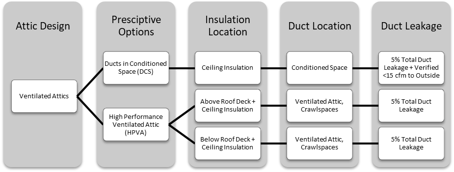
High-Performance Ventilated Attic (HPVA) implements measures that minimize temperature difference between the attic space and the conditioned air being transported through ductwork in the attic. The package consists of insulation either below the roof deck or insulation above the roof deck in addition to insulation at the ceiling, R-8 ducts, and 5 percent total duct leakage of the nominal air handler airflow.
Ducts in Conditioned Space (DCS) locates ducts and air handlers in the thermal and air barrier envelope of the building. The Ducts in Conditioned Space option requires field verification to meet the prescriptive requirement.
Note: All the prescriptive requirements for HPVA or DCS are based on the assumption that the home is built with the following construction practices:
A. The attic is ventilated with appropriate free vent area as described in Section 3.6.2.1(E).
B. The roof is constructed with standard wood rafters and trusses.
C. The outermost layer of the roof construction is either tiles or shingles.
D. The air handler and ducts are in the ventilated attic for HPVA and are in conditioned space for DCS.
E. The air barrier is located at the ceiling (excludes “cathedral” roof/ceiling systems).
If a building design does not meet all of these specifications, it must comply through the performance approach.
Example 3-19
Question:
If 5 percent of a roof will be a cathedral ceiling, can it still comply under the prescriptive requirements?
Answer:
No. The entire attic must be a ventilated space with the building air barrier located at the ceiling with standard wood rafter trusses to comply with the prescriptive requirements. This project must comply through the performance approach.
Example 3-20
Question:
Does a sealed (unventilated) attic with insulation at the roof deck comply under the prescriptive requirements?
Answer:
No. The entire attic must be a ventilated space with the building air barrier located at the ceiling with standard wood rafter trusses to comply with the prescriptive requirements. This project must comply through the performance approach.
A. Roof/Ceiling Insulation
This section describes the requirements and approaches necessary to meet the requirements for the HPVA as they relate to roof/ceiling insulation. HVAC aspects of the HPVA including duct insulation and duct leakage are described in Section 4. Requirements and approaches to meet the Ducts in Conditioned Space (DCS) are also described in Section 4 of this manual.
§150.1(c).1 requires different values of roof/ceiling insulation, depending on whether the HPVA (option A or B) or DCS (option C) is chosen as described in Figure 3-16.
The standard design in the performance approach is based on Option B, as detailed in 1 of Figure 3-17, installed with a tile roof.
|
Strategy |
How to Comply | |
|
High-Performance Ventilated Attics | ||
|
Option A |
Vented attic with continuous insulation applied above the roof deck. (Figure 3-18). Ceiling insulation required separately above finished attic ceiling. |
Table 150.1-A of the Energy Standards Roof Assembly Option A |
|
Option B |
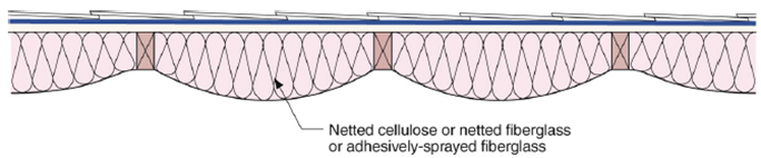
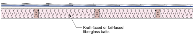
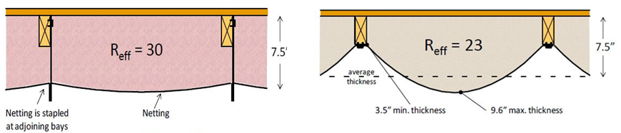
Vented attic with batt, spray in cellulose/fiberglass secured with netting, or SPF. (Figure 3-18). Ceiling insulation required separately above finished attic ceiling. |
Table 150.1-A of the Energy Standards Roof Assembly Option B |
|
Ducts in Conditioned Space | ||
|
Option C |
Vented attic with no insulation at roof deck. Ceiling insulation required separately above finished attic ceiling. Ducts and air handler equipment in conditioned space that is NOT a sealed attic. |
Table 150.1-A of the Energy Standards Roof Assembly Option C Form: CF2R-MCH-20b |
|
Option A (CZ 4, 8-16) |
Option B1 (CZ 4, 8-16) |
Option C (CZ 4, 8-16) |
|
¨ Vented attic ¨ R6 (air space) or R8 (no air space) continuous above deck rigid foam board insulation ¨ R38 ceiling insulation ¨ Radiant Barrier ¨ R8 duct insulation ¨ 5% total duct leakage |
¨ Vented attic ¨ R13 (air space) or R15 (no air space) batt, spray in cellulose/fiberglass below roof deck secured with netting, or SPF ¨ R38 ceiling insulation ¨ R8 duct insulation ¨ 5% total duct leakage |
¨ Vented attic ¨ R30 or R38 ceiling insulation (climate zone specific) ¨ R6 or R8 ducts (climate zone specific) ¨ Radiant Barrier ¨ Verified ducts in conditioned space |
|
1 Standard Design used to set the energy budget for the Performance Approach. | ||

Source: Building Science Corporation
Option A requires insulation above the roof rafters, directly in contact with the roof deck, while Option B requires insulation installed between the roof rafters. The insulation values are different depending on whether there is an air gap present between the roofing materials and the roof deck. For roof constructions with an air gap present, which is standard for concrete or clay tile, R6 insulation is required above the roof rafters or R13 below the roof deck placed between the rafters. If there is no air gap present between the roofing and roof deck, R8 insulation is required above the roof rafter or R18 below the roof deck placed between the rafters.
The R-values for insulation installed above the roof rafters are lower than the R-values for insulation installed below the roof deck due to the added benefit of reduced thermal bridging when continuous insulation is applied to the roof deck. Further, when an air space is present between the roofing and the roof deck, the effect of insulation is greater than when there is no air space.
Standard residential roof construction practice in California for concrete/clay tiles is to have an air gap between the tiles and roof deck. For asphalt shingles, the practice is to place the roofing material directly on top of the roof deck without an air gap. It is, however, possible for builders to construct different construction assemblies than these standard assemblies such as providing air gaps between the asphalt shingles and roof deck through construction techniques explained later in this document.
The prescriptive requirement for roof deck insulation can also be met by placing ducts in conditioned space and getting HERS verification (Option C). The requirements to comply with Option C are explained in Chapter 4 of this manual.
Construction Practice/Compliance and Enforcement
1. Above-Roof Rafter Insulation (Option A):
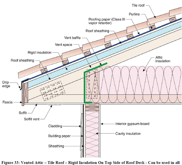
In a vented attic, rigid board insulation can be installed above the roof rafters to add value to the thermal integrity of the roof system. As described above, the prescriptive insulation value depends on whether an air gap is present above the rigid insulation. Above-rafter insulation can be implemented with either asphalt shingles or clay/concrete tiles. Check manufacturer’s specifications for proper nail schedules (fastening patterns); this will change depending on the roof pitch, truss spacing, and roofing material. When above-rafter insulation is installed, a radiant barrier must also be installed in the required climate zones.

Source: California Energy Commission
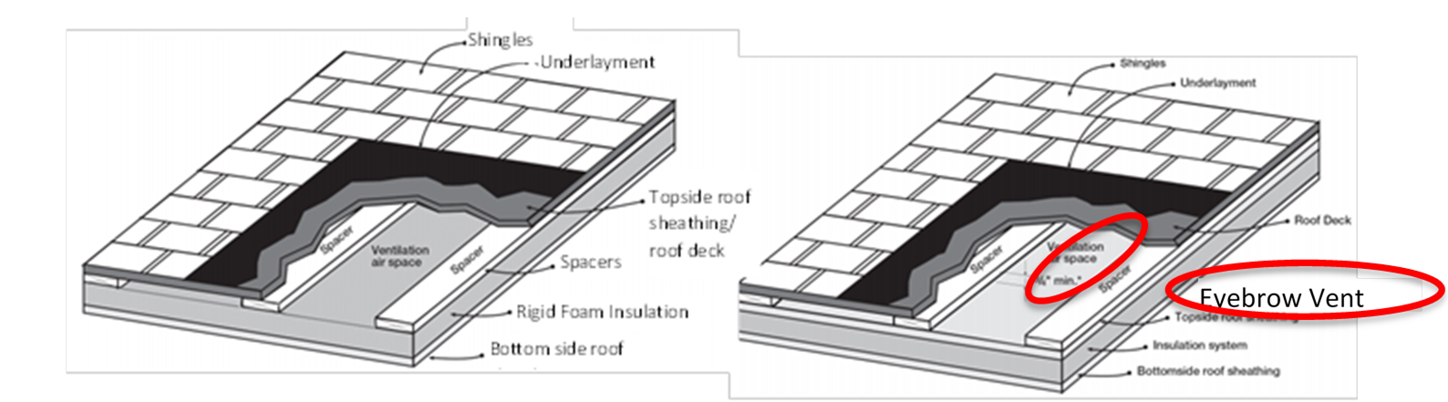
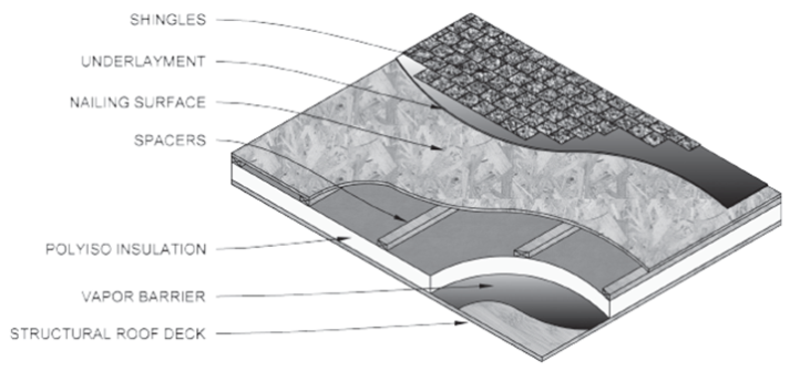
Figure 3-20: Above Deck Insulation With Spacers Installed With and Without Top Sheathing
Source: ARMA technical bulletin No. 211-RR-94
Source: PIMA Tech Bulletin #106
Source: Building Science Corporation
If the air gap is not desired, there are insulation products available that can fit directly under concrete/clay or steel tile, as shown in the figure below.
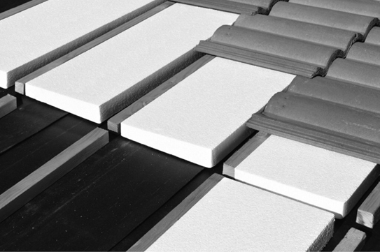
Source: Wedge-It
Example 3-21
Question:
A project plans to install R8 rigid foam insulation above the roof deck using two R4 foam boards. Can this method be used to meet the prescriptive requirements? If so, are there best practices for installing the two layers of insulation?
Answer:
Yes, installing two R4 rigid foam board layers meets the R8 prescriptive requirement. (Remember that R8 is required when there is no air gap between insulation and roofing materials, but R6 is required if there is air gap.) To prevent water infiltration, it is best to stagger the horizontal and vertical joints of the two layers and take care to seal each joint properly.
Source: Building Science Corporation
Example 3-22
Question:
A project plans to install R6 rigid foam insulation above the roof deck with roofing material placed directly over the insulation; does this meet the prescriptive requirements? Are there best practices for installing the insulation?
Answer:
No, this construction does not comply with the prescriptive requirements. R6 insulation can be used only above the roof deck when there is an air gap between the insulation and the finishing roofing material. Using spacers or battens (purlins) are two strategies to create this air gap. Products exist that combine insulation, spacers, and an additional sheathing for nailing asphalt shingles, check with insulation manufacturers for available products. Refer to the best practices above in the Above Roof Deck Insulation section. Alternatively, R8 insulation can be installed if no air gap is desired.
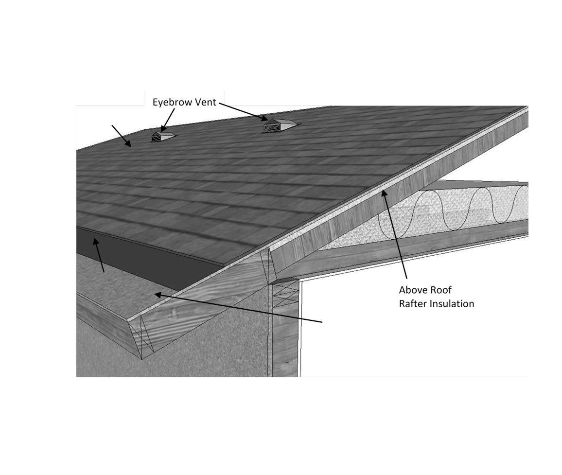
Addressing Attic Ventilation With Above-Deck Insulation
Proper attic ventilation occurs at two points at the roof: the soffit (or eave) vents and the ridge (or eyebrow) vents. Ridge or eyebrow venting must be maintained when installing above-deck insulation, as shown in Figure 3-26.
Example 3-23
Question:
Does a roof assembly using above deck insulation meet Class A/B/C fire rating specifications, as determined by California Building Code, Chapter 15?
Answer:
Application of above-deck insulation affects the fire rating classification of roof covering products. Roof covering products are currently rated to class A/B/C based on the ASTM E108 (NFPA 256, UL790) test. Class A/B/C ratings are done with specific roof assemblies, and ratings are valid only when the installation is the same as the assembly as rated. Under current building code requirement, tile roof products installed directly over the roof deck or over purlins are automatically rated Class A. Chapter 15 in the California Building Code (and International Building Code section 1505 for Fire Classification) specify that certain roofing materials are Class A without having to test to ASTEM E108. These materials include slate, clay, concrete roof tile, an exposed concrete roof deck, and ferrous and copper shingles; however, asphalt shingles are not covered under this category.
Insulation products, on the other hand, are subject to a different fire test from roof-covering products. California Building Code and International Building Code (Section 2603 for Foam Plastic Insulation) require foam plastic insulation to be tested to demonstrate a flame-spread index of not more than 75 and a smoke-developed index of not more than 450 according to ASTM E84 [UL723]. The requirements are applicable to roof insulation products, including XPS/polyiso/polyurethane above‐deck insulation and SPF below‐deck insulation products.
To ensure that roof assemblies with insulation meet the proper fire rating classification, roof product manufacturers and insulation manufacturers must test and develop assemblies that meet the CBC testing specifications.
2. Below-Deck Insulation (Option B):
In a vented attic, air-permeable or air-impermeable insulation (that is, batt, spray foam, loose-fill cellulose, or fiberglass) should be placed directly below the roof deck between the truss members and secured in place to provide a thermal barrier for the attic space. This is especially useful when ducts and equipment are present. Insulation must be in direct contact with the roof deck and secured by the insulation adhesion, facing, mechanical fasteners, wire systems, a membrane material, or netting.
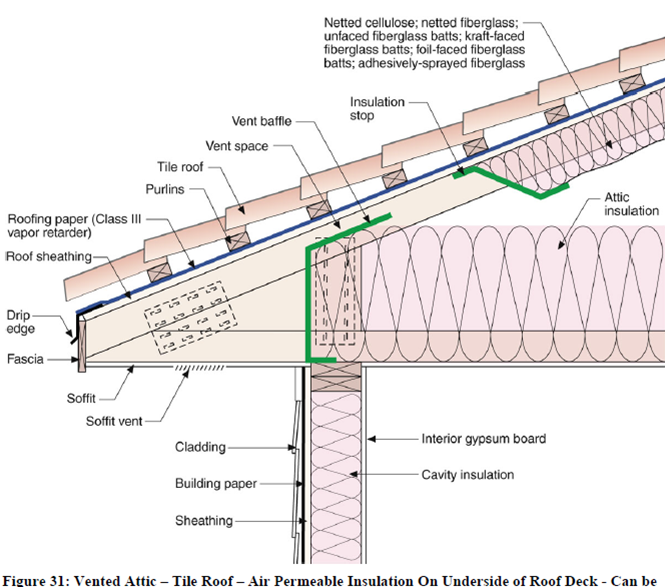
Proper attic ventilation must always be maintained to prevent the potential for moisture to condense. In Climate Zones 14 and 16, a Class I or Class II vapor retarder must also be used to manage moisture, as stated in California Residential Code Section R806.2. See Figure 3-24 through Figure 3-27 for depictions of insulation options and maintaining proper ventilation. More information on best practices to maintain proper attic ventilation is discussed below.

Source: California Energy Commission
")
Source: Building Science Corporation
When insulation is installed below the roof deck to meet the prescriptive requirements, a radiant barrier is not required. However, a draped radiant barrier may be installed to receive performance credit.
Addressing Attic Ventilation With Below-Deck Insulation
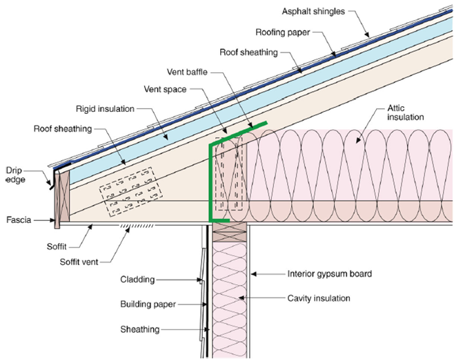
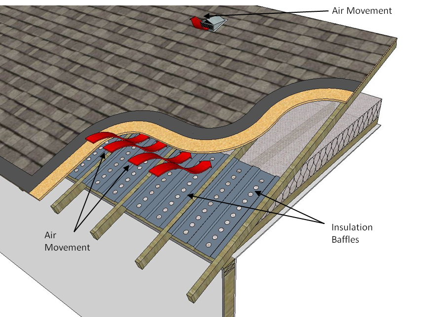
When installing insulation below the roof deck, vent baffles and insulation stoppers can be used to maintain proper ventilation space, as shown in Figure 3-27. Proper flow of air through the space helps remove moisture and prevents any associated issues.
Source: Building Science Corporation
Example 3-24
Question:
A new construction project in Climate Zone 12 with HVAC ducts in the attic was designed to meet the prescriptive requirements for roof deck and ceiling insulation. Due to miscommunication amongst the team, however, the roof deck insulation was not installed, and R-49 ceiling insulation was installed instead. Does this project still comply?
Answer:
This project no longer meets the prescriptive requirements and must follow the performance approach. For future projects, clearly communicating the project expectations to all team members early in the construction process is key to succeeding at this design strategy. Having a project initiation meeting with all subcontractors and team members is a best practice, at least for the first few projects, until the entire team is aware of the design needs.
Note: If the design was changed so that the roof deck has a radiant barrier and the HVAC equipment and ducts are verified to be in conditioned space, the altered design will meet the prescriptive requirements under Option C.
3. Duct and Air Handlers Located in Conditioned Space (Option C):
Option C allows a project to place and verify that ducts are located in conditioned space instead of installing insulation at the roof deck. If complying with this path, ceiling and duct insulation must be installed at the values specified in Table 150.1-A for Option C, and a radiant barrier is also required in some climate zones. Simply locating ducts in conditioned space does not qualify for this requirement; a HERS Rater must test and verify the system and that the ducts are insulated to a level required in Table 150.1-A of the Energy Standards.
Design strategies that can be used to prescriptively comply with Option C include dropped ceilings (dropped soffit), plenum or scissor truss to create a conditioned plenum box, and open-web floor truss. The key is that the ducts and equipment are placed within the air barrier of the building. See Section 4.4.2 for detailed information on DCS strategies.
B. Ceiling Insulation
Insulation coverage should extend far enough to the outside walls to cover the bottom chord of the truss. However, insulation should not block eave vents in attics because the flow of air through the attic space helps remove moisture that can build up in the attic and condense on the underside of the roof. (See Figure 3-27.) This can cause structural damage and reduce the effectiveness of the insulation.
Based on area-weighted averaging, ceiling insulation may be tapered near the eave, but it must be applied at a rate to cover the entire ceiling at the specified level. An elevated truss is not required but may be desirable. See Section 3.6.3.1(C) for details.
C. Radiant Barriers
The prescriptive requirements call for a radiant barrier in Climate Zones 2 through 15 except when below-deck insulation is installed. The radiant barrier is a reflective material that reduces radiant heat transfer caused by solar heat gain in the roof. Radiant barriers reduce the radiant gain to air distribution ducts and insulation located below the radiant barrier, typically within the attic space. In the performance approach, radiant barriers are modeled as separate adjustments to the heating U-factor and the cooling U-factor. The duct efficiency is also affected by the presence of a radiant barrier when using the performance approach.
Construction Practice
A radiant barrier must have a tested emissivity of 0.05 or less. The most common way of meeting the radiant barrier requirement is to use roof sheathing that has a radiant barrier bonded to it by the manufacturer. Some oriented strand board (OSB) products have a factory-applied radiant barrier. The sheathing is installed with the radiant barrier (shiny side) facing down toward the attic space. Alternatively, a radiant barrier material that meets the same ASTM test and moisture perforation requirements that apply to factory-laminated foil can be field-laminated. Field lamination must use a secure mechanical means of holding the foil type material to the bottom of the roof decking such as staples or nails that do not penetrate all the way through the roof deck material. Roofs with gable ends must have a radiant barrier installed on them to meet the radiant barrier requirement.
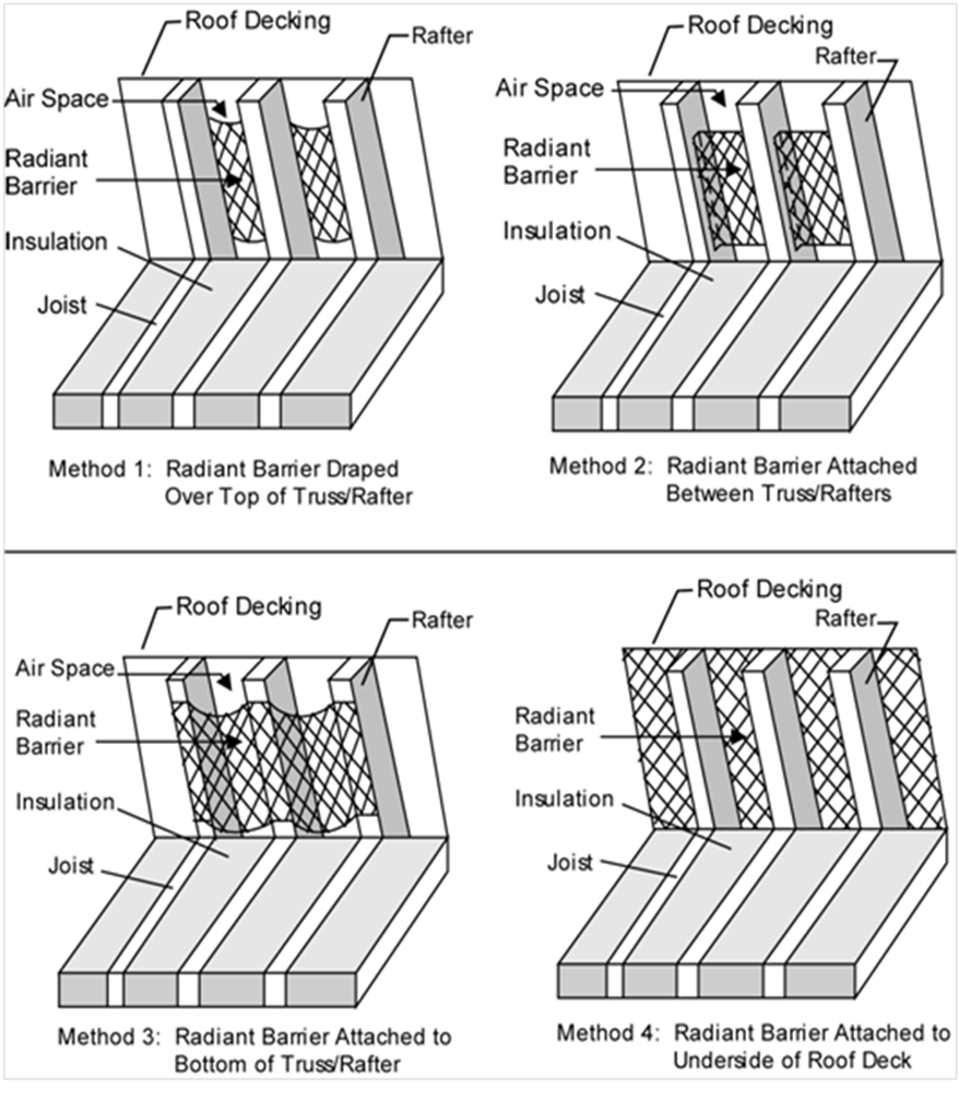
Other acceptable methods are to drape a foil type radiant barrier over the top of the top chords before the sheathing is installed, stapling the radiant barrier between the top chords after the sheathing is installed, and stapling the radiant barrier to the underside of the truss/rafters (top chord). For these installation methods, the foil must be installed with spacing requirements as described in Residential Reference Appendices RA4.2.1. Installation of radiant barriers is somewhat more challenging in the case of closed rafter spaces, particularly when roof sheathing is installed that does not include a laminated foil type radiant barrier. Radiant barrier foil material may be field-laminated after the sheathing has been installed by “laminating” the foil as described above to the roof sheathing between framing members. This construction type is described in the Residential Reference Appendices RA4.2.1.1. See below for drawings of radiant barrier installation methods.
Source: California Energy Commission
D. Roofing Products (Cool Roof)
Cool roofs of steep and low-sloped roofs are required in some climate zones. A low-slope roof is defined as a surface with a pitch less than or equal to 2:12 (9.5 degrees from the horizontal or less) while a steep-slope roof is a surface with a pitch greater than 2:12 (more than 9.5 degrees from the horizontal). The prescriptive requirement is based on an aged solar reflectance and thermal emittance tested value from the Cool Roof Rating Council (CRRC).
For projects using the prescriptive compliance path, an alternative to the aged solar reflectance and thermal emittance is to use the Solar Reflectance Index (SRI) to show compliance. A calculator has been produced to calculate the SRI by designating the solar reflectance and thermal emittance of the desired roofing material. The calculator can be found at www.energy.ca.gov/title24/2013standards. To calculate the SRI, the 3-year aged value of the roofing product must be used. By using the SRI calculator a cool roof may comply with an emittance lower than 0.85, as long as the aged reflectance is higher and vice versa.
The residential roofing product requirement in the prescriptive package is as follows:
1. For steep-sloped applications in Climate Zones 10-15, the three year aged solar reflectance minimum is 0.20 and the (three-year aged or initial) thermal emittance minimum is 0.75, or a minimum solar reflectance index (SRI) of 16.
2. For low-sloped roofing applications in Climate Zones 13 and 15, there is a minimum aged solar reflectance of 0.63 and thermal emittance of 0.75, or a minimum SRI of 75.
There are two exceptions to meeting the roofing products requirements in the prescriptive package:
1. The roof area with building integrated photovoltaic panels and building integrated solar thermal panels are exempt from the minimum requirements for aged solar reflectance and thermal emittance or SRI Exception 1 to §150.1(c)11B.
2. Roof constructions that have thermal mass over the roof membrane with a weight of at least 25 lb/ft² are exempt from the minimum requirements for aged solar reflectance and thermal emittance or SRI under Exception 2 to §150.1(c)11B.
Construction Practice/Compliance and Enforcement
The compliance and enforcement process should ensure that the cool roof efficiency values (solar reflectance and thermal emittance values) modeled on the CF1R form are specified on the building plans, and that those same values of the actual installed cool roof product meet or exceed the efficiency values on the CF1R form. For more information on compliance and enforcement for cool roofs, see chapter 2 of this 'manual.
Example 3-25
Question:
A computer method analysis shows that a new house requires R-19 ceiling insulation to comply using the performance approach, but the minimum mandatory insulation level for ceiling insulation is R-22. Which insulation level should be used?
Answer:
The mandatory insulation requirement is an area-weighted average. Therefore, some areas can have lower insulation, such as R-19, but other areas will need to have higher levels of insulation so that the area-weighted average is at least R-22.
Example 3-26
Question:
A small addition to an existing house appears to comply using only R-15 ceiling insulation with the performance approach. Does this insulation level comply with the standards?
Answer:
No. R-15 would not be sufficient because the required minimum ceiling insulation level established by the mandatory measures is R-22. However, R-15 could be used in limited areas, as follows:
1. 16 inches on center framing with attic with the weighted average U-factor for the entire ceiling/roof less than 0.032.
2. 24 inches on center framing with attic with the weighted average U-factor for the entire ceiling/roof less than 0.031
3. 16
inches on center rafter without attic with the weighted average U-factor for the
entire ceiling/roof less than 0.051.
4. 24 inches on center rafter without
attic with the weighted average U-factor for the entire ceiling/roof less than
0.049.
E. Attic Ventilation
Where ceiling insulation is installed next to eave or soffit vents, a rigid baffle should be installed at the top plate to direct ventilation air up and over the ceiling insulation. (See Figure 3-29.) The baffle should extend beyond the height of the ceiling insulation and should have sufficient clearance between the baffle and roof deck at the top. There are several acceptable methods for maintaining ventilation air, including preformed baffles made of either cardboard or plastic. In some cases, plywood baffles are used.

The California Building Code (CBC) requires a minimum vent area to be provided in roofs with attics, including enclosed rafter roofs creating cathedral or vaulted ceilings. Check with the local building jurisdiction to determine which of the two CBC ventilation requirements are to be followed:
1. CBC, Title 24, Part 2, Vol. 1, Section 1203.2 requires that the net free ventilating area shall not be less than 1/300 of the area of the space ventilated.
2. CBC, Title 24, Part 2, Vol. 2.5, Section R806.2 requires that the net free ventilating area shall not be less than 1/150 of the area of the space ventilated. This ratio may be reduced to 1/300 if a ceiling vapor retarder is installed.
In either situation, a minimum of 50 percent of the vents must be located in the upper portion of the space being ventilated at least 3 feet above eave or cornice vents.
Ventilated openings are covered with corrosion-resistant wire cloth screening or similar mesh material. When part of the vent area is blocked by meshes or louvers, the resulting “net-free area” of the vent must be considered when meeting ventilation requirements.
Many jurisdictions in California are covered by Wildland Urban Interface (WUI) regulations where specific measures for construction materials must be used to improve fire resistance for the building. These regulations require special vents that are expressly tested to resist the intrusion of flame and burning embers. Check with the building department to ensure compliance with local codes.
3.6.2.2 Walls
A. Wall Insulation
1. Framed Walls
The Package A prescriptive requirements (Table 150.1-A) call for a U-factor of 0.051 in Climate Zones 1-5 and 8-16, and a U-factor of 0.065 in Climate Zones 6 and 7.
The designer may choose any wall construction from Reference Joint Appendix JA4 (Tables 4.3.1 and 4.3.4) that has a U-factor equal to or less than 0.051 or 0.065, depending on the climate zone. U-factors can also be calculated by building the construction assembly in Commission-approved compliance software, including the inside finish, sheathing, cavity insulation, and exterior finish. JA4 Table 4.3.4 shows that a 2x6 wood-framed wall at 16” on center can achieve a U-factor of 0.051 with R-19 batt insulation in the cavity and R-5 exterior insulation. Some examples of various wood-framed wall assemblies, associated construction, and U-values are provided in Figure 3-30.
|
Stud |
Cavity Insulation |
Cavity Insulation Type |
Exterior Insulation |
U-Factor |
|
2x4 |
R15 |
High density batt |
R4 |
0.065 |
|
2x6 |
R21 |
Loose-fill cellulose or high density batt |
R4 |
0.051 |
|
2x6 |
R19 |
Low density batt |
R5 |
0.051 |
|
2x4 |
R15 |
High density batt |
R8 |
0.050 |
|
2x6 |
R31 |
Closed-cell spray foam (ccSPF) |
R2 |
0.050 |
|
2x6 |
R23 |
High density batt or mineral wool |
R4 |
0.049 |
Metal-framed assemblies will also require rigid insulation to meet the maximum U- factor criteria. U-factors for metal-framed walls are given in Reference Joint Appendix JA4 Table 4.3.4 and can also be calculated in compliance software.
Demising partitions and knee walls are not required to meet the prescriptive Package A requirements. Demising partitions and knee walls shall meet the mandatory minimum wall insulation requirements from §150.0(c)1 requires a minimum of R-13 cavity insulation in 2x4 wood framing, or a U-factor less than or equal to U-0.102. §150.0(c)2 requires a minimum of R-19 cavity insulation for 2x6 inch or greater wood framing, or a U-factor less than or equal to 0.074.

Source: California Energy Commission
2. Mass Walls
§150.1(c) These sections are also shown in Appendix B of this document.
The prescriptive requirements have separate criteria for mass walls with interior insulation and mass walls with exterior insulation. “Interior” denotes that insulation is installed on the interior surface of the mass wall and “exterior” denotes insulation is installed on the exterior surface of the mass wall. Placement of insulation on mass walls does affect the thermal mass properties of a building. The effect of thermal mass helps temper the fluctuation of heating and cooling loads throughout the year in the building.
a. Concrete Mass and Furred Walls
To determine the total R-value of a mass wall, the U-factor from Reference Joint Appendix JA4 Table 4.3.5, 4.3.6 or other masonry tables is added to an insulation layer selected from Reference Joint Appendix JA4 Table 4.3.14. When the prescriptive compliance approach is used, the insulation must be installed integral with or on the exterior or interior of the mass wall.

Source: California Energy Commission
The walls addressed in the Properties of Solid Unit Masonry and Solid Concrete Walls tables in the Reference Joint Appendix JA4 tables are rarely used in residential construction, but are common in some types of nonresidential construction. For residential construction, the Prescriptive CF1R, CF1R-ADD and CF1R-ALT can calculate complex wall systems to include furred walls.
A four-step process is required to calculate the effective U-factor of a furred wall;
1. Select one of the concrete or masonry walls tables and select a U-factor.
2. Select the appropriate effective R-value for interior or exterior insulation layers in Table 4.3.14.
3. Fill out the CF1R Insulation Values for Opaque Surface table columns. To achieve the proposed assembly U-factor or R-value column, first the Furring Strips Construction Table for Mass Walls Only table needs to be completed.
4. Calculate the final assembly R-value and carry the value back to the Insulation Values for Opaque Surface Details table. Compare the R-value, it must be equal to or greater than the mass standard R-value from Energy Standards Prescriptive Table 150.1-A of the Energy Standards.
The U-factor of furred concrete or masonry walls could also be determined by building the construction assembly in Commission-approved compliance software.

Source: California Energy Commission
Construction Practice/Compliance and Enforcement
The compliance and enforcement process should ensure that the insulation R-value for walls (cavity and/or continuous) on the CF1R form is specified on the building plans and that the same value for the actual installed wall insulation meets or exceeds the R-value on the CF1R form. For more information on compliance and enforcement on wall insulation, see Chapter 2 of this 'manual.
Because it is difficult to inspect wall insulation behind tub/shower enclosures after the enclosures are installed, insulation of these wall sections should be inspected during the framing inspection.
Batt and loose fill insulation should fill the wall cavity evenly. If kraft or foil-faced insulation is used, it should be installed per manufacturer recommendations to minimize air leakage and avoid sagging of the insulation.
Wall insulation should extend into the perimeter floor joist (rim joist) cavities along the same plane as the wall If a vapor retarder is required, it must be installed on the conditioned space side of the framing.
Example 3-27
Question:
Do new residential buildings or additions consisting of block walls (for example, converting a garage into living space) have to comply with the R-13 minimum wall insulation requirement? If not, what insulation R-value do they need?
Answer:
Block walls are considered opaque nonframed assemblies and according to §150.0(c)3, the wall has to have a U-factor not exceeding U-0.102, which is equivalent to R-13 insulation in a wood framed wall.
Example 3-28
Question:
For a new wall, if 2-inches of medium–density, closed-cell spray polyurethane foam (ccSPF) is used in combination with R-13 batt insulation in the cavity of a 2x6 wood framed wall with 16” on center spacing, without continuous insulation added, what is the total U-factor for the wall assembly? Does this assembly meet prescriptive compliance Package A requirements in Climate Zones 6 and 7? How about other climate zones?
Answer:
The assembly does meet Package A requirements in Climate Zones 6 and 7. Medium-density ccSPF is given a default value of R-5.8 per inch, as per JA Table 4.1.7. When 2 inches of ccSPF is added to R-13 batt insulation, the total cavity insulation is rounded to R-25. The assembly U-factor was calculated to be 0.065 using Commission-approved compliance software:
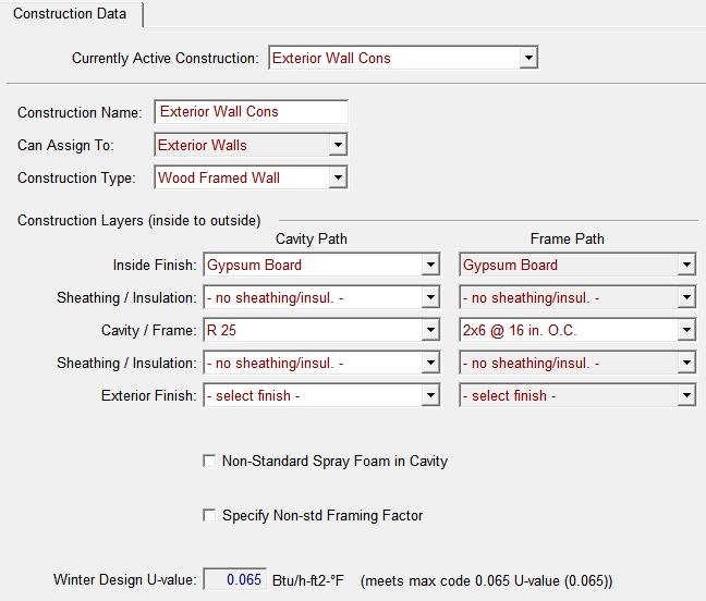
CBECC-Res Software Wall Assembly Construction showing U-0.065 Assembly
The assembly does meet the minimum mandatory wall insulation U-factor requirement of 0.074, as well as the prescriptive Package A U-factor requirement of 0.065 in Climate Zones 6 and 7.
However, the assembly does not meet the prescriptive compliance Package A U-factor requirement of 0.051 in Climate Zones 1-5 and 8-16. To meet the Package A requirement for those climate zones, other wall assemblies may be used, such as those in Figure 3-30, and/or advanced wall system (AWS) techniques may be used to reduce the framing factor. Alternatively, the project could be shown to comply with Title 24 using the performance approach, which allows energy efficiency trade-offs with other building components.
Example 3-29
Question:
A new single-family house will have six inches of framed walls with R-19 cavity insulation and R-5 continuous rigid insulation on the outside. Can this building comply with Title 24 using either the prescriptive or performance approach?
Answer:
If the house has wood framing, the assembly U-factor would be U-0.051 as per JA4 Table 4.3.1. This U-factor prescriptively complies with the Package A U-factor requirements in all climate zones, and the building would not need to use the performance approach. If the house has metal framing, the assembly U-factor would be U-0.084 as per JA4 Table 4.3.4. This U-factor exceeds the maximum U-factor allowed in the prescriptive Package A and exceeds the mandatory maximum (U-0.074). Thus, the building would not be able to comply even by using the performance method.
3.6.2.3 Floor/Slab
A. Floor Insulation
1. Raised-Floor
Package A prescriptive requirements call for R-19 or maximum U-factor of 0.037 insulation in raised floors in all climates.
The requirement may be satisfied by installing the specified amount of insulation in a wood-framed floor or by meeting an equivalent U-factor. U-factors for raised-floors are listed in Reference Joint Appendix JA4. Concrete floors separating multifamily habitable space from a parking garage are also considered a raised floor. For this class of construction, R-4 insulation is required for Climate Zones 12 and 15, and R-8 is required for Climate Zones 1, 2, 11, 13, 14, and 16. No insulation is required in other climate zones with a concrete raised floor.
|
Insulation R-value |
Crawlspace? |
Reference Joint Appendix JA4 Construction and Table Cell Entry |
Equivalent U-factor |
|
R-19 |
No |
4.4.2 A4 |
0.049 |
|
R-19 |
Yes |
4.4.1 A4 |
0.037 |
Construction Practice/Compliance and Enforcement
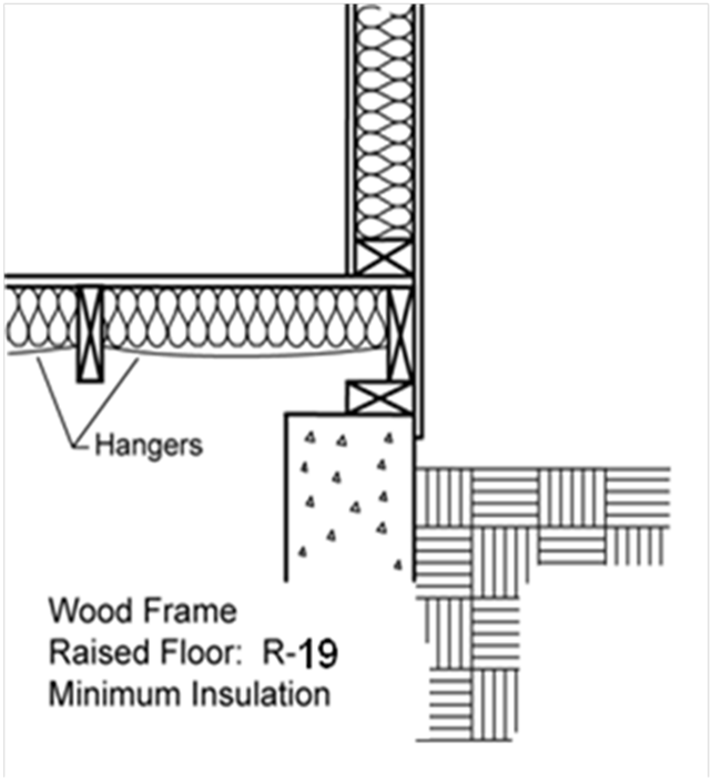
Floor insulation should be installed in direct contact with the subfloor so that there is no air space between the insulation and the floor. Support is needed to prevent the insulation from falling, sagging, or deteriorating.
Options for support include netting stapled to the underside of floor joists, insulation hangers running perpendicular to the joists, or other suitable means. Insulation hangers should be spaced at 18 inch or less before rolling out the insulation.(See Figure 3-34). Insulation hangers are heavy wires up to 48 inch long with pointed ends, which provide positive wood penetration. Netting or mesh should be nailed or stapled to the underside of the joists. Floor insulation should not cover foundation vents.
Source: California Energy Commission
2. Slab Insulation
§150.1-A of the Energy Standards, Package A, requires slab insulation only in Climate Zone 16. In this case, a minimum of R-7 must be installed. The insulation must be installed to a minimum depth of 16 in. or to the bottom of the footing, whichever is less. The depth is measured from the top of the insulation, as near the top of slab as practical, to the bottom edge of the insulation (See Figure 3-35).
Perimeter insulation is not required along the slab edge between conditioned space and the concrete slab of an attached unconditioned enclosed space such as a garage, covered porch, or covered patio. Neither would it be practical or necessary to insulate concrete steps attached to the outside slab edge.
In situations where the slab is below grade and slab edge insulation is being applied to a basement or retaining wall, the top of the slab edge insulation should be placed as close to ground level as possible and extended down at least 16 inches. In situations where the slab is above grade and slab edge insulation is being applied, the top of the slab edge insulation should be placed at the top of the slab.
Construction Practice/Compliance and Enforcement
Slab-edge insulation should be protected from physical damage and ultraviolet light exposure because deterioration from moisture, pest infestation, ultraviolet light and other factors can significantly reduce the effectiveness of the insulation. (See Figure3-31.)
When slab-edge insulation is required by the prescriptive or
performance requirements,
then minimum depth is 16 inch or to the top
of the footing, whichever is less.
Source: California Energy Commission
Example 3-30
Question:
What are the slab edge insulation requirements for a hydronic-heating system with the hot water pipes in the slab?
Answer:
The requirements for insulation of heated slabs can be found in §110.8(g) of the Energy Standards and are described in Chapter 4 of this 'manual. The material and installation specifications are as follows:
• Insulation values as shown in Table 110.8-A of the Energy Standards
• Protection from physical damage and ultraviolet light deterioration
• Water absorption rate no greater than 0.3 percent (ASTM-C272)
• Water vapor permeance no greater than 2.0 perm/inch (ASTM-E96)
Some residential designs may not wish to use or do not meet the requirements for prescriptive options A, B, and C described above in Section 3.6.2. The performance approach offers increased flexibility as well as compliance credits for certain assemblies, usually requiring HERS verification. The designs described below are examples of residential envelope strategies that can be implemented under the performance approach. The proposed design used under the performance approach is compared to the standard design, which is determined by the prescriptive requirements.
3.6.3.1 Roof Assembly
The construction techniques described below are assemblies that can be used in residential construction to help meet or perform better than minimum prescriptive requirements when using the performance compliance approach. This section describes typical constructions for unvented attics, attic ventilation, insulated tiles, and raised heel trusses (also called “energy trusses”).
A. Unvented Attics
Attic ventilation is the traditional way of controlling temperature and moisture in an attic. In an unvented attic assembly, insulation is applied directly at the roofline of the building, either above or below the structural roof rafter. The roof system becomes part of the insulated building enclosure. For this case, the thermal boundary of the building results in an unvented attic space between the ceiling gypboard and the insulated roof above (See Figure 3-36).
The provisions of CBC, Title 24, Part 2, Vol. 2.5, Section R806.4 describes conditions for insulation placed at the roof of the building as opposed to on top of the horizontal ceiling. Unvented attic assemblies are allowed provided that:
1. Air-impermeable insulation is used below and in direct contact with the underside of the roof sheathing.
2. Air-permeable insulation is used below and in direct contact with the underside of the roof sheathing and rigid board or sheet insulation of at least R-4 is used above the roof sheathing.
3. Air-impermeable insulation is used below and in direct contact with the underside of the roof sheathing, and an additional layer of air-permeable insulation is installed directly under the air-impermeable insulation.
Check with the local building jurisdiction to determine its specific requirements for unvented attic conditions.
Combining this strategy with the additional design improvement of low air leakage for the rest of the building would achieve energy savings and compliance energy credit. Furthermore, this design eliminates the need to seal or limit penetrations at the ceiling level, such as recessed cans, because the air and thermal boundary is now located at the roof deck.
Figure 3-36: Unvented
Attic Assembly With Insulation at
the Ceiling and Between the Roof
Rafters

Source: California Energy Commission
A. Below-Deck Netted Insulation
Alternative types of insulation can provide high R-value insulation below the roof deck in an unvented attic. One approach is a boxed netted system that is suspended from the top member of the truss, or top chord, to provide a fill depth that completely encloses the top chord, creating a uniform insulation layer of loose-fill fiberglass across the entire underside of the roof deck. This method can be done with common loose-fill insulation tools and equipment. See Figure 3-37A for details of this type of below-deck netted insulation. Draped netted insulation, another approach to below deck insulation, results in a non-uniform insulation layer, created by leaving the truss chords exposed and leading to increased thermal bridging (see Figure 3-37B).
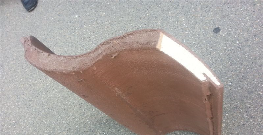
B. Insulated Roof Tiles
Insulating roof tile (IRT) is another option for improving the thermal performance of the roof assembly and lowering attic temperatures. IRT combines concrete/clay tiles with insulation as a packaged product. Most of the increase in R-value is due to the integration of insulation into the roofing product itself; however, additional thermal performance can be gained by combining IRT with rigid foam insulation inserts (Figure 3-39). These tiles are lighter than typical roof tiles and have better thermal performance than traditional tiles due to the insulation core.
Furthermore, IRT can reduce radiant losses and maintain warmer roof deck temperatures, thereby reducing the potential for condensation. Using one of the options below provides additional R-value when conventional (ceiling) insulation is also installed. All four configurations (A-D) can be installed without any significant changes to conventional roof or attic design (such as changes to fascia dimensions, and so forth), and IRT can be used in both vented and unvented attic configurations.
Source: Green Hybrid Roofing
(A)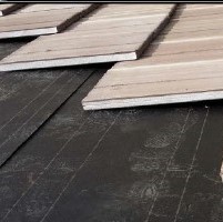 (B)
(B)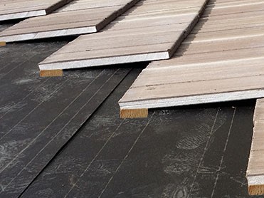
(C)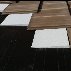 (D)
(D)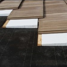
Source: Green Hybrid Roofing
Some IRTs are ASTM rated for Class A fire rating (ASTM E108) and have CRRC certification for cool roof tiles in several colors. Depending on the configuration selected from the four options (A-D) in Figure 3-39, a U-factor between 0.18 and 0.10 can be achieved, with option D performing the best. It is best practice to check with manufacturers about the ratings and certifications for each tile. Product manufacturers cite several advantages of the product due to its lightweight construction and increased insulation properties – ease of installation, ability to install similar to traditional roof tiles but at a much faster pace, less weight on the roof structure, increased thermal resistance, and improved thermal performance.
C. Raised Heel or Extension Truss (Energy Truss)
The use of an energy truss, usually referred to as a raised heel or extension truss, allows full depth, uncompressed insulation at the ceiling to continue to the ceiling edge where the roof and ceiling meet. For this strategy, the roof truss is assembled with an additional vertical wood framed section at the point where the top and bottom truss chords meet. The vertical section raises the top chord and provides increased space that can be filled with insulation. See Figure 3-40 for details of a raised heel truss. Benefits of this strategy include:
•Realizing the full benefit of ceiling insulation.
•Providing more space for air handler and duct systems if located in the attic.
The 2016 CBECC-Res compliance software allows for the modeling of raised heel trusses and provides credit for the additional insulation at the edges.
Other methods to achieve the similar outcome include framing with a rafter on raised top plate or using spray foam or rigid foam at the edge.


Source: Georgia Department of Community Affairs
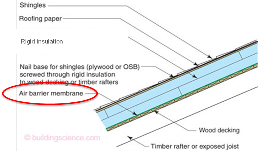
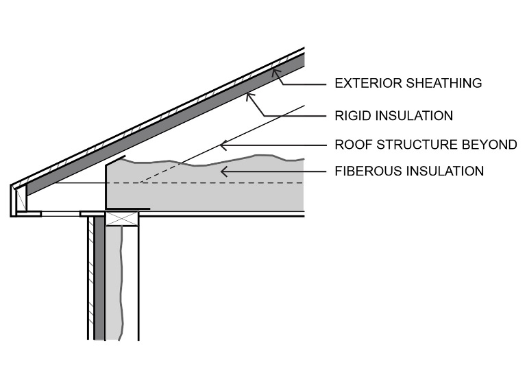
D. Nail Base Insulation Panel
The nail base insulation panel is an above-roof rafter insulation strategy that consists of exterior-facing OSB or other structural sheathing laminated to continuous rigid insulation, which is fastened directly to roof framing. (See Figure 3-40A). This saves the time and expense of installing a structural sheathing layer above and below the rigid insulation. The nail base insulation panel creates a nailing surface for the attachment of roof cladding. Suitable for both vented and unvented attic assemblies, the exposed underside of the rigid insulation has a facer that provides a radiant barrier as well as ignition/thermal barrier protection as required by code.
3.6.3.2 Wall Assembly
See Energy Commission videos
A. Advanced Wall System (AWS)
Advanced wall systems (AWS), also known as optimum value engineering (OVE), refers to a set of framing techniques and practices that minimize the amount of wood and labor necessary to build a structurally sound, safe, durable, and energy-efficient building. AWS improves energy and resource efficiency while reducing first costs.
Reducing the amount of wood in wood-framed exterior walls improves energy efficiency, allowing more insulation to be installed, and has greater resource efficiency for the materials being used. In addition, using fewer framing studs reduces the effects of “thermal bridging” and increases the amount of insulation in the wall, resulting in a more energy-efficient building envelope. The framing factor assumed for calculating the energy performance of a wood framed 2x4 wall at 16” oc is 25 percent. When AWS is used, the framing factor is reduced to 17 percent, reflecting the improved energy performance of the wall system.
While AWS represents a range of practices, it must be adequately inspected to ensure framing contractors have adhered to all best practice construction throughout the exterior envelope. Examples of construction practices for AWS that can be used as a general guide for enforcement are provided below:
1. Use a minimum 2x6 at 24” on-center wall framing.
2. Use precise engineering of headers on load-bearing walls.
3. Install 2x4, 2x6, or I-joist headers on exterior nonload-bearing walls.
4. Eliminate cripple studs at window and door openings less than 4 feet wide.
5. Align window/door openings with standard stud spacing.
6. The king stud, on at least one side of the window/door opening, must take the place of an on-layout AWS stud.
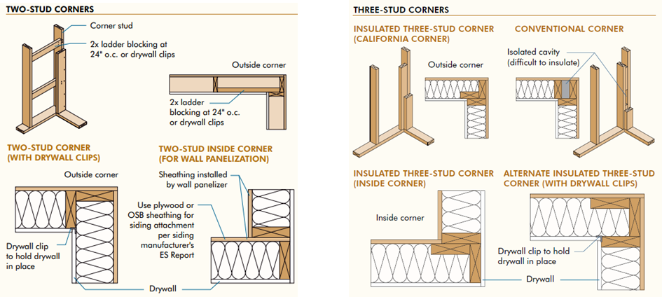
7. Use an insulated corner, either a two-stud corner or a California (3-stud) corners, as in the examples provided in Figure 3-41.
8. Nailing for interior gypsum board can be accomplished with drywall clips, 1x nailer strip, recycled plastic nailing strip. Drywall clips reduce the potential for drywall cracking.
9. Use ladder block where interior partitions intersect exterior walls, instead of 3-stud channels.
10. Eliminate unnecessary double-floor joists underneath nonbearing walls.
11. Use metal let-in T-bracing or other methods on non-shear walls to allow full insulation.
12. Include detailed framing plans and elevations on the construction permit plan set.
13. Optimize house design for efficient material use (for example, reducing header spans, designing exterior surfaces in two-foot modules, designing clear spans to eliminate interior bearing walls).
14. Build with “insulated headers” (a “sandwich” of two solid or engineered lumber components with a layer of foam insulation in the middle or on one or both sides of the header). An example of a single-ply insulated header is provided in Figure 3-42. Insulated headers may also earn QII compliance credits by installing R-2 insulation in one of three ways:
a. Two-member header with insulation in between. The header and insulation must fill the wall cavity. There are prefabricated products available that meet this assembly. Example: a 2x4 wall with two 2x nominal headers, or a 2x6 wall with a 4x nominal header and a 2x nominal header. Insulation is required to fill the wall cavity and must be installed between the headers.
b. Single-member header, less than the wall width, with insulation on the interior face. The header and insulation must fill the wall cavity. Example: a 2x4 wall with a 3-1/8-inch-wide header, or 2x6 wall with a 4x nominal header. Insulation is required to fill the wall cavity and must be installed to the interior face of the wall.
c. Single-member header, same width as wall. The header must fill the wall cavity. Example: a 2x4 wall with a 4x nominal header or a 2x6 wall with a 6x nominal header. No additional insulation is required because the header fills the cavity.
Wood structural panel box headers may also be used as load-bearing headers in exterior wall construction, when built in accordance with 2015 CRC Figure R602.7.3 and Table R602.7.3.
15. Use engineered lumber. Examples include: “I”-joists, open web floor trusses, 2x “raised heel” roof trusses, glulam beams, laminated veneer lumber (LVL), laminated strand lumber (LSL), parallel strand lumber (PSL), oriented strand board (OSB).
16. Eliminate trimmers at window and door opening headers less than 4 ft wide, only when rated hangers are used and noted on the plans.
17. Use 2x4 or 2x3 interior nonload-bearing walls.
18. Integrate framing design with HVAC system.
19. Use “inset” shear wall panels.
Source: APA Advanced Framing Guide
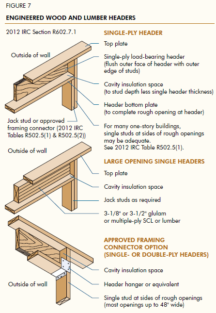
Figure 3-43 below is a description of one AWS and the assembly characteristics that are used in the prescriptive and performance compliance approaches. This assembly meets a U-factor of 0.051 with an exterior insulation of R-4, due to 24” stud spacing and R-7 header assemblies. The building official must ensure during planning, to check the accuracy of the parallel heat flow calculation and, during framing, inspect that all elements of AWS have been met.
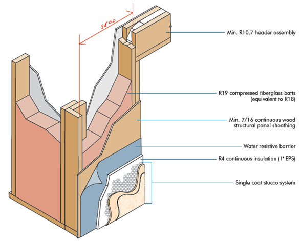
Source: APA, The Engineered Wood Association
|
Layer |
Assembly Type: Wall 2x6 @ 24” oc AWS |
R-Value | ||
|
Framing Material: Wood | ||||
|
Assembly Components |
Cavity (Rc) |
Frame (Rf) |
Header (Rh) | |
|
0 |
Frame Factor |
78% |
18% |
4% |
|
1 |
Outside air film |
0.17 |
0.17 |
0.17 |
|
2 |
Building paper |
0.06 |
0.06 |
0.06 |
|
3 |
3/8 inch single coat stucco |
0.08 |
0.08 |
0.08 |
|
4 |
R4 continuous insulation (1” EPS) |
4 |
4 |
4 |
|
5 |
7/16 inch continuous oriented strand board sheathing (OSB) |
0.44 |
0.44 |
0.44 |
|
6 |
R-18 compressed fiberglass batts |
18.0 |
-- |
-- |
|
7 |
Header assembly – 3.5” wood |
|
|
3.46 |
|
8 |
Header assembly – 1 inch of R4 foam |
|
|
4 |
|
9 |
2x6 douglass fir framing @ R-1.086/inch |
-- |
5.973 |
-- |
|
10 |
½ inch gypboard |
0.45 |
0.45 |
0.45 |
|
11 |
Inside air film |
0.68 |
0.68 |
0.68 |
|
|
Subtotal R-Values |
23.875 |
11.848 |
13.335 |
|
|
U-Factors (Frame % x 1/R) |
0.0327 |
0.0152 |
0.0030 |
Assumptions: Values in Table 3-7 were calculated using the parallel heat flow calculation method, documented in the 2009 ASHRAE Handbook of Fundamentals and outlined in Joint Appendices JA4.1.2 and JA4.6. The construction assembly in Table 4.6.1 in JA4.6 assumes an exterior air film of R-0.17, a 3/8-inch layer of stucco of R-0.08 (SC01), building paper of R-0.06 (BP01), sheathing or continuous insulation layer, if present, the cavity insulation/framing layer, ½-inch gypsum board of R-0.45 (GP01), and an interior air film 0.68. The framing factor is assumed to be 25 percent for 16-inch stud spacing, 22 percent for 24-inch spacing, and 17 percent for advanced wall system (AWS). Actual cavity depth is 3.5 inch for 2x4, 5.5 inch for 2x6.
B. Double and Staggered Wall Assemblies
Double-wall and staggered-wall systems were developed to better accommodate electrical and plumbing systems, allow higher levels of insulation, and provide greater sound attenuation. The advantages of these types of wall systems are:
1. Smaller dimensional lumber can be used.
2. It is easier to install installation properly.
3. It eliminates thermal bridging through the framing.
4. It reduces sound transmission through the wall.
With double walls, insulation may be on one side of the wall or on both (higher R-values). It is not uncommon to find double walls with insulation installed within the outside wall cavities, leaving the inside wall sections open for wiring and plumbing. (See Figure 3-44.)
With staggered walls, thermal batt insulation may be installed horizontally or vertically, butting the sides of the insulation until the cavity across the entire wall section is completely filled.
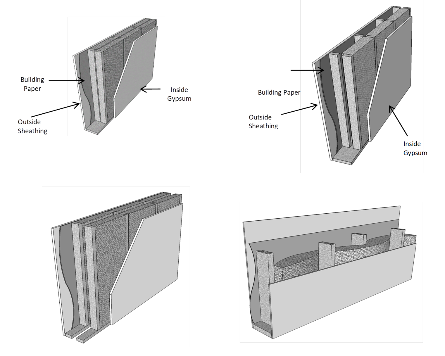
Source: California Energy Commission
C. Metal Framing
A change from wood framing to metal framing can significantly affect compliance. Metal-framed assemblies are often chosen where greater structural integrity is necessary, or in climate conditions where greater durability is desired from the effects of excessive moisture exposure. Metal-framed wall construction generally requires a continuous layer of rigid insulation to meet the mandatory minimum wall insulation levels and/or the prescriptive requirements since metal is more conductive than wood. In JA4, Tables 4.2.4 and 4.2.5 have U-factors for metal-framed ceiling/roof constructions. Table 4.3.4 has U-factors for metal-framed walls. Tables 4.4.4 and 4.4.5 have U-factors for metal-framed floors.
To comply prescriptively, a non-wood-framed assembly, such as a metal-framed assembly, must have an assembly U-factor that is equal to or less than the U-factor of the wood-framed assembly for that climate zone. Compliance credit is available through the performance approach for metal-framed assemblies that exceed the prescriptive requirements of the equivalent wood-framed assemblies.
D. High-Performance Structural Foam Wall System
The high-performance structural foam wall assembly is an Advanced Assembly System that consists of ccSPF placed in the cavity bonded to wood framing and continuous rigid board insulation on the exterior of the frame. The bond that occurs between the ccSPF, the framing, and the continuous rigid insulation can provide code-compliant wind and seismic structural load resistance without the use of OSB sheathing (See Figure 3-44A).
use ccSPF to insulate, air seal, and structurally bond together exterior foam sheathing with wall framing to allow builders to construct 2x4 at 24” O.C. while improving structural and thermal performance.
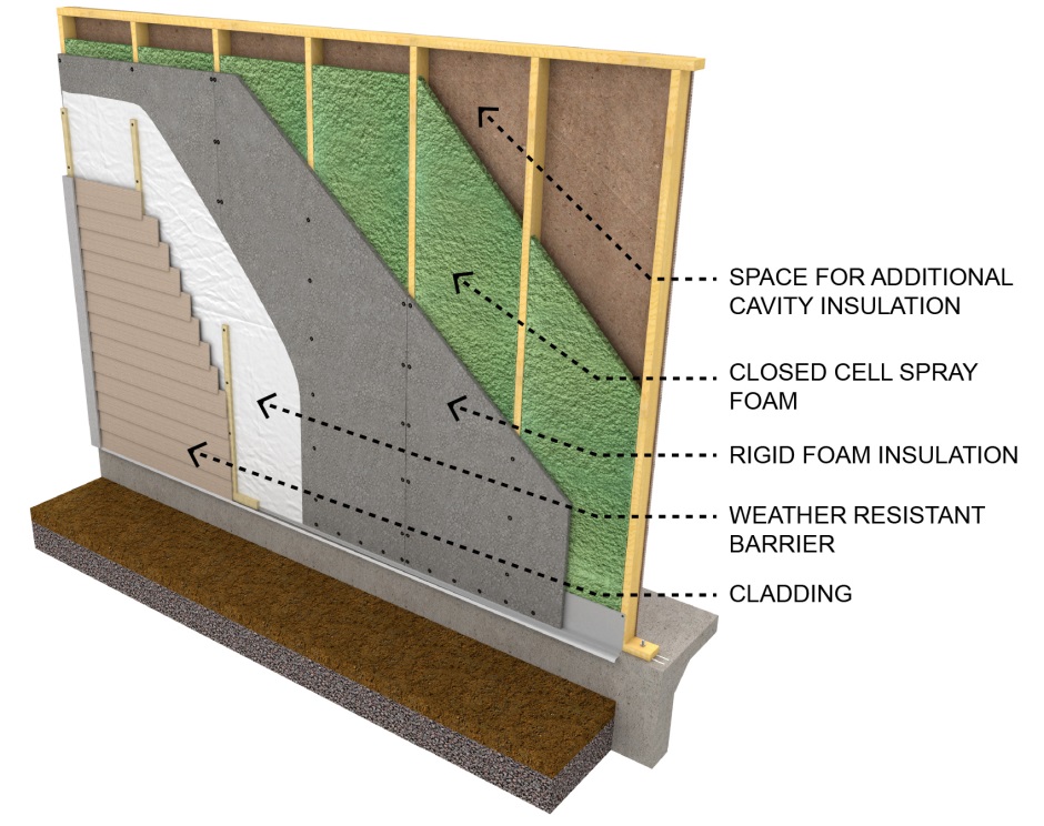
Source: BASF Corporation
A builder can configure the thicknesses of the cavity ccSPF, rigid insulation, and alternative cavity insulation to attain U-factors of 0.050 or better in 2x4 at 24” OC assembly. The structural foam wall assembly can be combined with advanced framing or OVE techniques to increase energy and resource efficiency while reducing both material cost and labor.
3.6.3.3 Floor Assembly
A. Controlled Ventilation Crawl Space (CVC)
CVC Eligibility Criteria in 2016 RA4.5.1
Buildings that have crawl space foundations must meet mandatory and prescriptive requirements for insulation of a raised floor separating the unconditioned crawl space from conditioned space above (§150.0(d) and §150.1(c)1C). An alternative to underfloor insulation is insulating the stem wall of the foundation crawl space. Insulating the crawl space foundation can improve the thermal efficiency of the floor system by:
1. Reducing heat transfer into the unconditioned crawl space.
2. Reducing moisture buildup in the crawl space.
3. Minimizing insulation exposure to adverse weather prior to enclosure of the building shell.
An energy credit can be taken in compliance software for controlled ventilation crawl space (CVC). This credit requires insulating the foundation stem wall, using automatically controlled crawl space vents, and vapor retarder covering the entire ground soil area for moisture control on the crawl space floor.

Source:
California Energy Commission
All building designs should ensure that proper site engineering and drainage away from the building is maintained. This includes landscaping techniques that emphasize sound water management strategies:
1. Drainage: Crawl space buildings in particular are susceptible to moisture ponding when good drainage and/or moisture removal designs are not employed.
2. Ground water and soils: Local groundwater tables at maximum winter recharge elevation should be below the lowest excavated elevation of the site foundation. Sites that are well-drained and that do not have surface water problems are generally good candidates for this stem wall insulation strategy. However, allowance for this alternative insulating technique is entirely at the enforcement agency’s discretion. The building permit applicant should be prepared to provide supporting information that site drainage strategies (for example, perimeter drainage techniques) will prevent potential moisture concerns.
The following eligibility criteria in RA4.5.1 are required in order to use the CVC energy credit:
1. Ventilation: All crawl space vents must have automatic vent dampers. Automatic vent dampers must be shown on the building plans and installed. Dampers shall be temperature actuated to be fully closed at about 40°F and fully open at about 70°F. Cross-ventilation consisting of the required vent area shall be distributed between opposing foundation walls.
2. Insulation: The R-value of insulation placed on the foundation stem wall shall be equal to or greater than the wall insulation above the raised floor. Stem wall insulation shall run vertically along the stem wall and horizontally across the crawl space floor for a distance of 2 ft (24 inches).
3. Direct Earth Contact: Foam plastic insulation used for crawl space insulation having direct earth contact shall be a closed–cell, water-resistant material and meet the slab edge insulation requirements for water absorption and water vapor transmission rate specified in the mandatory requirements (§110.8(g)1).
A Class I or Class II vapor retarder rated as 1.0 perm or less must be placed over the earthen floor of the crawl space to reduce moisture entry and protect insulation from condensation in accordance with RA4.5.1. This requires essentially a polyethylene-type ground cover having a minimum 6 mil thickness (0.006 inch) or approved equal. The vapor retarder must be overlapped a minimum of 6 inches at joints and shall extend over the top of footings and piers. All overlapping of joints shall be sealed with tape, caulk, or mastic.
•Penetrations, tears, and holes in the vapor barrier shall be sealed with tape, caulk, or mastic.
•Edges of the vapor retarder shall be turned up a minimum of 4 inches at the stem wall and securely fastened and before insulation is installed.
•In sloping crawl space ground soil areas, the vapor retarder shall be securely held in place, such as spiked with 5-inch gutter nails, then have proper sealing of penetration holes.
•The vapor retarder shall be shown on the plans.
3.6.3.4 Quality Insulation Installation (QII)
Energy Commission videos RA3.5
All insulation shall be installed properly throughout the building. When compliance credit is taken for QII, a third-party HERS Rater is required to verify the integrity of the installed insulation. The installer shall provide evidence with compliance documentation that all insulation specified is installed to meet specified R-values and assembly U-factors.
Many residential insulation installations have flaws that degrade thermal performance. Four problems are generally responsible for this degradation:
1. There is an inadequate air barrier in the building envelope, or holes and gaps within the air barrier system inhibit the ability to limit air leakage.
2. Insulation is not in contact with the air barrier creating air spaces that short-circuits the thermal barrier of the insulation when the air barrier is not limiting air leakage properly.
3. The insulation has voids or gaps resulting in portions of the construction assembly that are not insulated and, therefore, has less thermal resistance than other portions of the assembly.
4. The insulation is compressed, creating a gap near the air barrier and/or reducing the thickness of the insulation.
Figure 3-46 – Examples of Poor Quality Insulation Installation
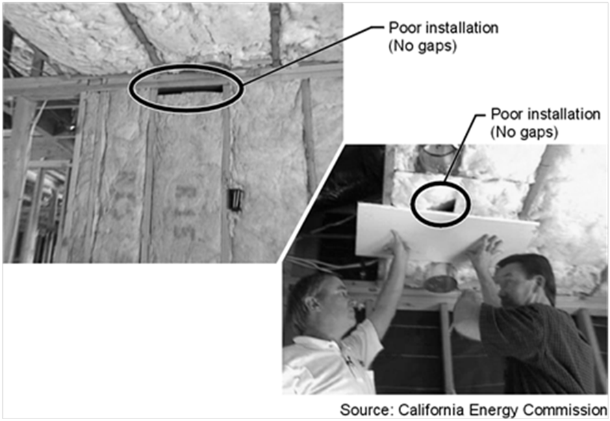
An energy credit for correctly installing an air barrier and insulation to eliminate or reduce common problems associated with poor installation is provided in the RA3.5. This compliance credit applies to framed and nonframed assemblies. Residential construction may incorporate multiple frame types, for example, using a combination of nonframed walls with a framed roof/ceiling. Likewise, multiple insulation materials are often used. Framed assemblies include wood and steel construction insulated with batts of mineral fiber, mineral and natural wool, and cellulose; loose-fill insulation of mineral fiber, mineral and natural wool, cellulose, and SPF; and rigid board insulation used on the exterior or interior of framed or nonframed assemblies. Nonframed assemblies include structural insulated panels, insulated concrete forms, and mass walls of masonry, concrete and concrete sandwich panels, log walls, and straw bale.
This compliance credit can only be taken for the whole building—roof/ceilings, walls and floors − and requires field verification by a third-party HERS Rater. Further explanation is provided below:
1. Compliance credit is not allowed for walls alone, or credit is allowed for roofs/ceilings but not walls also.
2. Compliance credit is allowed for a building built on a slab floor, where the slab has no requirement for insulation. However, if insulation is installed (that is, slab edge insulation for radiant floor heating), then the integrity of the slab edge insulation must also be field-verified in 'addition to the air barrier and insulation system for walls and the roof/ceiling.
3. Combinations of insulation types (hybrid systems) are allowed.
4. An air barrier shall be installed for the entire envelope.
5. Compliance credit is allowed for additions to existing buildings where energy compliance has been demonstrated for the “addition alone” (§150.2(a).
6. Compliance credit is not allowed for additions to existing buildings where the “existing plus alteration plus addition” approach is used (§150.2(a)2B).
7. Compliance credit is not allowed when using the PV trade-off package.
Approved computer compliance modeling software automatically reduces the effectiveness of insulation for compliance. This reduction is accounted for in developing the Energy Standards and prescribing the required prescriptive measures for each climate zone to establish the standard design energy budget in performance compliance calculations. The effect of a poorly installed air barrier system and envelope insulation results in higher wall heat loss and heat gain than standard R-value and U-factor calculations would indicate. Similar increases in heat loss and heat gain are experienced for roof/ceilings where construction and installation flaws are present.
To take advantage of the QII energy credit, two primary installation criteria must be adhered to and they both must be field verified by a HERS Rater.
A. Structural Bracing, Tie-Downs, Steel Structural Framing
When metal bracing, tie-downs or steel structural framing is used to connect to wood framing for structural or seismic purposes the QII energy credit still can be taken if:
1. Metal bracing, tie-downs or steel structural framing is identified on the structural plans.
2. Insulation is installed in a manner that restricts the thermal bridging through the structural framing assembly.
3. Insulation fills the entire cavity and/or adheres to all sides and ends of structural assembly that separates conditioned from unconditioned space.
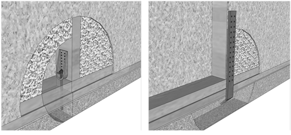
Source: California Energy Commission
B. Air Barrier
An air barrier shall be installed enclosing the entire building. When this credit is shown to be taken on compliance documentation a third-party HERS Rater is required to verify the integrity of the air barrier system. The air barrier must be installed in a continuous manner across all components of framed and nonframed envelope assemblies. The installer shall provide evidence with compliance documentation that the air barrier system meets one or more of the air barrier specifications shown in Table 3-8 below. More detailed explanation is provided in RA3.5. Documentation for the air barrier includes product data sheets and manufacturer specifications and installation guidelines. The third-party HERS Rater shall verify that the air barrier has been installed properly and is integral with the insulation being used throughout the building.
|
Continuous Air Barrier |
A combination of interconnected materials and assemblies are joined and sealed together to provide a continuous barrier to air leakage through the building envelope separating conditioned from unconditioned space, or adjoining conditioned spaces of different occupancies or uses. An air barrier is required in all thermal envelope assemblies to limit air movement between unconditioned/outside spaces and conditioned/inside spaces and must meet one of the following: 1. Using materials that have an air permeance not exceeding 0.004cfm/ft2 under a pressure differential of 0.3in. w.g. (1.57psf) (0.02 L/s.m2 at 75 pa) when tested in accordance with ASTM E2178. 2. Using assemblies of materials and components that have an average air leakage not to exceed 0.04 cfm/ft2 under a pressure differential of 0.3 in. w.g (1.57psf) (0.2 L/s.m2 at 75 pa) when tested in accordance with ASTM E2357, ASTM E1677, ASTM E1680 or ASTM E283. 3. Testing the completed building and demonstrating that the air leakage rate of the building envelope does not exceed 0.40 cfm/ft2 at a pressure differential of 0.3 in w.g. (1.57 psf) (2.0 L/s.m2 at 75 pa) in accordance with ASTM E779 or an equivalent approved method. Materials and assemblies of materials that can demonstrate compliance with the air barrier testing requirements must be installed according to the manufacturer's instructions, and a HERS Rater shall verify the integrity of the installation. Below are example materials meeting the air permeance testing performance levels of 1 above. Manufacturers of these and other product types must provide a specification or product data sheet showing compliance to the ASTM testing requirements to be considered as an air barrier. Plywood – minimum 3/8 inch Oriented strand board – minimum. 3/8 inches Extruded polystyrene insulation board – minimum. ½ inch Foil-back polyisocyanurate insulation board – minimum. ½ inch Foil backed urethane foam insulation (1 inch) -- Closed-cell spray polyurethane foam (ccSPF) with a minimum density of 2.0 pcf and a minimum thickness of 2.0 inches. Alternatively, ccSPF insulation shall be installed at a thickness that meets an air permeance no greater than 0.02 L/s-m2 at 75 Pa pressure differential when tested in accordance to ASTM E2178 or ASTM E283. -- Open cell spray polyurethane (ocSPF) foam with a minimum density of 0.4 to1.5 pcf and a minimum thickness of 5½ inches. Alternatively, ocSPF insulation shall be installed at a thickness that meets an air permeance no greater than 0.02 L/s-m2 at 75 Pa pressure differential when tested in accordance to ASTM E2178 or ASTM E283. Exterior or interior gypsum board - minimum 1/2 inch Cement board - minimum 1/2 inch Built-up roofing membrane Modified bituminous roof membrane Particleboard-minimum 1/2 inch Fully adhered single-ply roof membrane Portland cement/sand parge ,or gypsum plaster minimum 5/8 inch Cast-in-place and precast concrete. Fully grouted uninsulated and insulated concrete block masonry Sheet steel or aluminum |
C. Reduced Building Air Leakage
An energy credit is allowed through the performance approach when the rate of envelope air leakage of the building is less than the air leakage rate assumed for the standard design building. A third-party HERS Rater shall verify the air leakage rate shown on compliance documentation through diagnostic testing of the air leakage of the building.
The air leakage testing (blower door) involves closing all the windows and doors; pressurizing the house with a special fan, usually positioned in a doorway (see Figure 3-48); and measuring the leakage rate, measured in cubic feet per minute at a 50 Pa pressure difference (CFM50). This measurement procedure is described in the RA3.8. It is derived from the Residential Energy Services Network's (RESNET) Mortgage Industry National Home Energy Rating Standards, Standard 800, which is based on ASTM E779 air-tightness measurement protocols. This procedure requires the use of software consistent with ASTM E779. This test method is intended to produce a measure of the air tightness of a building envelope for determining the energy credit allowance for reduced building air leakage. Further explanations are described below:
1. This procedure shall be used only to verify the building air leakage rate before the building construction permit is finalized when an energy credit for reduced air leakage is being claimed on compliance documentation.
2. The Home Energy Rating System (HERS) Rater shall measure the building air leakage rate to ensure measured air leakage is less than or equal to the building air leakage rate stated on the certificate of compliance and all other required compliance documentation. HERS-verified building air leakage shall be documented on compliance forms.
3. This is a whole-building credit; therefore, no credit is allowed for the installation of individual envelope measures that may help in reducing the air leakage rate of the building’s, such as for an exterior air retarding wrap, or for an air barrier material or assembly meeting the requirements describe in Table 3-8 above.

D. Structural Insulated Panels (SIPS)
Structural insulated panels (SIPS) are a nonframed advanced construction system that consists of rigid foam insulation sandwiched between two sheets of board. The board can be sheet metal, plywood, cement, or oriented strand board (OSB), and the foam can be expanded polystyrene foam (EPS), extruded polystyrene foam (XPS) or polyurethane, or polyisocyanurate (polyiso) foam. SIPs combine several components of conventional building, such as studs and joists, insulation, vapor barrier, and air barrier. They can be used for many different applications, such as exterior walls, roofs, floors, and foundation systems. Little or no structural framing penetrates the insulation layer. Panels are typically manufactured at a factory and shipped to the job site in assemblies that can be as large as 8 ft by 24 ft.
In the field, the SIPS panels are joined in one of three ways: (1) single or double 2x splines, (2) I-joists, or (3) with OSB splines. The choice of these options affects thermal performance and structural capacity. The 2x and I-joist spline types fit in a recess of the foam core, between the two layers of plywood or OSB. JA4, Table 4.2.3 contains U-factors for roof/ceiling assemblies, JA4 Table 4.3.2 has U-factors for SIPS wall assemblies and JA4 Table 4.4.3 has U-factors for SIPS floor constructions. U-factors used for compliance must be taken from these tables or by using approved performance compliance software.

E. Insulating Concrete Forms (ICF)
Insulating concrete forms (ICFs) is a system of formwork for concrete that stays in place as permanent building insulation is used for cast-in-place, reinforced above- and below-grade concrete walls, floors, and roofs. ICFs are interlocking modular units that can be dry-stacked (without mortar) and filled with concrete as a single concrete masonry unit (CMU). ICFs lock together externally and have internal metal or plastic ties to hold the outer layer(s) of insulation to create a concrete form for the structural walls, roof/ceilings, or floors of a building. ICFs are manufactured from several materials, including expanded and extruded polystyrene foam, polyurethane foam, cement-bonded wood fiber, and cement-bonded polystyrene beads.
Three factors contribute to the energy efficiency of buildings using an ICF wall:
1. Continuous rigid insulation on both sides of a high-mass core,
2. Elimination of thermal bridging from wood framing components, and
3. A high degree of air-tightness inherent to this method of construction.
Climate zones with large daily temperature fluctuations have the greatest potential to benefit from the time lag and temperature dampening effects of these high-mass envelope systems. However, this combination of mass and insulation is beneficial in almost all climates, with the possible exception of mild coastal climate zones.
There are three basic types of ICFs: flat wall, waffle-grid and screen-grid. A flat wall ICF results in a wall with a consistent and continuous thickness of concrete. A waffle-grid ICF creates a concrete waffle pattern, an uninterrupted grid, with some concrete sections thicker than others. A screen-grid ICF consists of a discrete post-and-beam structure with the concrete completely encapsulated by the foam insulation, except at the intersection of posts and beams. The insulating panels for all three ICF types are most commonly made from expanded polystyrene (EPS) and extruded polystyrene (XPS) rigid insulation boards. Insulating panels are also made from polyurethane, composites of cement and EPS, and composites of cement and shredded wood fiber, although these tend to be proprietary materials developed by the ICF manufacturer.
Plastic or metal cross-ties, consisting of two flanges and a web, separate the insulating panels and provide structural integrity during the pouring of concrete, resulting in a uniform wall thickness. A variety of wall thicknesses can be obtained by changing the length of the web. The area of attachment of the cross-ties to the insulating form provides a secure connection surface located at standard spacings for mechanical attachment of finished materials to the interior and exterior of the wall. ICFs can be used to construct load-bearing and nonload-bearing walls and above- and below-grade walls, and can be designed to structurally perform in any seismic zone.
The ICF system is modular and stackable with interlocking edges. The materials can be delivered as preassembled blocks or as planks that require the flanges and web to be assembled during construction. The forms vary in height from 12” - 24” and are either 4’ or 8’ long. Vertical panels come in similar modules but are stacked vertically. ICF panels are typically available with core thickness ranging from 4” to 12”.
The thermal aspects of ICFs are represented in the JA4, Table 4.3.13.